3.1 Brief Review of Computer-Aided Tomography
Computer-Aided Tomography, or CAT (as in CAT scan) is a technique for remote 2-D and 3-D imaging. By moving a sensor around a target, one can collect sufficient 1-dimensional data to reconstruct the original multidimensional image. This process utilizes an amazing relationship called the Projection-Slice Theorem, which states that each piece of projection data at some angle is the same as the Fourier transform of the multidimensional object at that angle. Using a range of data from a range of angles, one can, given sufficient computation resources, reconstruct the actual image by taking the inverse transform. The Projection-Slice Theorem has found a range of applications in remote sensing, the most famous of which is the 3-D imaging of humans, popularly known as the CAT scan. The focus of this project, Spotlight-Mode Synthetic Aperture Radar, uses the Projection Slice Theorem in a way quite similar to CAT scan technology, except the way radar projections are generated by the image is slightly different from the way CAT scans use X-rays.
3.1.1 Projection-Slice Theorem
Let g(x,y) represent the radar reflection of our image. The two-dimensional Fourier transform of g is dened as
![]()
Figure 3.1
And
![]()
Figure 3.2
We can model the reflection behavior of the incident radar by considering the following overhead diagram
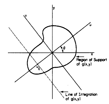
Figure 3.3
The smooth line outlines our image g(x,y), and the horizontal and vertical axes x,y are overlaid. The radar is incident upon the target along the axis of the path u at an angle theta. For a target which is far away, the radar wave front is approximately at, and so this means that a reflected beam which has traveled a certain unique distance to and from the sensor comes from a straight path across the image, perpendicular to u. This path is in the direction of v and can be represented by a line integral in the direction of v at position u0. The formula for this is given by
![]()
Figure 3.4
The 1-D Fourier transform of p(u) is given by
![]()
Figure 3.5
And then, through applying the equation for p(u) and simplifying, we are left with
![]()
Figure 3.6
This is the Projection Slice Theorem! What this states is that the Fourier transform of a projection taken at an angle theta is equal to the 2-D Fourier transform of the image at that same angle theta. To reconstruct the original image, one must merely take the inverse Fourier transform in two dimensions of a set of data P(U). This is not as easy as it sounds for reasons discussed later. Notice how the Fourier transform of the image G does not have the usual form, G(X,Y). It is instead expressed in polar form, and the variable theta lets us know that we have only a slice of the transform for each P(U).