Called as Nodular Iron.
In this alloy, as the Graphite nodules are separate & unconnected, the metallic
Matrix dictates the properties that are achievable. This material has good
Machinability & some amount of Vibration Dampening properties because
of presence of Graphite
It’s properties have been discussed ( in Ferrous Foundry Practice )
Compacted Graphitic iron. In Grey Iron ,the flakes of Graphite have Sharp
Edges & as there is absolutely NO connection between Metal & Graphite, it is
As good as hole being present (INCOHERENCY). These sharp edges act as
stress raisers leading to premature Fracture propagation.
In case C,G iron, sharp edges are ABSENT, as a result C.G. Irons do show
some amount of ductility.
An undertreated S.G. Iron or faded S.G .Iron would behave like C.G. Iron.
CARBON EQUIVALENT ( C.E.) = % C + 0.31 x % Si + 0.33 x %P +
0.05 x % Ni + 0.075 x % Cu—0.06 x % Cr –0.03 x % Mn --0.1 x % V
--0.11 x % Mo
C.E. value tells you as to how far are you from 4.3.
There is another problem which we need to understand.
Let us take an alloy with 1.2 % C & 12 % Cr.
C.E. = 1.2 % ( C)—0.06 x 12% Cr
= 1.2 –0.72 = 0.48. THIS MUST BE DEFENITELY STEEL.
BUT IT IS A CAST IRON.
THIS IS BECAUSE Cr IS A FERRITE STABILIZER. So IT SHRINKS
AUSTENITIC AREA. So Our idea of up to 2.0 C.E is STEEL does not hold
good any more.
Cast iron starts at a C level much lesser than 2.0.( if Ferrite stabilizers are
present. Except Ni, Mn, N all alloying elements are Ferrite stabilizers )
This is not a hearsay, but my practical Experience.
In Grey cast iron, the type of Graphite present decides the properties that can be
103
Achieved.
The Graphite, can be in several forms.
1) Type “ A “ Graphite flake ( Normal & desirable )
2)Type “ B “ Graphite flake ( Rosette )
3) Type “ C “ Graphite flake—which occurs in Hypereutectic Grey Irons.
4) Type “ D “ Graphite flake—Under cooled
5) Type “ E “ Graphite flake – inter dendritic
In a Good Grey Iron casting, only “ A “ type Graphite is preferred .It gives the
Best of Properties. Type A Graphite is achieved by Good Inoculation.
Alloy Cast Irons:
Austenitic Irons:
1) Corrosion Resistance--- Ni- Resist type.
2) Low Expansion ---Minover type.
3) Non Magnetic--------- No-mag type.
4) High temperature Resistance—Nicrosilal type.
1) Corrosion Resistance type of cast iron has a composition of :
% C 2.2 to 3.0.
% Si 1.0 to 4.0.
% Mn 0.4 to 1.5
% Ni 13.00 to 32.00
% Cr 1.0 to 4.5.
2) Low Expansion Type:
All though normal Austenitic Steels & Cast Irons have a Coefficient of
Thermal Expansion of 18 x 10 -6 per degree, a group of High Nickel
Irons with 35 to 36 % Ni have a Thermal Expansion varying from
4 to 8 x 10 -6 per degree.
3) Non magnetic cast irons :
% C 3.5
% Si 2.2
% Mn 5.0
% Ni 10 to 11
These alloys have a Ms temperature of --166 degrees.
4)High Temperature Resistance cast irons have a composition of
% C 1.6 to 2.2
%Si 4.0 to 4.5
%Mn 0.6 to 1.2
% Ni 18 to 22
% Cr 2.0 to 4.0
104
These alloys retain high strength & oxidation resistance up to 900 degrees.
Martensitic White Cast irons:
1) %C 2.7 to 2.9
%Si 0.3 to 0.6
% Mn 0.6 to 0.9
% Ni 4.0 to 6.0
% Cr 8.0 to 10.00
As cast Hardness could vary from 320 to 550 BHN depending on section
thickness .These alloys are Heat treated at 1040 to 1070 degrees for a period of
One Hour per Inch ( 25 mm), air cooled & Stress relieved at 200 to 240 degrees.
This will give hardness of 600 BHN.
2) % C 2.5 to 3.0
% Si 0.8 to 1.5
% Mn 1.5 to 3.0
% Cr 15 to 28
% Ni 1.5 to 3.0
% Mo 0.2 to 0.8
3) % C 2.9 to 3.1
% Mn 0.65 to 0.85
% Si 0.55 to 0.75
% Cr 19 to 21
% Ni 0.9 to 1.10
% Mo 1.60 to 1.75
4) %C 1.25 to 1.35
%Mn 0.50 to 0.70
%Si 0.40 to 0.60
%Cr 11.5 to 12.00
% Mo 0.45 to 0.55
High Silicon Cast Irons:
These are Acid Resistant Cast Irons.
% C 0.35 to 1.0
% Si 14 to 15
% Mn 1.0 max
These alloys have very low strength ,highly brittle & highly prone to cracking.
A special care is taken while making these castings.
As soon as the liquid metal has solidified, mould is broken, feeders, gates,
runners& sprue are knocked out while the castings are still bright red in colour.
Immediately the castings are put in a furnace whose temperature is about 850
105
Degrees. Castings are allowed to cool to room temperature over a period of
30 to 40 hrs.
This material is very hard. Hence the machining allowance is minimal.
Machining should be done with special carbide tips or grind it.
While transporting the casting in a TRUCK, extra care is taken to see that
Castings do not experience any jolt. So a bed of hay ( dry grass) is spread on the
Truck & castings are so placed in such a way that one casting does not even hit
An other casting while the truck is in motion ( like carrying damageable fruits
in a truck)
IS STANDARDS FOR FERROUS CASTINGS.
Iron Castings:
210
Grey Iron Castings.
1865
S.G. Iron Castings.
4729
Austenitic Iron Castings.
4771
Abrasion Resistant Iron Castings.
5788
S.G. Iron Castings, for Pressure containing
parts suitable for elevated temperature
5789
Austenitic S.G. Iron castings, for Pressure
containing parts suitable for low
temperature applications
6331
Automotive Grey iron castings.
Steel Castings :
276 Austenitic Manganese Steel Castings.
1030 Steel Castings for General engineering
purposes.
2644 High Tensile Steel Castings.
Carbon Steel Castings for Surface
2707 Hardening.
2708 1.5 % Mn Steel Castings.
2856 Carbon Steel Castings suitable for High
temperature service.
3038 Alloy Steel Castings for Pressure containing
parts suitable for high temperature service
106
3444 Corrosion Resistant Steel Castings.
4522 Heat Resistant Alloy Steel Castings.
4898 Steel Casting For Case Carburizing.
3896 Comparison of Indian & Overseas Standards
for Iron Castings.
4331 Comparison of Indian & Overseas
Standards For Steel Castings.
ASTM Steel Casting Specification :
Carbon & low alloy Steels:
A27
Mild to Medium Strength-Steel Castings for General Application.
A148 High Strength Steel Castings.
A216 Carbon Steel Castings For Fusion Welding For High-Temperature
Services.
A217 Alloy Steel Castings For Pressure Containing Parts Suitable For
High Temperature Services.
A352 Ferritic Steel Castings For Pressure containing parts Suitable For
Low Temperature Services.
A389 Alloy Steel Castings Specially Heat Treated For Pressure
Containing Parts
High Alloy Steel Castings:
A128 A 128--- Austenitic Manganese Steel Castings.
A296 A 296---Corrosion Resistant Iron-Chromium and Iron-Chromium-
Nickel Alloy Castings ( Stainless Steel Castings CA-15,CF-8,CF-8M
etc )
A297 A 297---Heat-Resistant Iron-Chromium and Iron-Chromium-Nickel
Alloy Castings ( HA, HF etc )
Here there is a problem lurking in the corner, i.e. IS 2644 & ASTM A-148
Alloys are HIGH STRENGTH STEEL CASTINGS , But their Composition
is Left to YOUR choice (excepting S & P)
A word of advice, even if you get the similar Mechanical Properties in Wrought
Steels, you can NEVER get the Properties sought by A-148 at the S & P levels
mentioned.
For instance, ASTM A-148-1965, wants 124 Kg / mm2( UTS ), 102 Kg / mm2
(YS), % E 0f 6.0, % RA of 12 ( All Minimum Values ) at a Specified S 0f
107
0.06% max & P of 0.05 max. You will not get these values, if you operate
at a S of 0.059 % & a P of 0.049 %. Ensure that you operate at a S of 0.030 %
& a P of 0.03 %.
REMEMBER THAT % S & % P ARE ENEMIES OF % E , % RA &
IMPACT STRENGTH IN STEELS.
SO OPERATE AT AS LOW A S & P VALUE AS POSSIBLE.
An attempt is made to give you the nearest composition which will satisfy
both IS-2644 & ASTM A-148.
IS-2644.
UTS YS %E %RA BHN
(MPa) (MPa)
Min Min Min Min Min
640 390 15 35 190
700 580 14 30 207
840 700 12 28 248
1030 850 8 20 305
1230 1000 5 12 355
ASTM A-148
UTS YS %E %RA BHN
(MPa) (MPa)
Min Min Min Min Min
550 276 18 35 160
550 345 22 35 160
620 415 20 35 180
725 590 17 35 210
830 660 14 30 240
1035 870 9 22 300
1210 1000 6 12 350
The values of ASTM A-148 have been converted to MPa.
The values given under are extracted from STEEL CASTINGS HAND
BOOK.
1) % C-0.25, % Mn- 1.37, % Si- 0.51-------Normalizing.
UTS-662 MPa,YS-448 MPa, %E-25, %RA- 49, BHN-192.
2) %C-0.28, %Mn- 1.43, %Si- 0.49-----Water Quench & Temper at 430 degree
Celsius.
UTS-897 MPa, YS-760 MPa, %E- 20, %RA -41, BHN-260.
108
3) %C- 0.34, %Mn -1.28, % Si-0.25-------Water Quench & Temper at 530
degree Celsius.
UTS- 1040 MPa, YS-945 MPa, %E-12.5, %RA-23,BHN-300.
4) %C -0.40, %Ni- 0.63, %Cr- 0.70, %Mo- 0.26—Water Quench & Temper at
480 degree Celsius.
UTS-1300 MPa, YS-1035 MPa, %E-8, %RA-12, BHN-388.
The above Compositions cover the ENTIRE GAMUT OF IS-2644 &
ASTM A-148 Specifications.
PROBLEMS TO BE LOOKED INTO
1) Make Grey Iron with less than 2.0 % C.
Make a melt of Iron with the following composition.
% C 1.55 to 1.85 , % Si 2.20 to 2.60 , % Mn 0.30 to 0.80, % S 0.05 to 0.2,
% P 0.05 max , % B 0.01.
Boron can be added in the form of FeB. Pass Nitrogen gas through the melt,
BN forms. It has a lattice coherency with Graphite , hence it results in Grey
2
2
Iron of Strength as high as 50 Kg / mm as against 20 to 30 Kg / mm in
Conventional Grey iron .
2) Try to make Spheroidal Carbidic Iron. In high Cr cast irons of say % C 2.0,
% Cr 12, Chromium Carbide formed is M7C3 type. From HAND BOOK OF
CRYSTALLOGRAPHY , find out any other any other Compound, with same
Lattice parameters as M7C3. This compound should be obtainable in-situ in
Liquid melt.
3) Take AISI D2 Steel, the word Steel is a misnomer. Because D2 is a White
Cast Iron. Hold it at 1050 to 1080 degrees for a prolonged period, sharp edges
in Carbide will disappear. ( I have done it.) Check the properties.
4) Make P treated Al- 13 % Si & Al – 8 % Si alloys, so that you get Primary
Silicon. Compare the properties.
5) Hold P treated Al – 8 % Si alloy at 490 to 500 degrees , to remove sharpness
of Si . Check the properties. ( I have done it with P treated Al-12 % Si ,
the sharpness of Si had gone. Si looked like a LUMP rather than a Cuboid.)
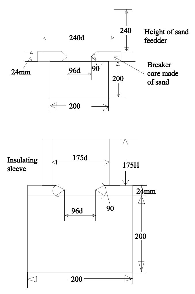
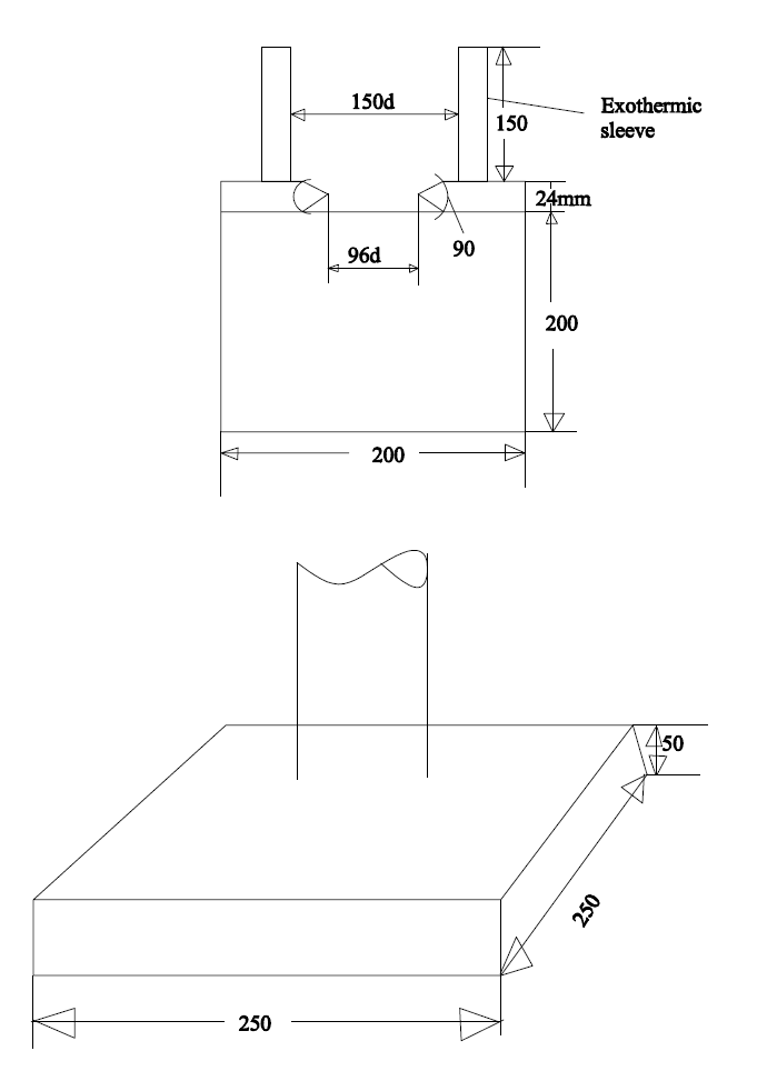
6) Make an Insulating Sleeve & an Exothermic Sleeves ( with the details
given) & Do the Cost- Benefit analysis.
109
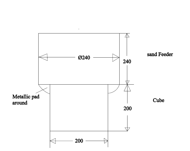
7) A Cube of 100 needs a Sand Feeder of 120 dia x 120 ht.
It needs 10.3 Kgs of Steel.( For FEEDER ONLY)
A Sand Sleeve with an OUTER ANNULAR SPACE was made.
(Shown in the SKETCHES )
The Feeder proper is 95 dia x 95 ht. The outer annular space has a dimension
of 135 OD x 115 ID x 85 ht. We got a SOUND CUBE Casting.
Let us do some calculation.
1) 0.785 x ( 1.35 + 1.15 ) ( 1.35 – 1.15 ) 0.85 x 7.6 = 2.54 Kgs.
Molten Steel requirement of annular space.
3
2) 0.785 x ( 0.95) x 7.6 = 5.11 Kgs ( Feeder Proper)
1+2 = 2.54 + 5.11 = 7.65 Kgs.
Savings in LIQUID STEEL is 10.3 Kgs – 7.65 Kgs = 2.65 Kgs.
Savings % 2.65 / 10.3 = 0.257 x 100 = 25.7 %
MEF = 120 dia / 95 dia = 1.26
The whole Purpose behind doing this Experiment was to make temperature
Gradient FLAT IN THE SAND ADJACENT TO LIQUID METAL IN
FEEDER FOR A WHILE.
If this experiment is repeated with INSULATING SLEEVE & EXOTHERMIC
SLEEVE. It would result in greater benefit.
TRY DOING IT. These kind of Sleeves are not available in the market & hence
You will have to make your own Sleeves.
8) Make a Sodium Silicate Core & pass a combination of CO2 gas and HOT
AIR. See the difference between this core & Conventional core. Do the Cost-
Benefit analysis.
9) Find out as to why Core made out of Sodium Silicate Sand & Bentonite
does not become FRIABLE.
10) Use dry BAMBOO Powder for making Insulating or Exothermic Sleeves.
11) Treat Al – 3 % Fe melt with SULPHUR to see if Fe can be removed as
FeS.
12) Find out how effective is PADDY HUSK as APC & also the Effectiveness
of Mixture of Paddy husk & dry BAMBOO powder.
13) Try Dry wood waste as an APC & also try to use Coconut shell powder as
APC. The Calorific Values of these have given in the text.
14) Check up the Effectiveness of Powdered COW DUNG CAKE as APC
110
15) Check up the effectiveness of a Sleeve made out of COW DUNG CAKE
POWDER.
16) Along with the stream of Steel or Grey Iron melt, add 1,2,3,4,5% Fine
STEEL SHOTS & Evaluate the Microstructure , Mechanical Properties &
Shrinkage pattern
17) For those of you , who want to work on Al –Si & get Primary Silicon ,
you need to add P-Cu ( 8 % P ) as Al2P3 is the nuclei for Primary Silicon.
For P to be available in the alloy, alloy must be free from Na, Ca , K & Ba
( Alkalis ) The cheapest Silicon available is CHINESE SILICON. But it
has alkaline elements. P being acidic, alkalines have to be removed before
adding P- Cu. Alkaline elements can be removed by TREATING the LIQUID
metal of Al-Si with ALUMINUM CHLORIDE ( Commercial Grade ).
This material, has a SUBLIMATION POINT of 190 degrees.
This material can be had from M/ s Kanoria Chemicals, Renukot, UP.
This material is Hygroscopic in nature , Heat the material to remove all
the moisture before use. This material does the TWIN work of removing
Alkaline elements & acts as a DEGASSER too.
THE PURPOSE BEHIND THIS LIST OF THINGS THAT CAN BE TRIED
OUT, IS ONLY TO IGNITE NEW IDEAS IN YOU
Books Referred to :
1) STEELS------R.W.K. Honeycombe.
2) THE PHYSICAL METALLURGY OF STEELS----Leslie.
3) THE APPLIED SCIENCE IN CASTING OF METALS—K. Strauss.
4) STEEL CASTINGS HAND BOOK--- Steel Founders’ Society Of America,
1970.
5) CAST IRON : PHYSICAL AND ENGINEERING PROPERTIES---
H. T. Angus.
6) THE DIRECTIONAL SOLIDIFICATION OF STEEL CASTINGS—
R.Wlodawer.
7) STRUCTURE OF METALS --- Barret & Masslaski.
8) INDIAN FOUNDRY JOURNAL--- April ,1986—Institute of Indian
Foundrymen.
9) P.R.Beeley----Foundry Technology.
111
PATTERN
Parting line, taken, should not lead to any casting problem. In the
First case a SHIFT in casting can occur, resulting in Casting rejection.
No such problem exists in second case.
112
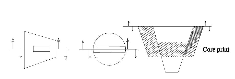
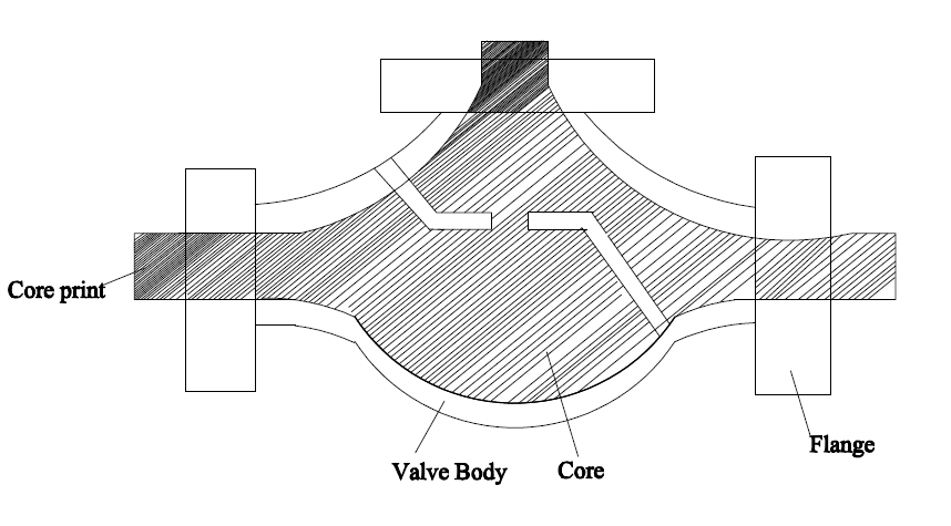
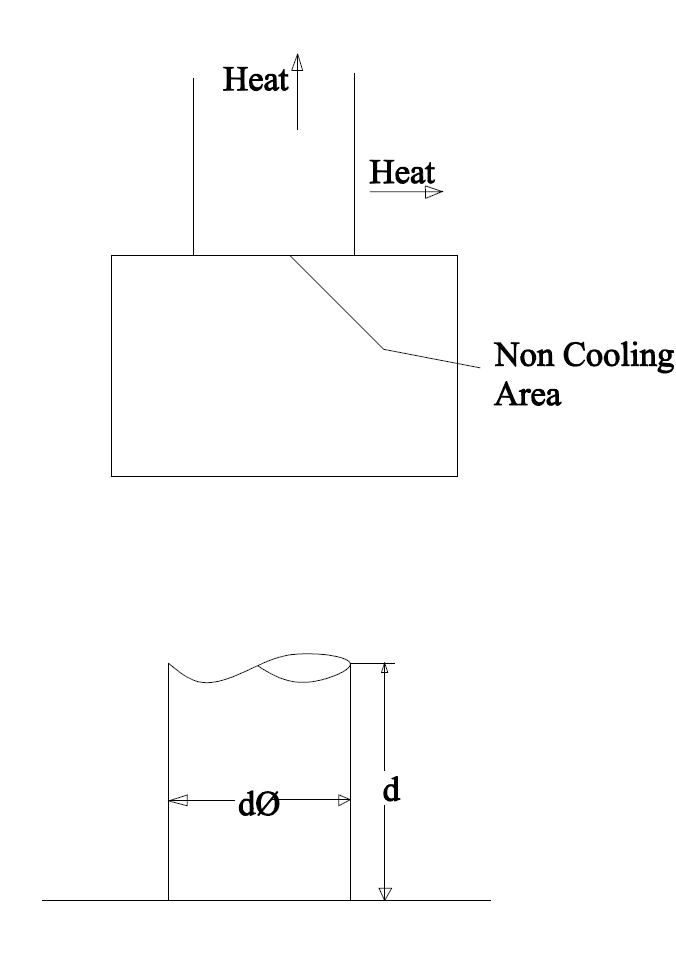
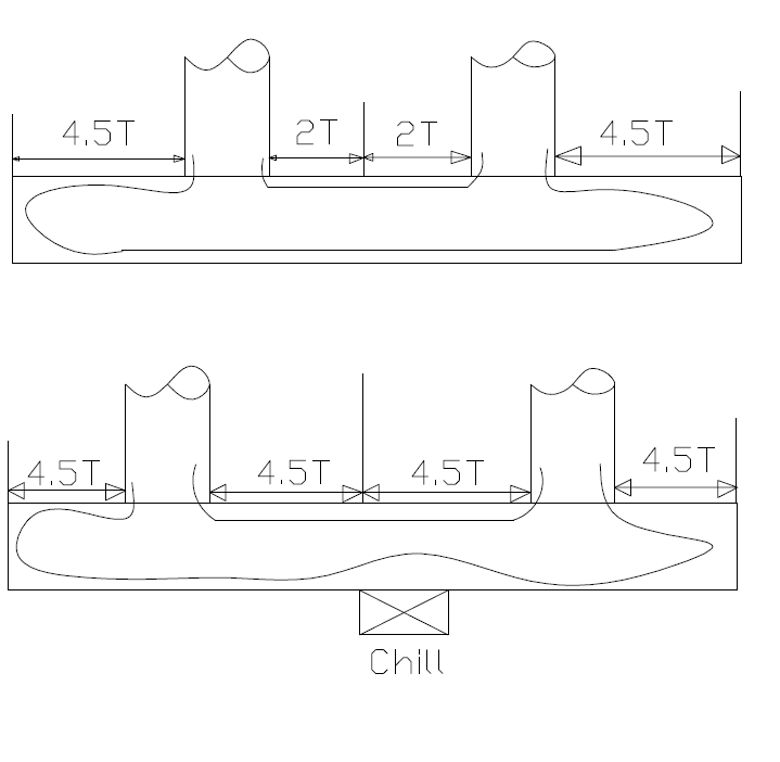
While designing a Casting, the Designer should always bear in MIND that
There are NO ISOLATED HOT SPOTS WHICH can not be FED.
113
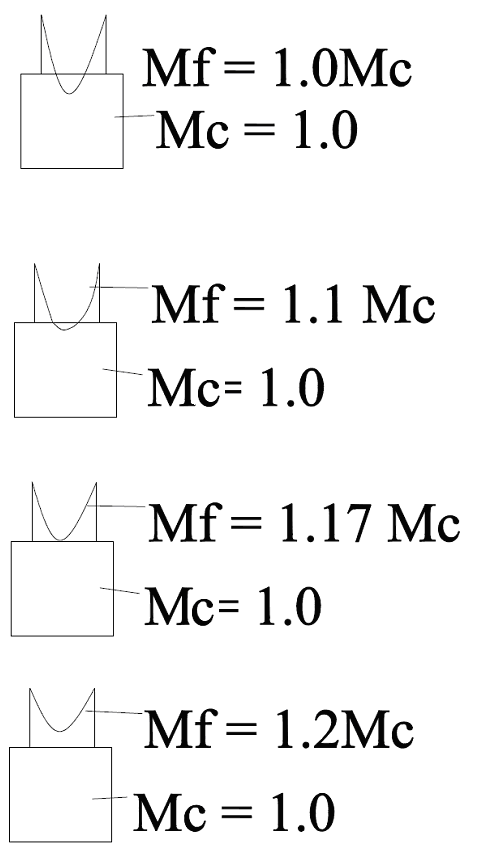
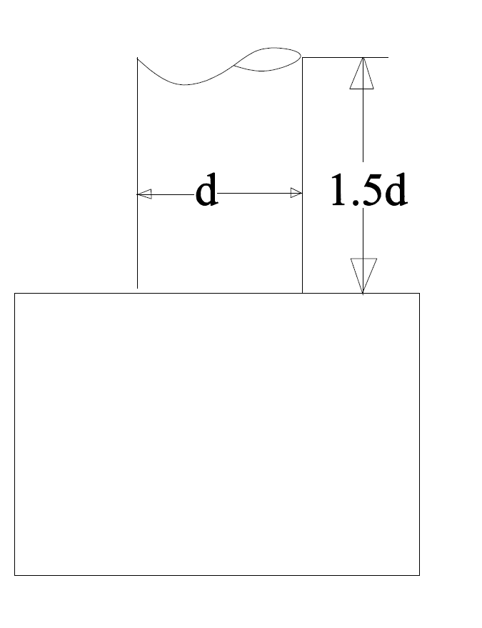
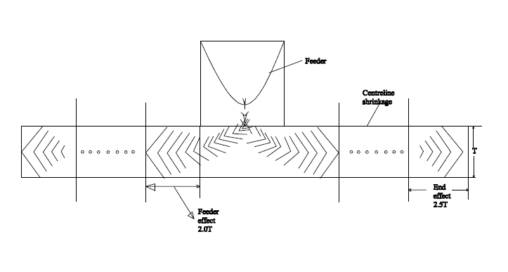
A TAPERED BAR IS AN IDEAL CASTING TO FEED FROM THE
POINT OF DIRECTIONAL SOLIDIFICATION.
METHODING
114
115
116
117
118
119
120
Centreline shrinkage is not acceptable in Radiography. Feeding system
Should be so designed that Centreline defect does not occur.
121
Reads:
6
Pages:
52
Published:
Feb 2025
"Microbial Minds: Are We Chemicals or Cosmic Consciousness?"explores the profound relationship between microorganisms and theessence of consciousness, challen...
Formats: PDF, Epub, Kindle, TXT

Reads:
69
Pages:
231
Published:
Mar 2024
Chemistry can be fun if you can think about it intuitively. Here with an unseen guide, we cover fundamental chemistry topics as we meet the great minds behind...
Formats: PDF, Epub, Kindle, TXT

Reads:
131
Pages:
24
Published:
Jan 2023
This mini e-book prompt guide is here to offer a comprehensive overview of the MidJourney instruction guide, enabling you to gain a better understanding of it...
Formats: PDF, Epub, Kindle, TXT

Reads:
34
Pages:
41
Published:
Dec 2022
Das fantastische und bahnbrechende Buch von Michael D. Elizondo - hier auf deutsch (2022). Der studierte Optiker Elizondo zeigt hier mit optisch-fachlichen Mi...
Formats: PDF, Epub, Kindle, TXT