Boolean Algebra is not the ordinary numerical algebra we know from high schools
but a totally new system called logic algebra.
As already seen before, Boolean algebra is ideal for the design and analysis of logic
circuits used in computers. It provides an economical and straight forward way of
describing computer circuitry and complicated switching circuits. As compared to
other mathematical tools of analysis and design, Boolean algebra has the advantages
of simplicity, speed and accuracy.
Unique Feature of Boolean Algebra.
Unlike in ordinay algebra, the variables used in Boolean algebra have a unique pro-
perty i.e. they can assume only one of the two possible values of 0 and 1. Each of
the values used in a logical or Boolean equation can assume only the value of 0 or 1.

African Virtual University 0
For example, in the logical equation A + B = C, each of the three variables A, B and
C can have only the value of either 0 or 1.
Laws of Boolean Algebra
Boolean algebra is a system of Mathematics based on logic. It has its own set of funda-
mental laws which are necessary for manipulating different Boolean expressions.
1. OR Laws
Law . A + 0 = A
Law 3. A + A = A
Law . A + 1 = 1
Law 4. A + A = 1
2. AND Laws
Law 5. A.0 = 0
Law 7.
A.A = A
Law A.1 = A
Law 8.
A.A = 0
3. Laws of complementation
Law . 0 = 1
Law 12. If A = 0, then A = 0
Law10. 1 = 0
Law . A = A
Law 11. If A = 0, then A = 1
4. Commutative laws
These laws allow change in the position of variables in OR and AND expres-
sions.
Law 14. A+ B = B + A Law 15. A.B = B.A
Laws 14 & 15 means that the order in which a combination of terms is performed
does not affect the final result of the combination.

African Virtual University 0
5. Associative laws
These laws allow removal of brackets from logical expression and regrouping of
variables.
Law 16. A (
) (
)
+ B + C = A + B + C
Law 17. ( A
) (
)
+ B + C + D = A + B + C + D
Law 18. A.(B.C ) = ( A.B).C
6. Distributive Laws
These laws permit factoring or multiplying out of an expression.
Law 19. A(B
)
+ C = AB + AC .
Law 20.
A
(
)(A ) .
+ BC = A + B
+ C
Law 21. A + A.B = A + B .
7. Absorptive Laws
These enable us to reduce a complicated logic expression to a simpler form by ab-
sorbing some of the terms into existing terms.
Law 22. A + AB = A
Law 23. A.( A + B) = A
Law 24. A. A + B
(
)= AB .

African Virtual University 0
Self Evaluation 4
1. Convert the binary fraction 0.111 into its decimal equivalent.
2 Convert 0.77 into its binary equivalent.
10
3. Convert 25.625 into its binary equivalent.
10
4. In the following conversions, comment on the answers that you get
i - 1101.0 and 11010.0 .
2
2
ii- 1101.0 and 110.10 .
2
2
5. Carry out the following binary subtraction
a. 1000 - 0001 .
2
2
b. 1001 - 0111 .
2
2
c. 1101 - 1010 .
2
2
6. Express the following hexadecimal numbers as binary numbers
(i) D8
(ii) 4E.
7. (a) Use references to a draw equivalent circuits for a NOT Gate and explain
how the circuit works.
(b)
A
B
X
C
(i)Find the Boolean equation for the output X.
(ii) Evaluate X when: A = 0, B = 1, C = 1 , and when A = 1, B = 1, C = 1
(c) Construct a logic operation for a NOR gate and explain how it works

African Virtual University 0
8.
i) Draw the logic circuit for the multiplexer shown in Fig. 4.11 (b)
ii) Write the logic equation which provides the switching function.
iii) The demultiplexer performs the inverse process of a multiplexer.
Write a short note on it.
9.
(i) Construct a Truth table for Fig. 4.13
(ii) Use Fig. 4.13 to describe how the four modes of operation: disabled or in-
hibited mode; set mode; reset or clear mode; and prohibited or not allowed
mode that can be obtained.
(iii) Draw a Clocked SR-Flip flop circuit and describe its mode of operations.

African Virtual University
Activity 5
Data Acquisition and Processes Control
You will require 20 hours to complete this activity. Only basic guidelines are provided
to help you go through the activity.
Specific Teaching and Learning Objectives
In this activity you will be required to:
(i) Explain the operation of a transducer in various modes (strain, light, piezo,
temp)
(ii) Explain and apply transducer signal conditioning processes and
(iii) Apply conditioned signal in digital form
Summary of the learning activity
In this activity, different types of transducers are considered in relation to how pro-
cessing of information is done. The discussion on processing of information is in
three parts: sensors, signal conditioning, and data acquisition. As an exam-
ple of sensors, piezoelectric sensor is discussed and expression for voltage
generated is derived. Under signal conditioning some of the following are
discussed: requirements for analogue-digital converters; signal isolation,
signal processing; removal of undesired signals. In addition, coversions of
sensor voltage, current, and resistance to voltage are discussed. The last
section of the activity considers data acquisition where the topics discussed
include anti-aliasing; sample and hold; analogue to digital conversion; and
system integrations. In some instances, some equations are derived and used
for numerical problems.

African Virtual University
List of REQUIRED readings
Reading 1 WIKIBOOKS
Complete reference:
http://en.wikibooks.org/wiki/Electronics/Boolean_Algebra. 5th October 2007.
Abstract: Topics covered include among others: formal mathematical operators,
Boolean algebra laws (Associativity, distributivity and commutivity).
Rationale. This provides basic reading materials on Boolean Algebra.
Reading 5 Sensors.
Reference: http://Soundlab.cs.princeton.ed/learning/tutorials/sensors/node19.html.
7th July 2007.
Abstract: the topics included are data acquisition (piezoelectric sensors, accelerom-
eter, force sensing resistors, microphones, biopotential sensors); Signal conditioning
(Requirements for A-D converters, voltage to voltage, current to voltage, resistance
to voltage,, capacitance to voltage); data acquisition(anti aliasing, analogue to digital
conversion, data acquisition systems).
Rationale. This reading provides good materials on this activity.
List of relevant MULTIMEDIA resources
Reference: http://images.google.co.uk/images?hl=en&q=Transducers&oe=UTF-
8&um=1&ie=UTF-8&sa=N&tab=wi. 4th October 2007.
Summary: Images of different types of transducers are provided.
Rationale: The resource is quite good as it provides one with information about the
different transducers.
Reference: http://images.google.co.uk/images?hl=en&q=sensors&oe=UTF-
8&um=1&ie=UTF-8&sa=N&tab=wi. 4th October 2007.
Summary: the resource provides different types of sensors.
Rational: The images reinforces the learning when one looks at them.
List of Relevant Useful Links
Title: Piezoelectricity
URL: http://en.wikipedia.org/wiki/Piezoelectricity. 4th October 2007.
Abstract: This provides useful reading on : materials, applications which includes
high voltage and power sources, sensors, actuators, piezoelectric motors, and crystal
classes.
Title: Transducers
URL:.http://en.wikipedia.org/wiki/Transducer”; 4th October 2007.
Abstract: This provides good reading about types of transducers, which include
among others: antenna, flourescent lamp, Hall effect sensor, rotary motor, vibration
powered generator, piezoelectric crystal and photodiodes.

African Virtual University
Activity 5.1
Operation of Transucers
In this activity you will be required to:
(i) Explain the operation of a transducer in various modes.
(ii) Explain and apply transducer signal conditioning processes.
(iii) Apply conditioned signal in digital form.
Since electronics is a course which is not taught much at school, this activity will
to a large extent provide you most of the basic information related to the different
concepts. However, you will be required to carry out extensive reading in order to
cover up the missing gaps. A number of references are given to you during your study,
but you should not limit yourself to only these references.
Activity 5.1.1
Definition of Transducers
A transducer is a device, usually electrical, electronic, electro-mechanical, elec-
tromagnetic, photonic, or photovoltaic that converts one type of energy to another
for various purposes including measurement or information transfer (for example,
pressure sensors). In a broader sense, a transducer is sometimes defined as any device
that converts a signal from one form to another.
Activity 5.1.2
Processing of information
In this section, you will learn how processing of information is done. This in rela-
tion to the key principal areas. The path through which information are processed
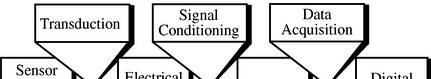
requires three parts: sensors, signal conditioning, and data acquisition as depicted in Fig.5.1.
Figure 5.1 The three parts through which information is processed

African Virtual University
Before, discussing the three parts through which information is processed, let us first
look at the types of transducers.
Types of transducers
The types of transducers are given as follows:
1. Electromagnetic:
- Antenna- converts electromagnetic waves into electric current and vice-
versa.
- Cathode ray tube (CRT) - converts electrical signals into visual form.
- Flourescent lamp, light bulb - converts electrical power into visible light.
- Magnetic cartridge - converts motion into electrical form.
- Light-dependent resistor (LDR) - converts changes in light levels into resis-
tance changes.
- Tape head - converts changing magnetic fields into electrical form.
- Hall effect sensor - converts a magnetic field level into electrical form.
2. Electrochemical:
- pH probe.
- Electro-galvanic fuel cell.
3. Electromechanical:
- Rotary motor, linear motor.
- Potentiometer when used for measuring position.
- Load cell converts force to mV/V electrical signal using strain gauges.
- Strain gauge.
- Switch.
4. Electroacoustic:
- Geophone - converts ground movement (displacement) into voltage.
- Hydrophone - converts changes in water pressure into an electrical form.
- Loudspeaker, earphone - converts changes in electrical signals into
acoustic form.
- Microphone - converts changes in air pressure into an electrical signal.
- Piezoelectric crystal - converts pressure changes into electrical form.
- Laser diode, light-emitting diode - convert electrical power into forms of
light.
- Photodiode. Photoresistor, phototransistor, photomultiplier tube - converts
changing light levels into electrical form.

African Virtual University
5. Electrostatic:
- Electrometer.
- Liquid crysral dsiplay (LCD).
6. Thermoelectric:
- RTD Resistance Temperature Detector.
- Thermocouple.
- Thermistor (includes PTC resistor and NTC resistor).
Task 5.1 Further Reading and Note making
You are required to use the references, «http://en.wikipedia.org/wiki/Transducer»; 8th
October 2007.; http://soundlabs.princeton.edu/learning tutorials/sensors/node7, 12th
August 2007., to make brief notes. You need to use the links within the reference in
order to enrich the notes.
(a) Explain the operation of a transducer in the following modes
• Strain
• Light,
• Piezo and
• Temperature
Activity 5.1.3
Brief Notes on sensor, signal conditioning and Data
acquisition
In this section, the three stages of processing information in Fig. 5.1 are briefly dis-
cussed as follows. Most of the concepts are provided, thus what you need to do is to
concentrate on understanding the concepts provided hereunder.
(i)The Sensor
Sensors can be categorized by the underlying physics of their operation, although one
physical principle can be used to explain many different phenomena. For example,
the piezoelectric effect can measure force, flexure, acceleration, heat, and acoustic
vibrations. However, one phenomenon can also be measured by many physical
principles. For example, sound waves can be explained by the piezoelectric effect,
capacitance, electromagnetic field effects, and changes in resistance.

African Virtual University
(ii)Signal Conditioning
The information from a sensor must be changed to a form appropriate for input into
the data acquisition system. This means changing the sensors output to a voltage (if it
isn’t already), modifying the sensors dynamic range to maximize the accuracy of the
data acquisition system, removing unwanted signals, and limiting the sensor’s spec-
trum. In some cases, analog signal processing (both linear and nonlinear) are desired to alleviate processing load from the data acquisition system and the computer.
(iii)Data Acquisition
The analog and continuous time signals measured by the sensor and modified by
the signal conditioning circuitry must be converted into the form a computer can
understand. This is what is referred to here as data acquisition.
Activity 5.1.4
Sensors
In this activity you will explain the operation of some of the sensors:
1. Pizoelectric sensors; and force sensing resistor; and microphones.
2. The notes provided must be supplemented at all times.
Piezoelectric Sensors
The Piezoelectric effect is an effect in which energy is converted between mechani-
cal and electrical forms. When a pressure is applied to a piezoelectric, the resulting
mechanical deformation results in an electrical charge. For example, Piezoelectric
microphones turns acoustical pressure into a voltage. Alternatively, when an electrical
charge is applied to a polarized crystal, the crystal undergoes a mechanical deformation
which can in turn create an acoustical pressure. (Read more about this).
How a voltage is created in a polarized crystal
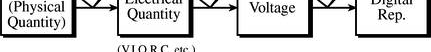
Figure 5.2 Internal Structure of an electret
Solids which have permanent electrical polarization are called electrets, Fig. 5.2.
Similar permanent polarization is also observed in crystals where, each cell of the
crystal has an electric dipole, oriented such that the electric dipoles are aligned. But,

African Virtual University
this results in excess surface charge which attracts free charges from the surrounding
atmosphere which makes the crystal electrically neutral. If a sufficient force is applied
to piezoelectric crystal, the deformation which takes place disrupts the orientation
of the electrical dipoles and a situation where charge is not completely canceled is
created. This results in a temporary excess of surface charge, which subsequently
manifests as a voltage that is developed across the crystal.
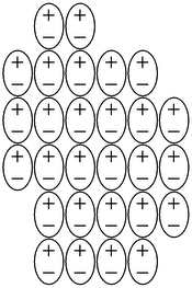
Figure 5.3 A sensor based on the piezoelectric effect
If the surface the charge on a crystal is known, this physical principle is used to make
a sensor which measures force. A force sensor is made of a capacitor formed by
sandwiching a piezoelectric crystal between two metal plates as shown in Fig. 5.3.
When an external force acts on a crystal, a charge, which is a function of the applied
force is created due to defomation of the crystal. This charge results into a voltage,
V given by Eq. 5.1
Q
V = f 5.1
( )
C
Q is the charge resulting from a force f, and C is the capacitance of the device.
f
As described above, piezoelectric crystals act as transducers which turn force, or
mechanical stress into electrical charge which in turn can be converted into a voltage.
Conversely, if one applies a voltage to the plates of the system in Fig. 5.3, the resul-
tant electric field causes the internal electric dipoles to re-align which would cause
a deformation of the material. An example of this is that piezoelectric transducers
find use both as speakers (voltage to mechanical) and microphones (mechanical to
electrical).
Task 5.2 Further reading and Note making
Use Compulsory Reading 5, and other references to write notes explaining the
principles and operation of
(a) Force sensing resistors.
(b) Accelerometer (Analog Devices ADXL50).
(c) Microphones.

African Virtual University
Activity 5.1. Signal Conditioning
Requirements for A-D converters
The primary purpose for the analog signal conditioning circuitry is to modify the
sensor output into a form that can be optimally converted to a discrete time digital