Convex mirror lets motorists see around a corner.
The passenger-side mirror on a car is typically a convex mirror. In some countries, these are labelled with the safety warning "Objects in mirror are closer than they appear", to warn the
driver of the convex mirror's distorting effects on distance perception.
Convex mirrors are used in some automated teller machines as a simple and handy security feature, allowing the users to see what is happening behind them. Similar devices are sold to be
attached to ordinary computer monitors.
22

Some camera phones use convex mirrors to allow the user correctly aim the camera while taking
[] Concave mirrors
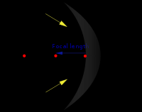
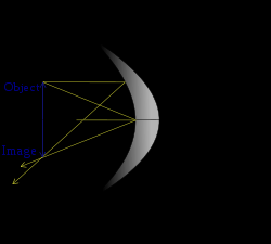
A concave mirror diagram showing the focus, focal Length, centre of curvature, principal axis,
etc.
A concave mirror, or converging mirror, has a reflecting surface that bulges inward (away
from the incident light). Concave mirrors reflect light inward to one focal point, therefore they
are used to focus light. Unlike convex mirrors, concave mirrors show different image types
depending on the distance between the object and the mirror.
These mirrors are called "converging" because they tend to collect light that falls on them,
refocusing parallel incoming rays toward a focus. This is because the light is reflected at different angles, since the normal to the surface differs with each spot on the mirror.
[] Image
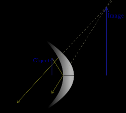
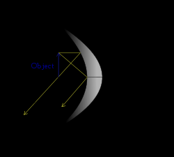
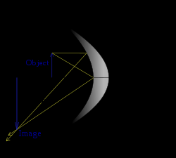
Effect on image of object's position relative to mirror focal point
Object's
position ( S),
Image
Diagram
focal point ( F)
23
S < F
Virtual
(Object
Upright
between focal
Magnified (larger)
point and
mirror)
the image is formed at infinity.
S = F
(Object at
(Note that the reflected light rays are
focal point) parallel and do not meet the others. In
this way, no image is formed or more
properly the image is formed at infinity.)
Real
Inverted (vertically)
F < S < 2 F
Magnified (larger)
24
S = 2 F
Real
(Object at
Inverted (vertically)
centre of
Same size
curvature)
Real
Inverted (vertically)
S > 2 F
Diminished (smaller)
[] Mirror shape
Most curved mirrors have a spherical profile. These are the simplest to make, and it is the best
shape for general-purpose use. Spherical mirrors, however, suffer from spherical aberration.
Parallel rays reflected from such mirrors do not focus to a single point. For parallel rays, such as
those coming from a very distant object, a parabolic reflector can do a better job. Such a mirror can focus incoming parallel rays to a much smaller spot than a spherical mirror can.
See also: Toroidal reflector
[] Analysis
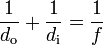
[] Mirror equation and magnification
The Gaussian mirror equation relates the object distance ( d o) and image distances ( d i) to the focal length ( f):
.
25
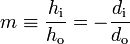

The magnification of a mirror is defined as the height of the image divided by the height of the object:
.
The negative sign in this equation is used as a convention. By convention, if the magnification is positive, the image is upright. If the magnification is negative, the image is inverted (upside
down).
[] Ray tracing
Main article: Ray tracing (physics)
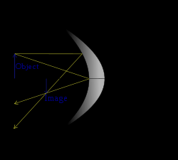
The image location and size can also be found by graphical ray tracing, as illustrated in the
figures above. A ray drawn from the top of the object to the surface vertex (where the optical
axis meets the mirror) will form an angle with that axis. The reflected ray has the same angle to the axis, but is below it (See Specular reflection).
A second ray can be drawn from the top of the object passing through the focal point and
reflecting off the mirror at a point somewhere below the optical axis. Such a ray will be reflected
from the mirror as a ray parallel to the optical axis. The point at which the two rays described above meet is the image point corresponding to the top of the object. Its distance from the axis
defines the height of the image, and its location along the axis is the image location. The mirror
equation and magnification equation can be derived geometrically by considering these two rays.
[] Ray transfer matrix of spherical mirrors
Further information: Ray transfer matrix analysis
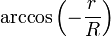
The mathematical treatment is done under the paraxial approximation, meaning that under the first approximation a spherical mirror is a parabolic reflector. The ray matrix of a spherical mirror is shown here for the concave reflecting surface of a spherical mirror. The C element of
the matrix is
, where f is the focal point of the optical device.
26
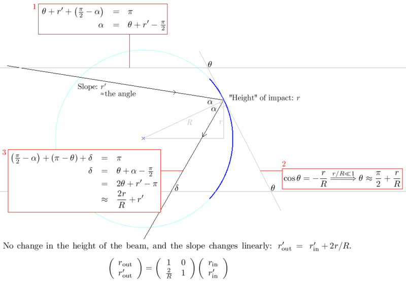
Boxes 1 and 3 feature summing the angles of a triangle and comparing to π radians (or 180°).
Box 2 shows the Maclaurin series of
up to order 1. The derivations of the ray
matrices of a convex spherical mirror and a thin lens are very similar.
Brewster's angle
From Wikipedia, the free encyclopedia
Jump to: navigation, search
27

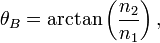
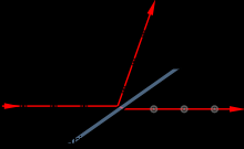
An illustration of the polarization of light which is incident on an interface at Brewster's angle.
Brewster's angle (also known as the polarization angle) is an angle of incidence at which light with a particular polarization is perfectly transmitted through a surface, with no reflection. The angle at which this occurs is named after the Scottish physicist, Sir David Brewster (1781–1868).
[] Explanation
When light moves between two media of differing refractive index, generally some of it is
reflected at the boundary. At one particular angle of incidence, however, light with one particular polarization cannot be reflected. This angle of incidence is Brewster's angle, θB. The polarization
that cannot be reflected at this angle is the polarization for which the electric field of the light waves lies in the same plane as the incident ray and the surface normal (i.e. the plane of incidence). Light with this polarization is said to be p-polarized, because it is parallel to the
plane. Light with the perpendicular polarization is said to be s-polarized, from the German
senkrecht—perpendicular. When unpolarized light strikes a surface at Brewster's angle, the
reflected light is always s-polarized. Although 's' and 'p' polarization states were not named for
this convention, it may be convenient to remember that 's' polarized light will "skip" off a
Brewster boundary and 'p' polarized light will "plunge" through.
The physical mechanism for this can be qualitatively understood from the manner in which
electric dipoles in the media respond to p-polarized light. One can imagine that light incident on the surface is absorbed, and then reradiated by oscillating electric dipoles at the interface
between the two media. The polarization of freely propagating light is always perpendicular to
the direction in which the light is travelling. The dipoles that produce the transmitted (refracted)
light oscillate in the polarization direction of that light. These same oscillating dipoles also
generate the reflected light. However, dipoles do not radiate any energy in the direction along
which they oscillate. Consequently, if the direction of the refracted light is perpendicular to the
direction in which the light is predicted to be specularly reflected, the dipoles will not create any reflected light. Since, by definition, the s-polarization is parallel to the interface, the
corresponding oscillating dipoles will always be able to radiate in the specular-reflection
direction. This is why there is no Brewster's angle for s-polarized light.
28
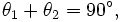
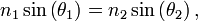

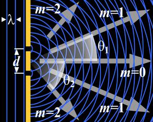
With simple trigonometry this condition can be expressed as:
where θ1 is the angle of incidence and θ2 is the angle of refraction.
Using Snell's law,
we can calculate the incident angle θ =θ
1
B at which no light is reflected:
Rearranging, we get:
where n 1 and n 2 are the refractive indices of the two media. This equation is known as Brewster's law.
Note that, since all p-polarized light is refracted (i.e. transmitted), any light reflected from the
interface at this angle must be s-polarized. A glass plate or a stack of plates placed at Brewster's
angle in a light beam can thus be used as a polarizer.
For a glass medium ( n ≈1.5) in air ( ≈1), Brewster's angle for visible light is approximately 56°
2
n 1
to the normal while for an air-water interface ( n ≈1.33), it's approximately 53°. Since the
2
refractive index for a given medium changes depending on the wavelength of light, Brewster's
angle will also vary with wavelength.
The phenomenon of light being polarized by reflection from a surface at a particular angle was
first observed by Etienne-Louis Malus in 1808. He attempted to relate the polarizing angle to the refractive index of the material, but was frustrated by the inconsistent quality of glasses available
at that time. In 1815, Brewster experimented with higher-quality materials and showed that this
angle was a function of the refractive index, defining Brewster's law.
Although Brewster's angle is generally presented as a zero-reflection angle in textbooks from the
late 1950s onwards, it truly is a polarizing angle. The concept of a polarizing angle can be
extended to the concept of a Brewster wavenumber to cover planar interfaces between two linear
bianisotropic materials.
[] Applications
29


Polarized sunglasses use the principle of Brewster's angle to reduce glare from the sun reflecting off horizontal surfaces such as water or road. In a large range of angles around Brewster's angle
the reflection of p-polarized light is lower than s-polarized light. Thus, if the sun is low in the sky reflected light is mostly s-polarized. Polarizing sunglasses use a polarizing material such as
polaroid film to block horizontally-polarized light, preferentially blocking reflections from horizontal surfaces. The effect is strongest with smooth surfaces such as water, but reflections
from road and the ground are also reduced.
Photographers use the same principle to remove reflections from water so that they can
photograph objects beneath the surface. In this case, the polarizing filter camera attachment can be rotated to be at the correct angle (see figure).
Photographs taken of mudflats with a camera polarizer filter rotated to two different angles. In
the first picture, the polarizer is rotated to maximize reflections, and in the second, it is rotated
90° to minimize reflections - almost all reflected sunlight is eliminated.
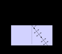
[] Brewster windows
A Brewster window
Gas lasers typically use a window tilted at Brewster's angle to allow the beam to leave the laser tube. Since the window reflects some s-polarized light but no p-polarized light, the gain for the s 30


polarization is reduced but that for the p polarization is not affected. This causes the laser's
output to be p polarized, and allows lasing with no loss due to the window.[1]
Diffraction
From Wikipedia, the free encyclopedia
Jump to: navigation, search
The intensity pattern formed on a screen by diffraction from a square aperture
Diffraction
31
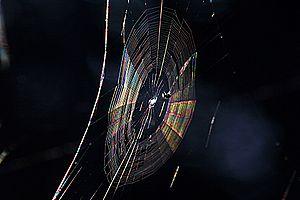

Colors seen in a spider web are partially due to diffraction, according to some analyses.[1]
Diffraction refers to various phenomena which occur when a wave encounters an obstacle. It is
described as the apparent bending of waves around small obstacles and the spreading out of
waves past small openings. Similar effects are observed when light waves travel through a
medium with a varying refractive index or a sound wave through one with varying acoustic
impedance. Diffraction occurs with all waves, including sound waves, water waves, and
electromagnetic waves such as visible light, x-rays and radio waves. As physical objects have wave-like properties (at the atomic level), diffraction also occurs with matter and can be studied
according to the principles of quantum mechanics.
While diffraction occurs whenever propagating waves encounter such changes, its effects are
generally most pronounced for waves where the wavelength is on the order of the size of the diffracting objects. If the obstructing object provides multiple, closely-spaced openings, a
complex pattern of varying intensity can result. This is due to the superposition, or interference,
of different parts of a wave that traveled to the observer by different paths (see diffraction
The formalism of diffraction can also describe the way in which waves of finite extent propagate
in free space. For example, the expanding profile of a laser beam, the beam shape of a radar
antenna and the field of view of an ultrasonic transducer are all explained by diffraction theory.
[] Examples
32
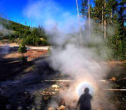


Solar glory at the steam from hot springs. A glory is an optical phenomenon produced by light backscattered (a combination of diffraction, reflection and refraction) towards its source by a cloud of uniformly-sized water droplets.
The effects of diffraction can be regularly seen in everyday life. The most colorful examples of
diffraction are those involving light; for example, the closely spaced tracks on a CD or DVD act
as a diffraction grating to form the familiar rainbow pattern we see when looking at a disk. This principle can be extended to engineer a grating with a structure such that it will produce any
diffraction pattern desired; the hologram on a cr card is an example. Diffraction in the
atmosphere by small particles can cause a bright ring to be visible around a bright light source like the sun or the moon. A shadow of a solid object, using light from a compact source, shows
small fringes near its edges. The speckle pattern which is observed when laser light falls on an optically rough surface is also a diffraction phenomenon. All these effects are a consequence of
the fact that light propagates as a wave.
Diffraction can occur with any kind of wave. Ocean waves diffract around jetties and other obstacles. Sound waves can diffract around objects, which is why one can still hear someone
calling even when hiding behind a tree.[2] Diffraction can also be a concern in some technical applications; it sets a fundamental limit to the resolution of a camera, telescope, or microscope.
[] History
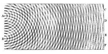
Thomas Young's sketch of two-slit diffraction, which he presented to the Royal Society in 1803
33


The effects of diffraction

Reads:
0
Pages:
284
Published:
May 2025
This comprehensive volume contains over 1,300 multiple-choice questions, each meticulously answered and enriched with detailed feedback. What makes it stand o...
Formats: PDF, Epub, Kindle, TXT

Reads:
8
Pages:
52
Published:
Feb 2025
"Microbial Minds: Are We Chemicals or Cosmic Consciousness?"explores the profound relationship between microorganisms and theessence of consciousness, challen...
Formats: PDF, Epub, Kindle, TXT

Reads:
73
Pages:
231
Published:
Mar 2024
Chemistry can be fun if you can think about it intuitively. Here with an unseen guide, we cover fundamental chemistry topics as we meet the great minds behind...
Formats: PDF, Epub, Kindle, TXT

Reads:
132
Pages:
24
Published:
Jan 2023
This mini e-book prompt guide is here to offer a comprehensive overview of the MidJourney instruction guide, enabling you to gain a better understanding of it...
Formats: PDF, Epub, Kindle, TXT