Figure 2.3 Discovery and registration process
P.17
[IP Telephony Cookbook] / Technological Background
After the endpoint discovers the location of the gatekeeper, it tries to register itself (RRQ). Such a registration includes (among other information):
- The addresses of the endpoint - for a terminal, this may be the user ids or telephone numbers.
An endpoint may have more than one address. In theory it is possible that addresses belong to different users to enable multiple users to share a single phone - in practice, this depends on the phones and the gatekeeper implementation;
- Prefixes - if the registering endpoint is a gateway it may register number prefixes instead of addresses;
- Time to live - an endpoint may request how long the registration will last.This value can be overwritten by gatekeeper policies.
The gatekeeper checks the requested registration information and confirms the (possibly modified) values (RCF). It may also reject a registration request because of, for example, invalid addresses. In the case of a confirmation, the gatekeeper assigns a unique identifier to the endpoint, which will be used in subsequent requests to indicate that the endpoint is still registered.
2.2.1.3.1 Addresses and registrations
H.323 defines and utilises several address types.The one most commonly used and derived from the PSTN world is the dialled digit address, which is defined as a number dialled by the endpoint.
It does not include further information (e.g., about the dial plan) and needs to be interpreted by the server.The server might convert the dialled number into a party number that includes information about the type of number and the dial plan.
To provide alphanumeric or name dialling, H.323 supports H.323-IDs that represent either usernames or e-mail-like addresses, or the more general approach of URL-ID which represent any kind of URL.
Unlike SIP addresses, an H.323 address can only be registered by one endpoint (per zone), so a call to that address only resolves to a single endpoint.To call multiple destinations simultaneously in H.323 requires a gatekeeper that actively maps a single address to multiple different addresses and tries to contact them in sequence.
2.2.1.3.2 Updating registrations
A registration expires after a defined time and must therefore be refreshed i.e., kept alive by subsequent registrations which include the previously-assigned endpoint identifier.To reduce the registration overhead of regular registrations, H.323 supports KeepAlive registrations that contain only the previously-assigned endpoint identifier. Of course, these registrations may only be sent if the registration information is unchanged.
Endpoints requesting the registration of large numbers of addresses would exceed the size of a UDP packet, so H.323v4 supports Additive Registration, a mechanism that allows an endpoint to send multiple registration requests (RRQ) in which the addresses do not replace existing registrations but are submitted in addition to them.
P.18
[IP Telephony Cookbook] / Technological Background
{ 2.2.1.4 Signalling models
Call signalling messages and H.245 control messages may be exchanged either end-to-end between calling party and called party or through a gatekeeper. Depending on the role the gatekeeper plays in the call signalling and in the H.245 signalling, the H.323 specification foresees three different types of signalling models:
- Direct signalling
With this signalling model, only H.225.0 RAS messages are routed through the gatekeeper while the other logical channel messages are directly exchanged between the two endpoints;
- Gatekeeper-routed call signalling
With this signalling model, H.225.0 RAS and H.225.0 call signalling messages are routed through the gatekeeper, while the H.245 Conference Control messages are directly exchanged between the two endpoints;
- Gatekeeper-routed H.245 control, H.225.0 RAS and H.225.0
Call signalling and H.245 Conference Control messages are routed through the gatekeeper and only the media streams are directly exchanged between the two endpoints.
The following sub-sections detail each signalling model.The figures displayed in this section apply both to the use of a single gatekeeper and to the use of a gatekeeper network. Since the signalling model is decided by the configuration of the endpoint's gatekeeper and applies to all the messages the gatekeeper handles, the extensions to the multiple gatekeeper are straightforward (they simply apply the definition of the signalling model described in the itemised list above to each gatekeeper involved), except for the location of zone-external targets (described later in the
‘Locating zone external targets’ section). Message exchanges in any of the figures in this section are not reported, as the figures are intended to remain bounded in the ellipse where the H.323
Gatekeeper is depicted. Also, it is described in the ‘Locating zone external targets’ section. Please note that there is no indication about the call termination in the sub-section of each signalling model. Please refer to the ‘Communication phases’ Section for details.
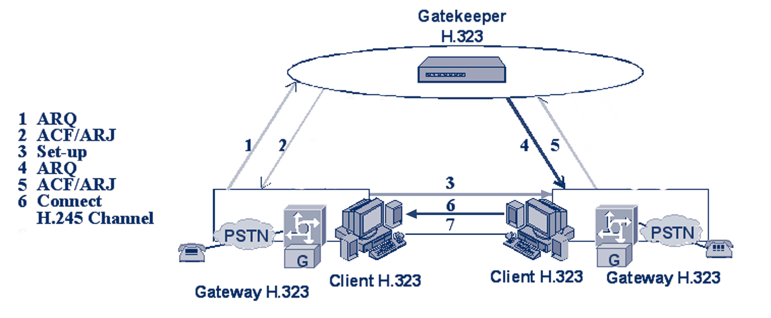
The direct signalling model is depicted in Figure 2.4. In this model, the H.225.0 Call Signalling and H.245 Conference Control messages are exchanged directly between the call terminals. As shown in the figure, the communication starts with an ARQ (Admission ReQuest) message sent by the calling party (which may be either a terminal or a gateway) to the gatekeeper.The ARQ message is used by the endpoint to request access to the packet-based network from the gatekeeper, which either grants the request with an ACF (Admission ConFirm) or denies it with an ARJ (Admission ReJect). If an ARJ is issued, the call is terminated. After this first step, the call signalling part of the call begins with the transmission of the SET UP message from the calling party to the called party.The transport address of the SET UP message (and of all the H.225.0 call signalling messages) is retrieved by the calling party from the destCallSignalAddress field carried inside the ACF received. In the case of the direct signalling model, it is the address of the destination endpoint. Upon receiving the SET UP message, the called party starts its H.225.0
RAS procedure with the gatekeeper. If successful, a CONNECT message is sent back to the calling party to indicate acceptance of the call. Before sending the CONNECT message, two other messages may be sent from the called party to the calling party (those two messages are not depicted in the figure since we have reported only mandatory messages): P.19

[IP Telephony Cookbook] / Technological Background
- ALERTING message
This message may be sent by the called user to indicate that called user alerting has been initiated (in everyday terms, the ‘phone is ringing’);
- CALL PROCEEDING message
This message may be sent by the called user to indicate that requested call establishment has been initiated and no more call-establishment information will be accepted.
Figure 2.4 Direct signalling model
The CONNECT message closes the H.225.0 call signalling part of the call and makes the terminals starting the H.245 conference control one. In such call mode, the H.245 Conference Control messages are exchanged directly between the two endpoints (the correct ‘h245Address’
was retrieved from the CONNECT message itself).The procedures started with the H.245
Conference Control channel are used to:
- allow the exchange of audiovisual and data capabilities, with the TERMINAL CAPABILITY
messages;
- request the transmission of a particular audiovisual and data mode, with the LOGICAL
CHANNEL SIGNALLING messages;
- manage the logical channels used to transport the audiovisual and data information;
- establish which terminal is the master terminal and which is the slave terminal for the purposes of managing logical channels, with the MASTER SLAVE DETERMINATION messages;
- carry various control and indication signals;
- control the bit rate of individual logical channels and the whole multiplex, with the MULTIPLEX TABLE SIGNALLING messages;
- measure the round trip delay, from one terminal to the other and back, with the ROUND
TRIP DELAY messages.
Once the H.245 conference control messages are exchanged, the two endpoints have all the necessary information to open the media streams.
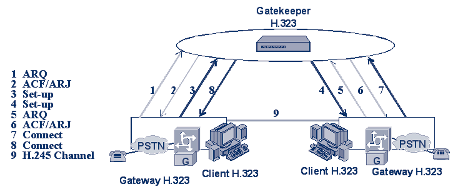
2.2.1.4.2 Gatekeeper-routed call signalling model
The gatekeeper-routed call signalling model is depicted in Figure 2.5. In this model, the H.245
Conference Control messages are exchanged directly between the call termination clients.With each call, the communication starts with an ARQ message (Admission ReQuest) sent by the calling party to its gatekeeper.The ARQ message is used by the endpoint to request access to the P.20

[IP Telephony Cookbook] / Technological Background
packet-based network from the gatekeeper, which either grants the request with an ACF
(Admission ConFirm) or denies it with an ARJ (Admission ReJect). After this first step, the call signalling part of the call begins with the transmission of the SET UP message from the calling party to its gatekeeper.The transport address of the SET UP message (and of all the H.225.0 call signalling messages) is retrieved by the calling party from the destCallSignalAddress field, carried inside the ACF received. In the case of the gatekeeper-routed call signalling model, it is the address of the gatekeeper itself.The SET UP message is then forwarded by the gatekeeper (or by the gatekeeper network) to the called endpoint. Upon receiving the SET UP message, the called party starts its H.225.0 RAS procedure with its gatekeeper. If successful, a CONNECT message is sent to indicate acceptance of the call. Because of the call model, this message is also sent to the called endpoint's gatekeeper which is in charge of forwarding it to the calling party endpoint (either directly or using the gatekeeper network). Before sending the CONNECT message, two other messages may be sent from the called party to its gatekeeper (those two messages are not depicted in the figure since only mandatory messages are reported):
- ALERTING message
This message may be sent by the called user to indicate that called user alerting has been initiated (in everyday terms, the ‘phone is ringing’);
- CALL PROCEEDING message
This message may be sent by the called user to indicate that requested call establishment has been initiated and no more call establishment information will be accepted.
Figure 2.5 Gatekeeper-routed call signalling model
The two optional messages listed above are then forwarded by the gatekeeper (or by the gatekeeper network) to the calling party. After receiving the CONNECT message, the calling party starts the H.245 Conference Control channel procedures directly with the called party (the correct h245Address was retrieved from the CONNECT message itself).The scope of the H.245
Conference Control channel procedure is the same as is detailed above. Please refer to the ‘Direct signalling model’ Section for details.
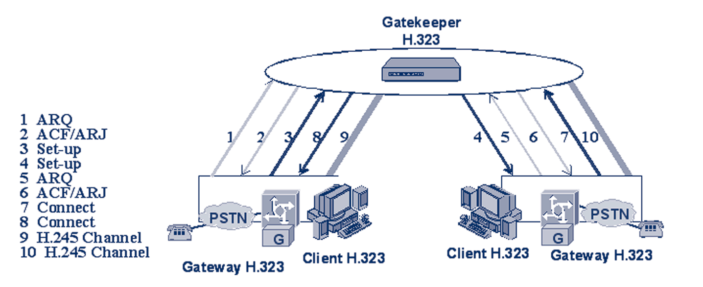
2.2.1.4.3 Gatekeeper-routed H.245 control model
The gatekeeper-routed H.245 control model is depicted in Figure 2.6. In this model, only the media streams are exchanged directly between the call termination clients. For each call, the communication starts with an ARQ (Admission ReQuest) message sent by the calling party to its gatekeeper.The ARQ message is used by the endpoint to be allowed to access the packet-based P.21
[IP Telephony Cookbook] / Technological Background
network by the gatekeeper, which either grants the request with an ACF (Admission ConFirm) or denies it with an ARJ (Admission ReJect). After this first step, the call signalling part of the call begins with the transmission of the SET UP message from the calling party to its gatekeeper.
The transport address of the SET UP message (and of all the H.225.0 call signalling messages) is retrieved by the calling party from the destCallSignalAddress field carried inside the ACF
received. In the case of gatekeeper-routed H.245 control model, it is the address of the gatekeeper itself.The SET UP message is then forwarded by the gatekeeper (or by the gatekeeper network) to the called endpoint. Upon receiving the SET UP message, the called party starts its H.225.0
RAS procedure with its gatekeeper. If successful, a CONNECT message is sent to indicate acceptance of the call. Because of the call model, this message is also sent to the called endpoint's gatekeeper, which is in charge of forwarding it to the calling party endpoint (either directly or using the gatekeeper network). Before sending the CONNECT message, two other messages may be sent from the called party to its gatekeeper (those two messages are not depicted in the figure since only mandatory messages are reported):
- ALERTING message
This message may be sent by the called user to indicate that called user alerting has been initiated (in everyday terms, the ‘phone is ringing’);
- CALL PROCEEDING message
This message may be sent by the called user to indicate that requested call establishment has been initiated and no more call establishment information will be accepted.
Figure 2.6 Gatekeeper-routed H.245 control model
The two optional messages listed above are then forwarded by the gatekeeper (or by the gatekeeper network) to the calling party. After receiving the CONNECT message, the calling party starts the H.245 Conference Control channel procedures with its gatekeeper (the correct h245Address was retrieved from the CONNECT message itself). All of the H.245 channel messages are then exchanged by the endpoints with their gatekeeper (or gatekeepers). It is the gatekeeper (or gatekeeper network) which takes care of forwarding them up to the remote endpoint as foreseen by the gatekeeper-routed H.245 control model.The scope of the H.245
Conference Control channel procedure is the same as is detailed above. Please refer to the ‘Direct signalling model’ Section for details.
P.22
[IP Telephony Cookbook] / Technological Background
{ 2.2.1.5 Communication phases
In a H.323, communication may be identified in five different phases:
- Call set up;
- Initial communication and capability exchange;
- Establishment of audiovisual communication;
- Call services;
- Call termination.
2.2.1.5.1 Call setup
Recommendation H.225.0 defines the call setup messages and procedures detailed here.The recommendation foresees that requests for bandwidth reservation should take place at the earliest possible phase. Unlike other protocols, there is no explicit synchronisation between two endpoints during the call setup procedure (two endpoints can send a SET UP message to each other at exactly the same time). Actions to be taken when problems of synchronisation during the exchange of SET UP messages arise are resolved by the application itself. Applications not supporting multiple simultaneous calls should issue a busy signal when they have an outstanding SET UP message, while applications supporting multiple simultaneous calls issue a busy signal only to the same endpoint to which they sent an outstanding SET UP message. Moreover, an endpoint should be capable of sending the ALERTING messages. ALERTING means that the called party has been alerted of an incoming call (‘phone ringing’, in the language of the old telephony). Only the ultimate called endpoint originates the ALERTING message and only when the application has already alerted the user. If a gateway is involved, the gateway sends ALERTING when it receives a ring indication from the Switched Circuit Network (SCN).
The sending of an ALERTING message is not required if an endpoint can respond to a SET UP
message with a CONNECT, CALL PROCEEDING, or RELEASE COMPLETE within four seconds. After successfully sending a SET UP message, an endpoint can expect to receive either an ALERTING, CONNECT, CALL PROCEEDING, or RELEASE COMPLETE message within 4 seconds after successful transmission. Finally, to maintain the consistency of the meaning of the CONNECT message between packet-based networks and circuit-switched networks, the CONNECT message should be sent only if it is certain that the capability exchange will successfully take place and a minimum level of communications can be performed.
The call setup phase may have different realisations:
- basic call setup when neither endpoint are registered
In this call setup the two endpoints communicate directly;
- both endpoints registered to the same gatekeeper
In this call set up the communication is decided by the signalling model configured on the gatekeeper;
- only calling endpoint has gatekeeper
In this call setup only the calling party sends messages to the gatekeeper depending on the signalling models configured while the called party sends the messages directly to the calling party endpoint;
- only called endpoint has gatekeeper
In this call setup only the called party sends messages to the gatekeeper depending on the signalling models configured while the calling party sends the messages directly to the called endpoint;
P.23
[IP Telephony Cookbook] / Technological Background
- both endpoints registered to different gatekeepers
Each of the two endpoints communicate with their gatekeeper depending on the signalling model configured, additional H.225.0 RAS messages may be exchanged between gatekeeper in order to retrieve location information (see ‘Locating zone external targets’ Section for more details)
- call setup with Fast Connect procedure
In this call set up, the media channels are established using the Fast Connect procedure.The Fast Connect procedure speeds up the establishment of a basic point-to-point call (only one round-trip message exchange is needed) enabling immediate media stream delivery upon call connection.The Fast Connect procedure is started if the calling endpoint initiates it by sending a SETUP message containing the FastStart element (to advise it is going to use the Fast Connect procedure).
This kind of element contains, among the other things, a sequence of all of the parameters necessary to immediately open and begin transferring media on the channels.The Fast Connect procedure may be refused by the called endpoint (motivations may be either because it wants to use features requiring use of H.245 or because it does not implement it).The Fast Connect procedure may be refused with any H.225.0 call signalling message, up to and including the CONNECT one. Refusing the Fast Connect procedure (or not initiating it) requires that H.245
procedures be used for the exchange of capabilities and the opening of media channels. Moreover, the Fast Connect procedure allows more information for the scope of H.323/SIP gatewaying (further details to be found in Chapter 4);
- call setup via gateways
When a gateway is involved, the call setup between it and the network endpoint is the same as the endpoint-to-endpoint call setup;
- call setup with an MCU
When an MCU is involved, all endpoints exchange call signalling with the MCU (and with the interested gatekeepers, if any). No changes are foreseen between an endpoint and the MCU call setup since it proceeds the same as the endpoint-to-endpoint;
- broadcast call setup
This kind of call setup follows the procedures defined in Recommendation H.332.
2.2.1.5.2 Initial communication and capability exchange
After exchanging call setup messages, the endpoints, if they plan to use H.245, establish the H.245
Control Channel.The H.245 Control Channel is used for the capability exchange and to open the media channels.The H.245 Control Channel procedures are neither started nor closed if CONNECT does not arrive. An H.245 Control Channel can also be opened on reception of ALERTING or CALL PROCEEDING messages) or when an endpoint sends RELEASE
COMPLETE. H.323 endpoints support the capabilities exchange procedure of H.245.The H.245
TERMINALCAPABILITYSET message is used for the exchange of endpoint system capabilities.
This message is the first H.245 message sent.
The master-slave determination procedure of H.245 must be supported by H.323-compliant endpoints. In cases of multipoint conferencing (MC), capability is present in more than one endpoint and the master-slave determination is used for determining which MC will play an active role.The H.245 Control Channel procedure also provides master-slave determination for opening bi-directional channels for data.
P.24
[IP Telephony Cookbook] / Technological Background
After Terminal Capability Exchange has been initiated, a master-slave determination procedure (consisting of either MASTERSLAVEDETERMINATION or
MASTERSLAVEDETERMINATIONACK) has to be started as the first H.245 Conference Control procedure. Upon failure of initial capability exchange or master-slave determination procedures, a maximum of two retries are performed before the endpoint passes to the Call Termination phase. Normally, after successful completion of the requirements of this phase, the endpoints proceed directly to establishment of the audiovisual communication phase.
2.2.1.5.2.1 Encapsulation of H.245 messages within H.225.0 call signalling messages Encapsulation of H.245 messages inside H.225.0 call signalling messages instead of establishing a separate H.245 channel is possible in order to save resources, synchronise call signalling and control and reduce call setup time.This process is called ‘encapsulation’ or ‘tunnelling’ of H.245
messages.This procedure allows the terminal to copy the encoded H.245 message using one structure inside the data of the Call Signalling Channel. If tunnelling is used, any H.225.0 call signalling message may contain one or more H.245 messages. If there is no need to send an H.225.0 call signalling message when an H.245 message has to be transmitted, a FACILITY
message is sent detailing (with appropriate fields inside) the reason for such a message.
2.2.1.5.3. Establishment of audiovisual communication
The establishment of audiovisual communication follows the procedures of Recommendation H.245. Open logical channels for the various information streams are opened using the H.245
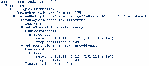
procedures.The audio and video streams are transported using an unreliable protocol, while data communications are transported using a reliable protocol.The transport address that the receiving endpoint has assigned to a specific logical channel (audio, video or data) is transported by the OPENLOGICALCHANNELACK message (an example is given in Figure 2.7).That transport address is used to transmit the information stream associated with that logical channel.
Figure 2.7 OPENLOGICALCHANNELACK message content
2.2.1.5.4. Call services
When the call is active, the terminal may request additional call services. Among the services reported here are the Bandwidth Change Services and Supplementary Services.With Bandwidth Change Services. During a conference, the endpoints or gatekeeper (if involved) may, at any time, P.25
[IP Telephony Cookbook] / Technological Background
request an increase or decrease in the call bandwidth. If the aggregate bit rate of all transmitted and received channels does not exceed the current call bandwidth, then an endpoint may change the bit rate of a logical channel without requesting a bandwidth change. After requesting a bandwidth change, the endpoint waits for confirmation prior to actually changing the bit rate (confirmation usually comes from the gatekeeper). Asking for call bandwidth changes is performed using a BANDWIDTH CHANGE REQUEST(BRQ) message. If the request is not accepted, a BANDWIDTH CHANGE REJECT (BRJ) message is returned to the endpoint. If the request is accepted, a BANDWIDTH CHANGE CONFIRM (BCF) is sent back to the endpoint.With Supplementary Services, support is optional.The H.450 Series of Recommendations describes a method of providing Supplementary Services in the H.323
environment. Figure 2.8 reports some of the supplementary services defined so far and their number in the series.
Recommendation number
Recommendation Title
H.450.1
Supplementary Service Framework
H.450.2
Call Transfer Supplementary Service
H.450.3
Call Diversion Supplementary Service
H.450.4
Call Hold Supplementary Service
H.450.5
Call Park and Pickup Supplementary Service
H.450.6
Call Waiting Supplementary Service
H.450.7
Message Waiting Supplementary Service
H.450.8
Name Identification Supplementary Service
H.450.9
Call Completion Supplementary Service
H.450.10
Call Offer Supplementary Service
H.450.11
Call Intrusion Supplementary Service
Figure 2.8 Supplementary services of the H.450-Series
2.2.1.5.5. Call termination
A call may be terminated either by both endpoints or by the gatekeeper. Call termination is defined using the following procedure:
- video should be terminated after a complete picture and then all logical channels for video closed;
- data transmission should be terminated and then all logical channels for data closed;
- audio transmission should be terminated and then all logical channels for audio closed;
- the H.245 ENDSESSIONCOMMAND message (H.245 Control Channel) should be sent by the endpoint/gatekeeper.This message indicates that the call has to be disconnected; then the H.245 message transmission should be terminated;
- the ENDSESSIONCOMMAND message should be sent back to the sending endpoint and then the H.245 Control Channel should be closed;
- a RELEASE COMPLETE message should be sent closing the Call Signalling Channel if this is still open.
An endpoint receiving an ENDSESSIONCOMMAND message does not need to receive it back again after replying to it in order to clear a call.Terminating a call within a conference does not mean that the whole conference needs to be terminated. In order to terminate a conference, an H.245 message (DROPCONFERENCE) is used.Then the MC should terminate the calls with the endpoint as described above.
P.26
[IP Telephony Cookbook] / Technological Background
A call may be terminated differently depending on the gatekeeper presence and on the party issuing the call termination:
- call clearing without a gatekeeper
No further action is required;
- call clearing with a gatekeeper
The gatekeeper needs to be informed about the call termination. After RELEASE
COMPLE