This chapter introduces the user to the concept of setting up advanced services.There are sections for configuration and basic operations of gatewaying functions (Section 5.1) (gateways configuration, SIP to H.323 and vice-versa, H.323 to PSTN and SIP to PSTN), supplementary services (Section 5.2) and multipoint conferencing (Section 5.3).
-/ 5.1 Gatewaying
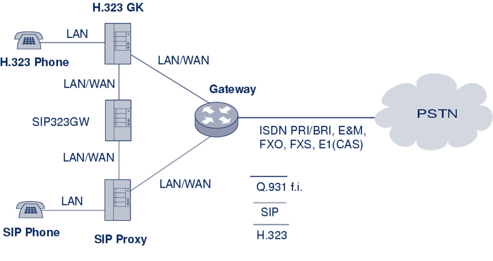
Please refer to Section 4.1 for a general architecture of SIP-H.323 and PSTN gatewaying.This section deals with an analysis of the characteristics of gateways and the configuration principles for the gatewaying functions to be set up in an advanced environment.The topics detailed in this section range from VoIP - PSTN gateways to SIP - H.323 Gateways configuration, ending with short considerations on accounting.
-/ 5.1.1 Gateway interfaces
One of the most important interfaces in IP Telephony is between a PBX and a voice gateway (VoGW). It enables communication between PBX phones and IP phones (H.323 or SIP) and can also facilitate communication to PSTN see (Figure 5.1).When a PBX phone dials a number which is not another PBX extension, the PBX can forward to the voice gateway either calls to numbers beginning with a specified prefix (so called access prefix that the users dials before the required number to get to IP Telephony network) or all calls. Similarly, a voice gateway can forward to the PBX, calls to PBX phones.When a PBX phone dials a number in a PSTN, the PBX can forward the call directly to the PSTN (e.g., over ISDN) or it can forward the call to a voice gateway, which forwards it to a selected PSTN operator over the Internet.
There are different kinds of PBX to voice gateway interfaces with different features and costs.
Your choice of the interface-type will probably depend on which features you require: acceptable cost, availability and whether there is already some interface present in the PBX and the voice gateway. In this section, some technical details are provided on different kinds of PBX-to-voice gateway interfaces. Signalling systems are also described briefly, such as Channel Associated Signalling (CAS), E&M signalling methods, Q-signalling and the Q.931 call control protocol and examples are given of exchanged messages during correct communication.
-/ 5.1.1.1 Subscriber Loop
A subscriber loop, also called a U-interface, is a 2-wire interface used primarily when connecting a telephone set to a Subscriber Line Module Analogue (SLMA). SLMA is the name of the P.135
[IP Telephony Cookbook] / Setting Up Advanced Services
analogue module in a PBX. A corresponding module in a voice gateway is called a Foreign Exchange Station (FXS).
Figure 5.1 Voice gateway interfaces - PBX role
FXS and SLMA modules can also be interconnected to trunk modules.Trunk Module Analogue (TMA) is the name of the trunk module on the PBX side, and Foreign Exchange Office (FXO) is the common name of the corresponding module in a voice gateway.
A subscriber loop can be used in any of the following configurations:
- Telephone to SLMA or FXS;
- FXS to TMA;
- FXO to SLMA.
There are two operating modes:
- FXO/TMA - telephone emulation (as common terminal equipment).This is a very simple mode. It only detects a ringing signal and provides digit dialling and switching between off-hook (to close the loop) an on-hook (to open the loop);
- FXS/SLMA - subscriber line circuit emulation. In this mode, the SLMA or FXS waits for a closed loop that will generate a current flow and a signalling tone of 425 Hz (with 10%
tolerance).The Subscriber Line Interface Circuit Emulation (SLIC) provides the functions of BORSHT (Battery, Overvoltage, Ringing, Supervision, Hybrid 2/4 wires and Testing).
The two most common methods for end-loop signalling are loop-start and ground-start signalling. DTMF (Dual Tone Multi-Frequency) is commonly used to transmit telephone number digits. DTMF tones identify numbers 0 through 9 and the * and # symbols. Digits are represented by a particular combination of two frequencies from the high group and the low group. Each group includes only four frequencies. Out of sixteen possible combinations, twelve are used on the keypad. DDI (Direct Dialling In) is possible only through a DTMF suffix, that is, during the connection time when the calling party normally is already paying for the connection.
P.136
[IP Telephony Cookbook] / Setting Up Advanced Services
-/ 5.1.1.2 E&M interfaces
E&M is commonly explained as both ‘Ear and Mouth’ and ‘recEive and transMit’. E&M interfaces allow DDI without restrictions before the conversation starts.There are several different types of E&M interfaces according to signalling and number of interconnecting wires.Type V (see Figure 5.2) is very popular in Europe. In the commonly used 6-wire interconnection, the individual wires are used as follows:
- one pair of wires (wires E and M) is used for signalling;
- one pair of wires is used for the outgoing voice path;
- one pair of wires is used for the incoming voice path.
This 6-wire connection can be reduced into 4-wires:
- one pair of wires (wires E and M) is used for signalling;
- one pair of wires is used for the voice path in both directions (which can cause a problem with echo cancellation and inhibits a possibility to use an amplifier).
-48 V
-48 V
E-lead
E-lead
with detector
E
E