Figure 5.3 ISDN configuration
U interface is a two-wire interface from the telephone exchange; it supports full-duplex data transfer over a single pair of wires: only a single device can be connected to a U interface.
T interface is between network terminations NT1 and NT2: NT1 converts two-wire U interface into four-wire T interface.
P.138
[IP Telephony Cookbook] / Setting Up Advanced Services
S interface and T interface are electrically equivalent. ISDN devices include an NT-2 in their design.The NT2 communicates with terminal equipment TE1 (ISDN terminal) or TE2 (non-ISDN, connected to NT2 via terminal adapter), and handles the layer 2 and layer 3 ISDN
protocols.
Network Termination NT is divided into NT1 and NT2; NT1 works in Layer 1 and NT2 in Layers 2 and 3. NT1 and NT2 are connected by a four-wire T interface.
Terminal Equipment TE1 is an ISDN compatible device (TE1 is connected to NT2 via a four-wire S interface).
Terminal Equipment TE2 is a non-ISDN-compatible device that requires terminal adapter interconnection.
Terminal Adapter provides an ISDN-compliant interface to NT and a standard interface to TE2
(such as RS-232, USB, X.21, etc.).
Because a PBX can provide NT2 functions, the T interface is commonly used for interconnection of a PBX and a Voice Gateway.The PBX works in the user-side operation mode and the Voice Gateway in the network-side operation mode.
5.1.1.4.1 Q.931
The L2 and L3 interface of ISDN is also referred to as the Digital Subscriber Signalling System No.1 (DSS1).The L2 protocol of ISDN is ITU Q.920/Q. 921 and the L3 protocol is ITU
Q.930/Q.931. Q.932 enables general procedures for accessing and controlling supplementary services.
Q.931 provides call control capabilities. Some of the most important Q.931 messages are:
- Setup;
- Setup acknowledge;
- Call proceeding;
- Progress;
- Alerting;
- Connect;
- Connect acknowledge;
- Disconnect;
- Release complete;
- Information.
The destination digits can be sent in two forms during call-setup:
- complete called party number in the SETUP message, also known as the en-bloc signal;
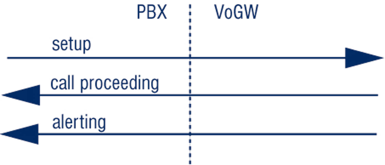
- one by one in separate messages, also known as the overlap signal An example of Q.931 Call control messages in call-setup with the en-bloc signal is shown in Figure 5.4.This example corresponds to the following setup:
- Cisco AS5300 was used as a Voice Gateway and debugging was enabled with ‘debug isdn q931’
command;
P.139
[IP Telephony Cookbook] / Setting Up Advanced Services
- The call was initiated from the Technical University in Ostrava to the Czech Technical University in Prague,.The PBX was connected through ISDN/PRI and the called number was sent as the en-bloc in the SETUP message;
- The Calling Party Number was 596991699
- The Called Party Number was 224352979
Figure 5.4 Q.931 call control messages in call-setup with the en-bloc signal Jun 24 18:30:12.817: ISDN Se0:15: RX <- SETUP pd = 8 callref = 0x0002
Sending Complete
Bearer Capability i = 0x8090A3
Channel ID i = 0xA9838E
Calling Party Number i = 0x00, 0x83, '596991699', Plan:Unknown, ...
Called Party Number i = 0x80, '224352979', Plan:Unknown, Type:U...
High Layer Compat i = 0x9181
Jun 24 18:30:12.837: ISDN Se0:15: TX -> CALL_PROC pd = 8 callref = 0x8002
Channel ID i = 0xA9838E
Jun 24 18:30:13.129: ISDN Se0:15: TX -> ALERTING pd = 8 callref = 0x8002
Progress Ind i = 0x8188 - In-band info or appropriate now available Progress Ind i = 0x8182 - Destination address is non-ISDN
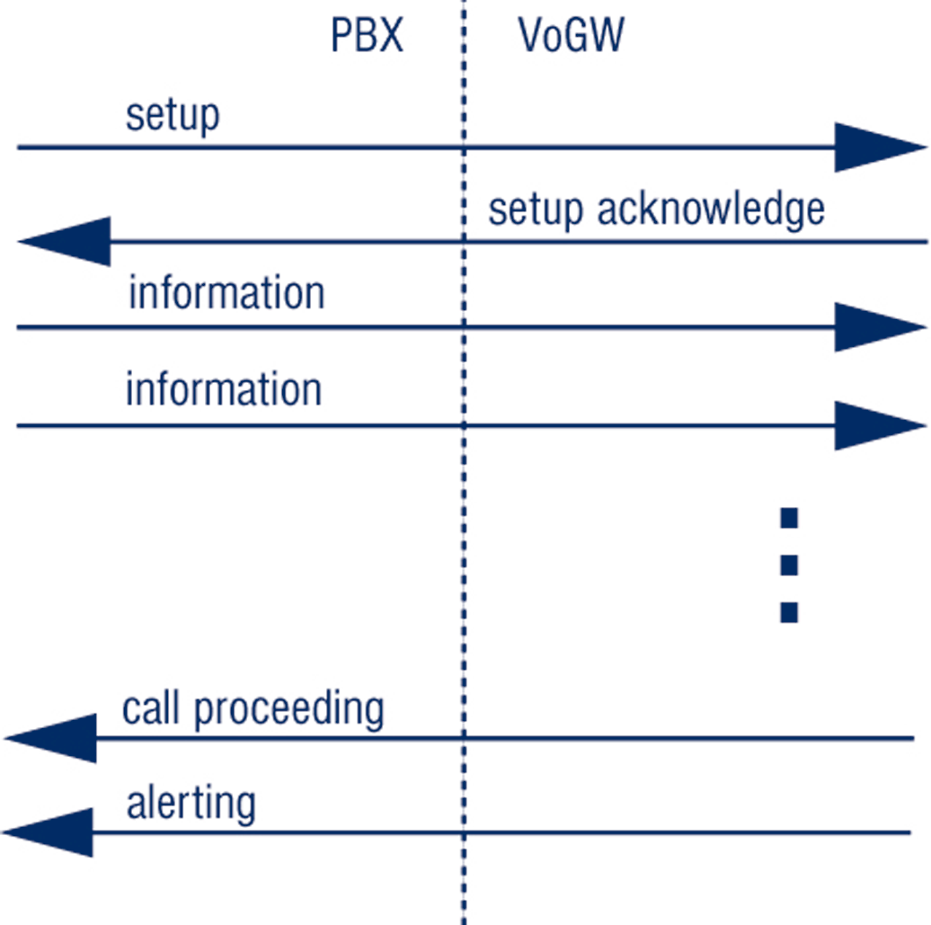
An example of Q.931 call control messages in call-setup with the overlap signal is shown in Figure 5.5.
Figure 5.5 Q.931 call control messages in call-setup with overlap
P.140
[IP Telephony Cookbook] / Setting Up Advanced Services
This example corresponds to the following setup:
- Cisco AS5300 was used as a Voice Gateway; debugging was enabled with a debug isdn q931
command;
- The call was initiated from the Czech Technical University in Prague to PSTN (Public Switched Telephone Network); the PBX in Prague was connected through ISDN/PRI and the called number was sent as the digit by digit (overlap) in the SETUP and INFOMATION messages;
- The Calling Party Number is 224355406;
- The Called Party Number is 224324997.
Jun 24 18:31:43.092: ISDN Se1:15: RX <- SETUP pd = 8 callref = 0x540A Bearer Capability i = 0x8090A3
Channel ID i = 0xA1838E
Progress Ind i = 0x8183 - Origination address is non-ISDN
Calling Party Number i = 0x31, 0x81, '224355406', Plan:ISDN, Type:.
Called Party Number i = 0x81, '2', Plan:ISDN, Type:Unknown
Jun 24 18:31:43.104: ISDN Se1:15: TX -> SETUP_ACK pd = 8 callref = 0xD40A Channel ID i = 0xA9838E
Jun 24 18:31:43.808: ISDN Se1:15: RX <- INFORMATION pd = 8 callref = 0x540A Called Party Number i = 0x81, '2', Plan:ISDN, Type:Unknown
Jun 24 18:31:45.152: ISDN Se1:15: RX <- INFORMATION pd = 8 callref = 0x540A Called Party Number i = 0x81, '4', Plan:ISDN, Type:Unknown
Jun 24 18:31:46.536: ISDN Se1:15: RX <- INFORMATION pd = 8 callref = 0x540A Called Party Number i = 0x81, '3', Plan:ISDN, Type:Unknown
Jun 24 18:31:47.564: ISDN Se1:15: RX <- INFORMATION pd = 8 callref = 0x540A Called Party Number i = 0x81, '2', Plan:ISDN, Type:Unknown
Jun 24 18:31:48.896: ISDN Se1:15: RX <- INFORMATION pd = 8 callref = 0x540A Called Party Number i = 0x81, '4', Plan:ISDN, Type:Unknown
Jun 24 18:31:51.012: ISDN Se1:15: RX <- INFORMATION pd = 8 callref = 0x540A Called Party Number i = 0x81, '9', Plan:ISDN, Type:Unknown
Jun 24 18:31:52.696: ISDN Se1:15: RX <- INFORMATION pd = 8 callref = 0x540A Called Party Number i = 0x81, '9', Plan:ISDN, Type:Unknown
Jun 24 18:31:54.480: ISDN Se1:15: RX <- INFORMATION pd = 8 callref = 0x540A Called Party Number i = 0x81, '7', Plan:ISDN, Type:Unknown
Jun 24 18:31:54.604: ISDN Se1:15: TX -> CALL_PROC pd = 8 callref = 0xD40A Jun 24 18:31:55.684: ISDN Se1:15: TX -> ALERTING pd = 8 callref = 0xD40A Progress Ind i = 0x8288 - In-band info or appropriate now available
-/ 5.1.2 Gatewaying from H.323 to PSTN/ISDN
One of the most useful H.323 services is the ability of VoIP calling parties (H.323 world) to reach the PSTN (classic telephony world).This service is provided by H.323/PSTN gateways and the functionality they provide is:
- forwarding of incoming calls from the PSTN and call signalling to H.323;
- termination of incoming calls from H.323 and forwarding to the PSTN;
- accounting for calls utilising the gateway;
- optional support for H.320 (ISDN)-capable conferencing endpoints.
P.141
[IP Telephony Cookbook] / Setting Up Advanced Services
This section introduces the basic principles on how to perform gatewaying using H.323. Basic configuration guidelines and operational principles of commercial and open source gatekeepers are described here in order to detail how to set up gatekeepers for interconnection with PSTN.
Moreover, details on the configuration of gateways are given in order to provide guidelines on how to configure gateways to be part of an H.323 network.
-/ 5.1.2.1 Using a RADVISION OnLAN 323 L2W-323 Gateway
The RADVISION OnLAN 323 L2W-323 Gateway is a hardware-based H.323 to H.320 gateway, which allows H.323 endpoints to reach destinations on the PSTN or specialised H.320 (ISDN-based) endpoints and vice versa.The L2W-323, in its most common configuration, has four Ethernet (LAN) interfaces and two ISDN BRI (WAN) interfaces. It is designed for stand-alone use and thus integrates the functions of a gatekeeper, as well as a gateway, under the same hood. It is presently not available for sale but it has quite a large installed base, considering that the Cisco 3520 is essentially the same product marketed by Cisco.
5.1.2.1.1 Installation
Its installation is straight-forward, requiring merely power, a network interface, BRI ISDN
interfaces and a PC on the same LAN for setting-up initial configuration parameters through a windows-based application.To manage the device, install the RADVISION OnLAN Tools from the installation disks, by running the setup.exe program on the PC. Since the gateway has no network configuration to begin with, the PC running the software will have to be on the same LAN in order to perform initial network setup of the unit. After specifying an IP address for the Ethernet interface of the unit, the configuration application can then be run remotely.
5.1.2.1.2 Configuration
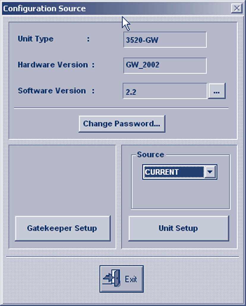
When running the configuration application, you will need to specify the IP address of the target device, or choose one from the list of detected devices on the same LAN. After entering the administrative password, you are presented with a window where you specify which configuration to edit.The options are to edit the currently-loaded configuration of the device, or a previously saved-to-file configuration.The next step is to select which functionality to configure: the gatekeeper (select Gatekeeper Setup) or the gateway (select Unit Setup).
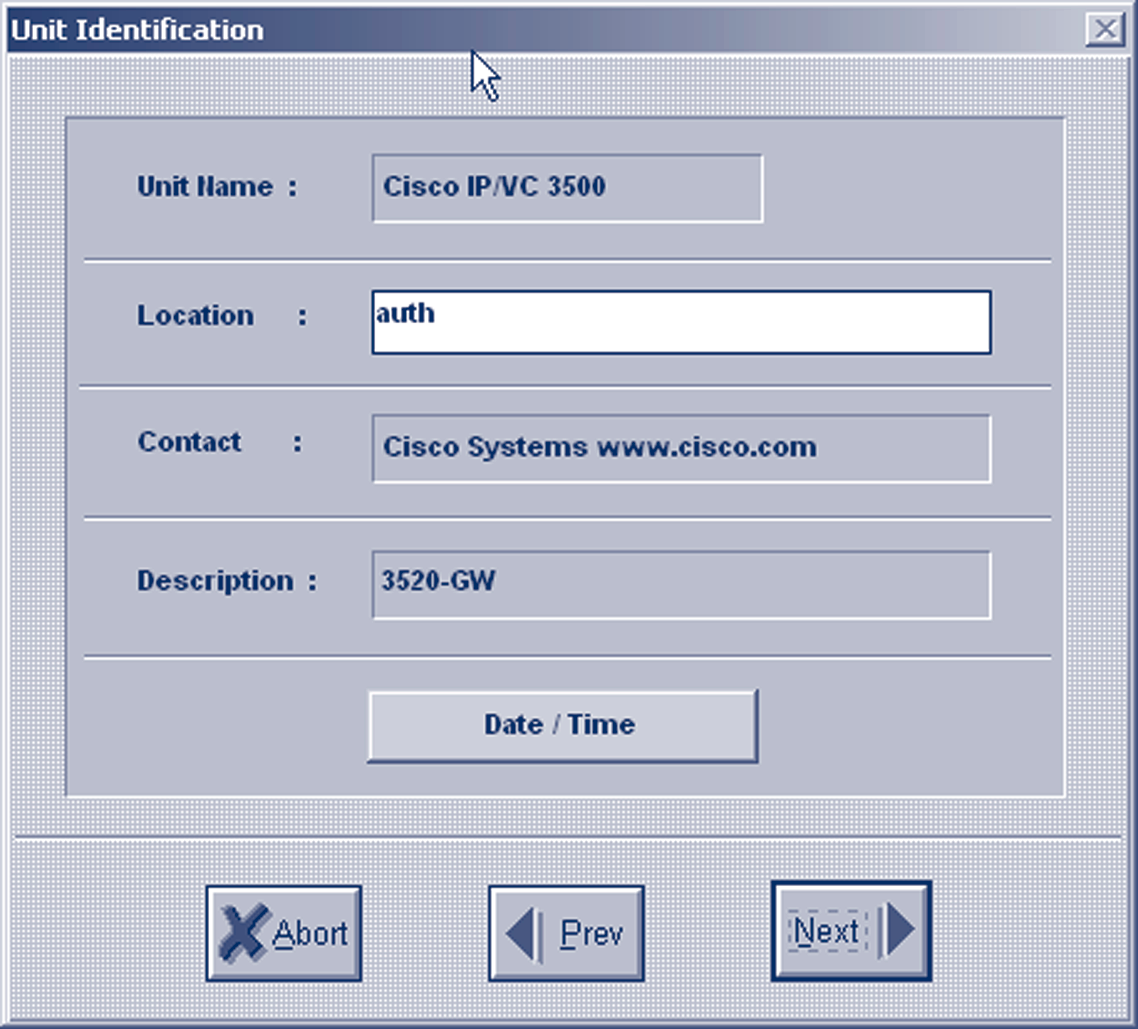
Only the second option is of interest, since the gateway can register with any of the gatekeepers detailed above, and the built-in gatekeeper can be turned off since it provides only basic functionality. Select Unit Setup and proceed with Unit Identification and Date/Time options, which are informational only, by pressing the Next button.
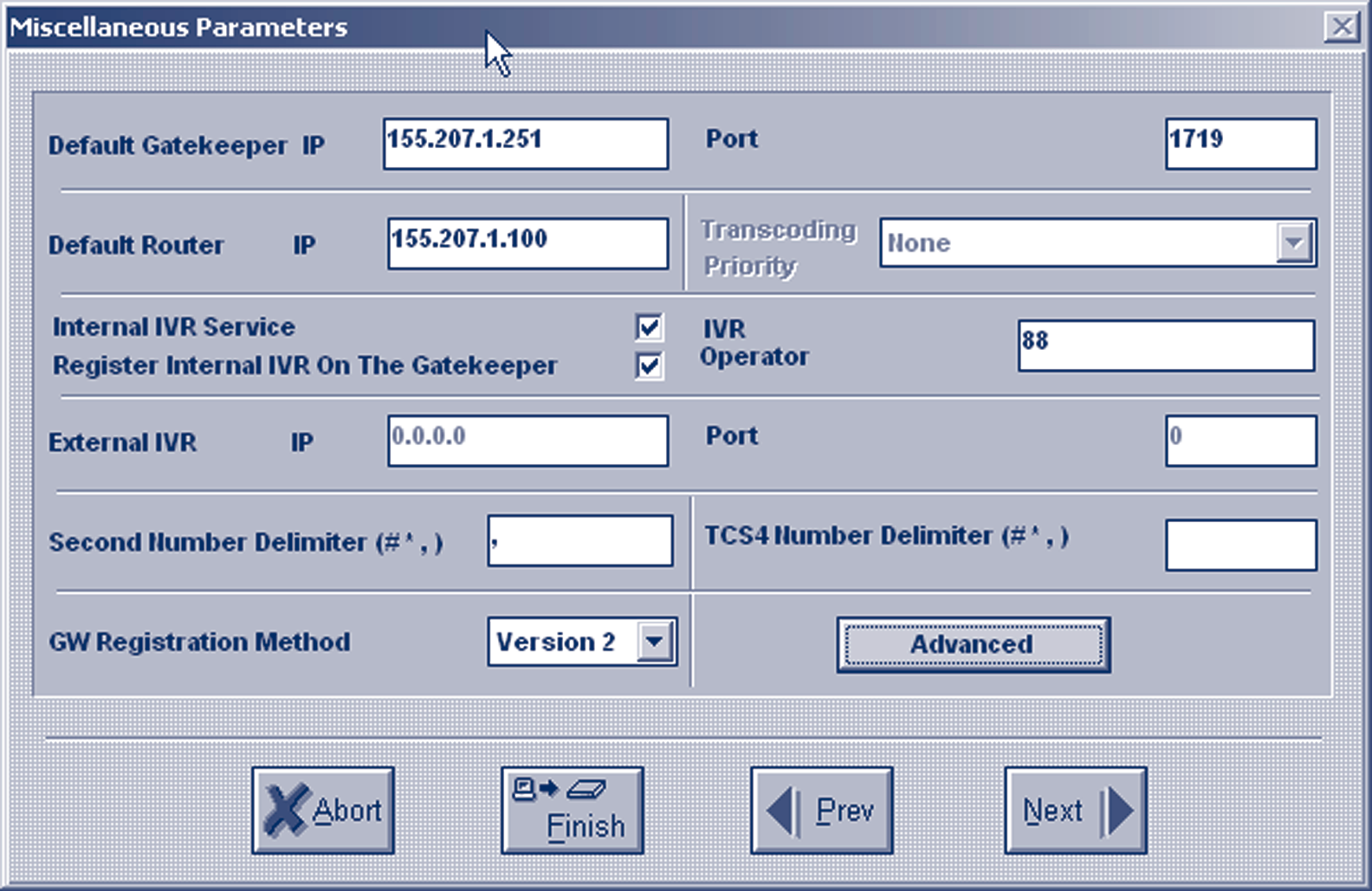
The next screen, Miscellaneous Parameters, presents a number of configuration options.The critical settings are the ones for Default Gatekeeper and for Default Router IP, which you must set to the IP address of the gatekeeper controlling your zone, and the IP address of the router (network gateway in the IP protocol sense).The rest of the settings can be left at their default state.
P.142
[IP Telephony Cookbook] / Setting Up Advanced Services
Figure 5.6 OnLAN configuration entry
Figure 5.7 OnLAN unit identification
The next screen, LAN Port Settings, is responsible for configuring the Ethernet interfaces.There are four screens, one for each of the four Ethernet ports. Configuring just one interface with an IP
Address and IP Mask is sufficient. A summary screen with settings for all four ports follows.
P.143
[IP Telephony Cookbook] / Setting Up Advanced Services
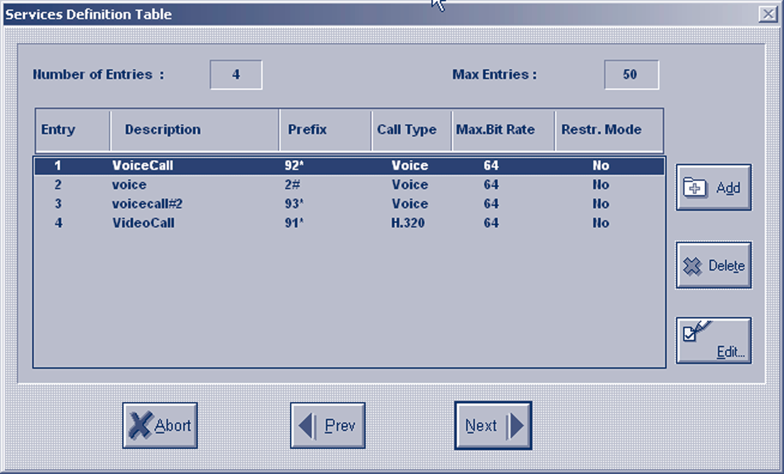
Figure 5.8 OnLAN miscellaneous parameters and gateway registration on gatekeeper The next screen, Services Definition Table, is the most important one, since it defines the services that the gateway will make available to calling parties, by registering them with its controlling gatekeeper.
Figure 5.9 OnLAN-defined gateway services
P.144
[IP Telephony Cookbook] / Setting Up Advanced Services
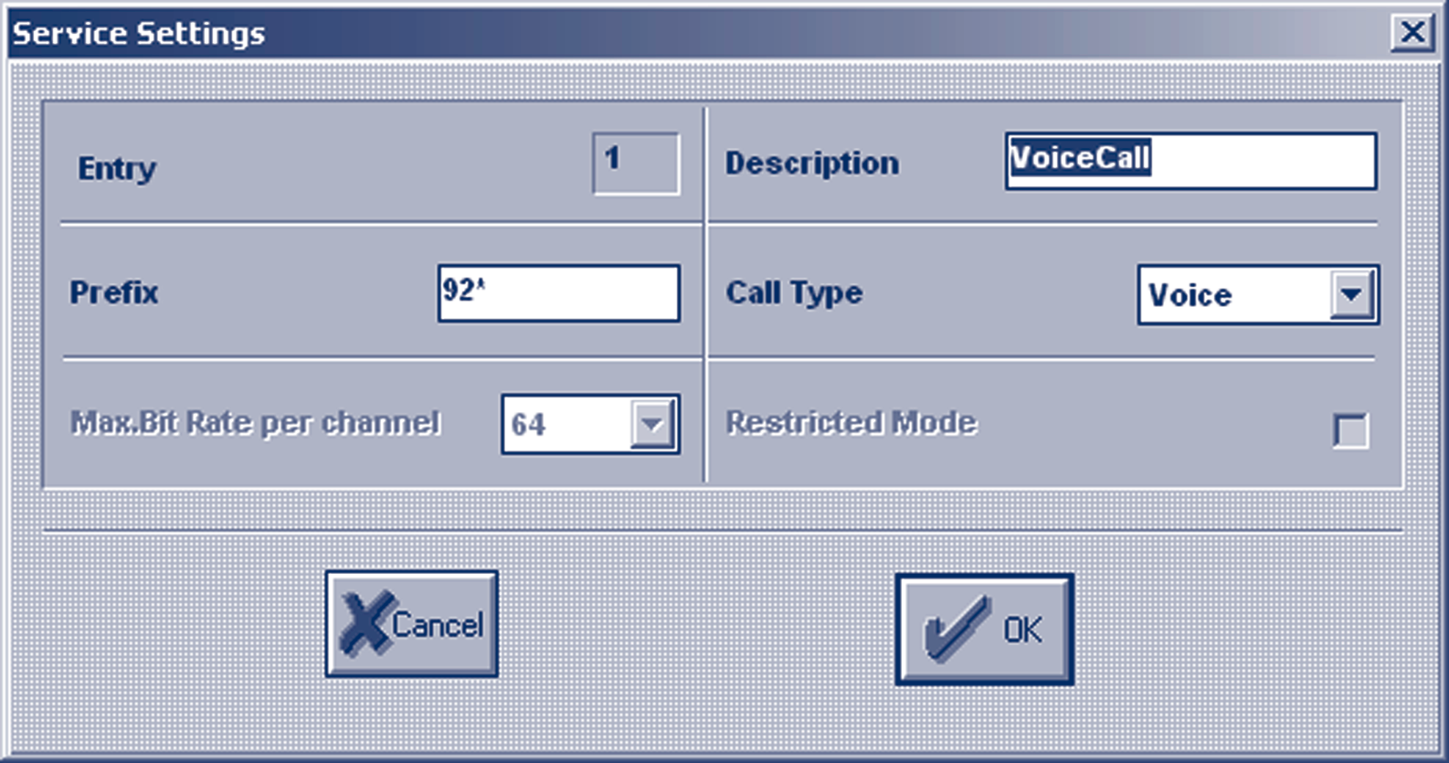
Each service definition includes information about the Prefix. It is called with the Call Type, which can be voice-only or H.320 (voice and video), and the Maximum Bit Rate which a call of this type and will be required. By defining different services, the calling parties are given the option to choose the type of call they can make, based on the service prefix they dial, assuming the prefixes are well known to the users, or at least that the gatekeepers have pre-selected default gateway services. For example, if the gateway defines a voice-only service with a prefix of e.g., 9, the administrator of the gatekeeper will likely make this the default service to route all calls to the gateway. Any user requiring a voice and video call will have to know the service prefix, e.g., 8, for that special type of call.The L2W gateway will already have template services defined, but you can add, edit or delete services as needed.There is certainly one thing you will need to customise and that is the service prefixes, in order to make them match your local dialling scheme.
Figure 5.10 OnLAN editing of a service definition
The next screens refer to WAN Port Settings which, for an ISDN interface, present relative settings.The country-specific ISDN protocol must be selected, and the Phone Number connected to the ISDN port can be indicated. Also, specific services can be enabled or disabled for this WAN port, assuming more than one type of WAN port is available, each with distinct capabilities. A summary screen with settings for all WAN ports follows.
At the end of the configuration wizard, you are given the option to save the new configuration settings in a file before downloading them to the gateway itself. At this point, the gateway is reloaded and the new settings are applied.
5.1.2.1.3 Operation
Immediately after configuration and reload, the gateway attempts to register its services with the gatekeeper.This must be verified on the gatekeeper-side before attempting to use the gateway's services. Specifically, there are two things that must be checked: a) the registration of the gateway on the gatekeeper and b) the registration of its service prefixes on the gatekeeper. For example, on the Cisco MCM Gatekeeper, the appropriate commands would be:
> show gatekeeper endpoints
GATEKEEPER ENDPOINT REGISTRATION
================================
CallSignalAddr Port RASSignalAddr Port Zone Name Type Flags P.145[IP Telephony Cookbook] / Setting Up Advanced Services
194.257.8.150 1820 194.257.8.150 1024 gk.mydomain.org CH320-GW
H323-ID: GW4134522623
At least one entry should refer to the registration of the gateway, indicating its IP address, the type of registration (H320-GW) and the H.323 alias of the unit (GW4134522623).
> show gatekeeper gw-type-prefixes
GATEWAY TYPE PREFIX TABLE
=========================
Prefix: 92*Zone gk.mydomain.org master gateway list:
194.257.8.150:1820 GW4134522623
Prefix: 93*
Zone gk.mydomain.org master gateway list:
194.257.8.150:1820 GW4134522623
A listing of all registered services at the gatekeeper should include an entry for each of the services defined on the gateway, indicating the prefix, and the IP address and the H.323 alias of the gateway to forward calls to. If registration of services with the gatekeeper is confirmed, the gateway is ready to service calls, which can be traced through the gatekeeper tools.
The gateway can be monitored by a command-line interface only:
> telnet 194.257.8.150
Trying 194.257.8.150...
Connected to 194.257.8.150.
Escape character is '^]'.
VxWorks login: admin
Password:
->
At this prompt, no command can be entered to explicit logs, but passive monitoring of events is provided. Logs on this interface can be overwhelming, but the L2W gateway does not provide any other means of debugging, or monitoring. Please note that in the current release a bug makes the L2W gateway unregister from the gatekeeper after some time, making its services unavailable to the zone. Check often for registration of gateway services and in case they are lost, reboot the gateway to force gatekeeper registration again.The most flexible way to reboot the gateway is to use the telnet interface, login, and apply a Control-X command.
5.1.2.1.4 Authentication
In environments where gatekeeper registration is authenticated, the gateway has to provide authentication credentials in order for the gatekeeper to allow its registration. If H.235
authentication is required by the gatekeeper, the L2W gateway does not support it and administrative measures must be taken at the gatekeeper-side to exempt it from authentication. If authentication by H.323 alias and password is required, e.g., for the Cisco MCM piggy-back mechanism, the L2W gateway has a fixed H.323 alias that it tries to register with the gatekeeper P.146
[IP Telephony Cookbook] / Setting Up Advanced Services
(of the format GWnnnnnnnnnn, where n is a number generated by the gateway itself and is not configurable).The administrator must make sure that this specific H.323 alias is allowed to register on the gatekeeper with no password. Similar measures must be taken in case an IP-address plus H.323 alias-authentication method is applied on the gatekeeper-side.
-/ 5.1.2.2 Gatewaying H.323 using Cisco
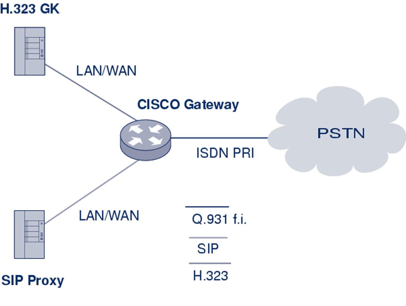
In this subsection, an example of how a Cisco Voice Gateway should be configured for interconnection with a PBX is presented. See Figure 5.11 for an illustration of the interconnection.The same procedure could be used for interconnecting a Cisco Voice Gateway with PSTN/ISDN
Figure 5.11 Cisco voice gateway interconnection
Gateway configuration can be divided into three main parts:
- Protocol configuration;
- Interface configuration;
- Dial-peer configuration.
The example corresponds to the following setup. As a Voice Gateway is used, Cisco 2651XM with appropriate IOS is connected through PRI/ISDN to the PBX and is registered to a gatekeeper.
Examples of the configuration were cut off from the Cisco CLI command and show running-config output and comments.
5.1.2.2.1 Protocol configuration
Gatekeeper peering and gateway id are set up in this section.The Cisco gateway could serve as a voice gateway for both H.323 and SIP protocols at the same time, but the SIP protocol-specific part is configured in a completely different configuration section of the gateway (not the sip-gateway, see Section 5.2.2). Use of the h323-gateway command is recommended, set in a loopback interface configuration section. Use of a loopback IP address in registration and P.147
[IP Telephony Cookbook] / Setting Up Advanced Services
accounting messages helps to manage the system easily if the gateway has more than one interface used for VoIP.
h323-gateway voip interface
h323-gateway voip id GK1-CESNET2 ipaddr 195.113.113.131 1718 priority 100
h323-gateway voip id GK2-CESNET2 ipaddr 195.113.144.85 1718
h323-gateway voip h323-id VoGW-ZCU
h323-gateway voip tech-prefix 1#
Voice gateway is registered to gatekeeper GK1-CESNET2
A second gatekeeper GK2-CESNET2 is used as backup
The h323-id of the Voice Gateway is VoGW-ZCU. It is checked on the gatekeeper and is needed for successful registration
5.1.2.2.2 Interface configuration
Interconnection to a PBX or a PSTN also has to be properly set up at interface level (router(config-if)#).Telephony interface configuration is independent on the used VoIP
signalling protocol. In this section, there are configured ISDN parameters for signalling the channel (the sixteenth channel has number 15 by Cisco).
interface Serial0/0:15
isdn switch-type primary-net5
isdn overlap-receiving T302 5000
isdn protocol-emulate network
isdn send-alerting
isdn sending-complete
isdn outgoing-voice info-transfer-capability 3.1kHz-audio
primary-net5 is the setting of the DSS1 (EuroISDN) signalling protocol on the primary interface PRI (basic-net3 is used on the BRI).
timer T302 is the interval in milliseconds for overlap mode (the interface waits 5 seconds for possible additional call-control information).
isdn protocol-emulate network is the configuration of the Layer2 and Layer3 of the ISDN
protocol, the Voice Gateway is working as NT and the PBX is in the slave mode.
isdn send-alerting causes the Alerting message to be is sent out before the Connect message.
isdn sending-complete is an optional enhancement, where the sending complete information element is required in the outgoing call setup message.The last command specifies the transfer capability for voice calls.
5.1.2.2.3 Dial-peer configuration
The next configuration step is setting up the call rules.This is done by a dial-peer command set from the basic config mode (router(config)#) of the Cisco gateway. If the gateway should provide calls from both sides (to and from the PSTN/PBX), a set of at least two dial-peers has to be configured.
P.148
[IP Telephony Cookbook] / Setting Up Advanced Services
dial-peer voice 1 pots
destination-pattern 42037763....
progress_ind alert enable 8
direct-inward-dial
port 0/0:15
These commands specify rules for calls to the PSTN(PBX) from the VoIP-side.
The called number prefix is 42037763 and must be followed with four digits of extension (four dots substitution pattern).The best match to destination pattern chooses the right dial peer.
progress_ind alert enable 8 is the transcription of the Progress element in the Alerting message.This transcription causes B-channels to interconnect and allows the resolving of a possible problem with the ring-back tone.
The rules are written into the port interface 0/0:15 with DDI (Direct Dialling In).
dial-peer voice 112 voip
destination-pattern 420.........
session target ras
no vad
These commands specify rules for calls leading to the VoIP-side from the PSTN(PBX):
- The called number prefix is 420 and it must be followed with nine digits;
- The target of this session is the gatekeeper, accessible through RAS signalling;
- The last command specifies that the Voice Activity Detection is not possible (higher voice quality);
- The default configuration is VAD with CNG function (Comfort Noise Generation).
The user is reminded here that the listed configuration may not be sufficient to run a voice gateway on Cisco routers. Commands may depend on the type of the router and the IOS version used.
-/ 5.1.2.3 Gatewaying H.323 using a GNU Gatekeeper
How to set up services using GNU Gatekeeper was already described in Section 4.5.3. Here, enhanced configuration and operation for GnuGK to be used with a gateway in order to reach people who are using ordinary telephones is described.
The gatekeeper has to know which calls are supposed to be routed over the gateway and what numbers shall be called directly. Using the [RasSrv::GWPrefixes] section of the config file, the administrator tells the gatekeeper the prefix of numbers that will be routed over the gateway.
[RasSrv::GWPrefixes]
gw-PSTN=0
gw-MOBILE=3
These entries tell the gatekeeper to route all calls to E.164 numbers, starting with 0, to the gateway that has registered with the H.323 alias gw-PSTN, and all calls to the E.164 numbers, P.149
[IP Telephony Cookbook] / Setting Up Advanced Services
starting with 3, to the gateway that has registered with the H.323 alias gw-MOBILE. If there is no registered gateway with these alias’, the call will fail. Note that you must use the gateway alias.
You cannot just tell the gatekeeper the IP number of the gateway. Static configuration of gateway-ip-address/prefix is, in principle, possible using the [RasSrv::PermanentEndpoints]
configuration section, but such a solution is not advised, because it leads to errors when a network reconfiguration is done.
When using a gateway, you often have to use different numbers internally and rewrite them before sending them over a gateway into the telephone network.You can use the RasSrv::RewriteE164 section to configure this.
[RasSrv::RewriteE164]
12345=08765
In this example, the gatekeeper is configured to replace the numbers 12345 at the beginning of the E.164 number dialled to 08765 (for example, 12345-99 is rewritten to 08765-99). Please refer to rewrite for the section syntax.
A gateway can register its prefixes with the gatekeeper by containing supportedPrefixes in the terminalType field of RRQ.The following option defines whether to accept the specified prefixes of a gateway.
AcceptGatewayPrefixes=1
#Default: 1
5.1.3. Gatewaying from SIP to PSTN/ISDN
-/ 5.1.3.1 Gatewaying SIP using Cisco
Configuration of a SIP gateway is almost same as the configuration of an H.323 Gateway and because configuration of an H.323 Gateway is already described in Section 5.1.2.2, the same settings are not described again here (for an interface configuration which is exactly the same).
Only configuration specific to SIP is described. Readers should read Section 5.1.2.2 first.
Dial-peer configuration is almost same as described in Section 5.1.2.2.The only difference is that ras is replaced by sip-server. For example,
dial-peer voice 112 voip
destination-pattern 420.........
session target sip-server
no vad
P.150
[IP Telephony Cookbook] / Setting Up Advanced Services
-/ 5.1.3.2 sip-ua configuration
All the SIP parameters are configured in the sip-ua section. An example configuration might look like:
sip-ua
nat symmetric role passive
nat symmetric check-media-src
retry invite 4
retry response 3
retry bye 2
retry cancel 2
sip-server dns:iptel.org
The first parameters configure the gateway to be passive.That is good for the Connection Oriented Media.Value. Passive means that if there is a direction=active parameter in SDP, then the gateway will wait with the sending of media until it