Scenegraph node reference
5.3 Bounds and CollisionBounds
It is time to look at usage examples and implementation hints and tips for the most commonly used scenegraph elements available in Java 3D. This chapter is intended to supplement the Sun Java 3D API documentation. Whether you are browsing or reading the book chapter by chapter, you may want to skim the detailed implementation advice and move ahead.
The Java 3D system supports the concept of a “compiled” scenegraph. Compilation is typically carried out after the scenegraph structure has been built, but before it is displayed. During compilation Java 3D analyzes the elements in the scenegraph, as well as the scenegraph structure, and attempts to perform optimizations to improve rendering time and scenegraph traversal.
Java 3D uses the capability bits that have been set on the scenegraph elements to identify which optimizations can be applied to the scenegraph. The capability bits that have been set for an object defines a contract between you (the application developer) and the Java 3D system. If, for example, you have not set the ALLOW_TRANSFORM_WRITE capability on a TransformGroup, the Java 3D system could use the fact that the 4 × 4 transformation matrix within the TransformGroup remains constant to optimize rendering.
The use of capability bits is a powerful mechanism for adding complex optimizations in future versions of Java 3D. At present two main scenegraph optimizations have been implemented: attribute merging/sorting and geometry merging.
To take advantage of the benefits of compilation, you must override some of the default settings of the Shape3D-derived objects in your scenegraph. In particular, the pickable property is set by default for Shape3D objects; objects with the pickable property will not be optimized during the compile process.
5.1.1 Appearance merging and sorting
The Appearances assigned to Shape3D objects in the scenegraph are computationally quite expensive for the scenegraph renderer. They take up memory, and when the renderer hits an Appearance, it must make a long and complex series of OpenGL or DirectX calls to the rendering subsystem to add the information within the Appearance to the rendering pipeline. Two optimizations can take place: duplicate Appearance objects can be removed and replaced with a reference to a unique Appearance object, and Shape3D objects can be rendered in an order such that changes in Appearance state are minimized. These optimizations reduce memory consumption and save on calls to the rendering subsystem. Obviously, only Appearance objects that do not have any WRITE capability bits set can be optimized using scenegraph compilation.
5.1.2 Geometry merging
Geometry merging attempts to minimize the number of discrete Shape3D objects in the scenegraph. A scenegraph will benefit from geometry merging if the Shape3D objects fulfill the following criteria:
The compilation process will sort and attempt to merge the static subgraphs in the scenegraph. Dynamic subgraphs, that is, Nodes with writable attributes (such as Group.ALLOW_CHILDREN_WRITE), will have their static child Nodes processed while ignoring the dynamic child Nodes.
java.lang.Object
|
+--javax.media.j3d.SceneGraphObject
|
+--javax.media.j3d.Node
Node is an abstract base class for Group and Leaf Nodes. It defines methods to control bounding volumes (through the Bounds class), automatic computation of Bounds, collision detection and picking (mouse selection). Most important, it allows each Node to have a single parent Node. The parent Node allows arbitrarily complex scenegraph structures to be defined.
Group-derived Nodes have the ability to manage a Collection of Node-derived child objects, while Leaf-derived Nodes define the leaves of the scenegraph tree. In other words, Leaf Nodes cannot have child Nodes.
5.3 Bounds and CollisionBounds
Java 3D maintains object boundary information for the Nodes in the scenegraph. Every Node in the scenegraph contains a Bounds field that stores the geometric extent of the Node. Java 3D uses the Node Bounds information extensively, for everything from visibility testing to Behavior scheduling.
In addition, Shape3D- and Group-derived objects in the scenegraph (i.e., all geometric objects and geometric container objects) contain the CollisionBounds field. The Java 3D collision detection engine makes use of the CollisionBounds field. A simplistic (and hence poor) collision detection algorithm would iterate through the objects in the scenegraph and test for an intersection between the CollisionBounds for a Shape3D object and the CollisionBounds of every other Shape3D object in the scenegraph.
There are three classes derived from Bounds: BoundingBox, BoundingSphere, and BoundingPolytope. BoundingBox defines a cuboidal volume of space; BoundingSphere, a spherical volume of space; and BoundingPolytope, a set of intersecting planes that define a closed, convex volume.
Node-derived classes also have the option to autocompute their Bounds. This option is enabled by default and allows geometric objects in the scenegraph, as well as their parents, to compute the Bounds field based upon the positions of the geometric primitives (points, lines) from which they are composed.
Consult the following code snippets for the effects of creating an object with various combinations of Bounds and/or CollisionBounds.
From BoundsTest.java
//use the defaults
ColorCube cube0 = new ColorCube( 1.0 );
RESULTS
BoundsAutoCompute: true
Collidable: true
Pickable: true
Bounds: Bounding box: Lower=–1.0 –1.0 –1.0 Upper=1.0 1.0 1.0
CollisionBounds: null
By default, Shape3D objects are created as Collidable and Pickable, and they autocompute their Bounds. No CollisionBounds are assigned, so if collision detection functionality is required, the collision mode USE_GEOMETRY should be used.
//explicitly set the Bounds using a BoundingBox
ColorCube cube1 = new ColorCube( 2.0 );
cube1.setBoundsAutoCompute( false );
Bounds bounds = new BoundingBox( new Point3d( –2, –2, –2),
new Point3d( 2, 2, 2 ) );
cube1.setBounds( bounds );
cube1.setCollisionBounds( bounds );
RESULTS
BoundsAutoCompute: false
Collidable: true
Pickable: true
Bounds: Bounding box: Lower = –2.0 –2.0 –2.0 Upper = 2.0 2.0 2.0
CollisionBounds: Bounding box: Lower = –2.0 –2.0 –2.0 Upper = 2.0 2.0 2.0
By calling setBoundsAutoCompute( false ), the Bounds and CollisionBounds for the Shape3D object can be manually specified, as one would expect.
//explicitly set the Bounds using a BoundingSphere
ColorCube cube2 = new ColorCube( 4.0 ); cube2.setBoundsAutoCompute( false );
bounds = new BoundingSphere( new Point3d( 0, 0, 0 ), 4 );
cube2.setBounds( bounds );
cube2.setCollisionBounds( bounds );
RESULTS
BoundsAutoCompute: false
Collidable: true
Pickable: true
Bounds: Bounding box: Lower = –4.0 –4.0 –4.0 Upper = 4.0 4.0 4.0
CollisionBounds: Center = (0.0, 0.0, 0.0) Radius = 4.0
Surprisingly, if a BoundingSphere is used to specify the Bounds and CollisionBounds for the Shape3D object, the BoundingSphere will be internally converted to a BoundingBox and used for the Bounds. The CollisionBounds uses the original BoundingSphere, however.
//auto compute, manual collision
ColorCube cube3 = new ColorCube( 6.0 );
cube3.setBoundsAutoCompute( true );
bounds = new BoundingBox( new Point3d( –10, –10, –10 ),
new Point3d( 10, 10, 10 ) );
cube3.setCollisionBounds( bounds );
RESULTS
BoundsAutoCompute: true
Collidable: true
Pickable: true
Bounds: Bounding box: Lower = –6.0 –6.0 –6.0 Upper = 6.0 6.0 6.0
CollisionBounds: Bounding box: Lower = –10.0 –10.0 –10.0 Upper = 10.0 10.0 10.0
//auto compute both
ColorCube cube4 = new ColorCube( 6.0 );
cube4.setBoundsAutoCompute( true );
RESULTS
BoundsAutoCompute: true
Collidable: true
Pickable: true
Bounds: Bounding box: Lower = –6.0 –6.0 –6.0 Upper = 6.0 6.0 6.0
CollisionBounds: null
5.3.1 Bounds and CollisionBounds propagation
There is a final piece to the Bounds story. The scenegraph is a hierarchical data structure, so it makes sense for the Bounds of a parent object to automatically encompass a volume large enough to hold all of its child objects. Java 3D can perform these calculations automatically, as table 5.1 illustrates (from BoundsTest.java).
Table 5.1 Bounds propagation within a branch of the scenegraph
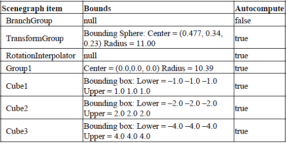
Group1 contains the five ColorCubes, as created earlier in the section. The largest ColorCube has a BoundingBox of (–6,–6,–6) –> (6,6,6). The radius of the smallest BoundingSphere to enclose the largest ColorCube is therefore radius = sqrt( 62 + 62 + 62) = 10.392. This BoundingSphere is automatically created by Java 3D and assigned to the parent Group (Group1) of the ColorCubes. Note that Group1 has the property setBoundsAutoCompute( true ).
Group2 contains a Shape3D object composed from 200 random points in a PointArray (positioned between –5 and 5 in the x-, y-, and z-axes). Java 3D automatically creates a BoundingBox to enclose the points composing the Shape3D object—approximately: (–5,–5,–5) –> (5,5,5). The BoundingBox is automatically assigned to the Shape3D object containing the PointArray. The Bounds for the Shape3D object are propagated up the scenegraph hierarchy as a BoundingSphere and assigned to Group2. The center of the BoundingSphere is positioned to minimize the radius (in this case approximately 0,0,0). The radius of the BoundingSphere is approximately computed from radius = sqrt( 52 + 52 + 52) = 8.660.
The parent of Group1, Group2, and RotationInterpolator is TransformGroup. TransformGroup combines the Bounds objects for its children to compute its own Bounds. In this case, as the Bounds of the children are all approximately centered at (0,0,0), which is equal to the Bounds of Group1 (which is the largest).
NOTE
The top-level parent BranchGroup node has the attribute setBoundsAutoCompute( false ).
//routine to create a Shape3D object made from a point cloud
//of 200 random points
protected Group createPoints()
{
Group group = new Group();
final int kNumPoints = 200;
final double kRadius = 10.0;
Point3d points[] = new Point3d[kNumPoints];
for( int n = 0; n <kNumPoints; n++ )
{
double randX = (java.lang.Math.random() * kRadius ) – kRadius/2;
double randY = (java.lang.Math.random() * kRadius ) – kRadius/2;
double randZ = (java.lang.Math.random() * kRadius ) – kRadius/2;
points[n] = new Point3d( randX, randY, randZ );
}
PointArray pointArray = new PointArray( points.length,
GeometryArray.COLOR_4 | GeometryArray.COORDINATES );
pointArray.setCoordinates( 0, points );
Shape3D shapePoints =
new Shape3D( pointArray, new Appearance() );
group.addChild( shapePoints );
return group;
}
Note that the propagation of Bounds up the scenegraph hierarchy (from child to parent) does not occur with CollisionBounds. Cube4 has CollisionBounds of (–10,–10,–10) –> (10,10,10) but these do not influence the Bounds of the parent Group1. Surprisingly, the CollisionBounds of Cube4 do not influence the CollisionBounds of the parent Group1 either. It appears that the application programmer is responsible for manually propagating CollisionBounds from child to parent Nodes.
java.lang.Object
|
+--javax.media.j3d.SceneGraphObject
|
+--javax.media.j3d.Node
|
+--javax.media.j3d.Group
Group defines a scenegraph Node that contains a collection of child Nodes. It defines the following child Node management methods:
void addChild(Node child)
java.util.Enumeration getAllChildren()
Node getChild(int index)
void insertChild(Node child, int index)
void moveTo(BranchGroup branchGroup)
int numChildren()
void removeChild(int index)
void setChild(Node child, int index)
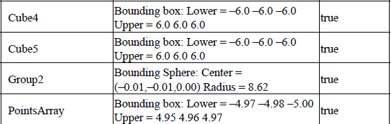
These methods essentially delegate, in obvious ways, to the internal collection that manages the child Nodes within the Group.Table 5.2 shows the capabilities defined by Group.
Table 5.2 Capabilities defined by Group
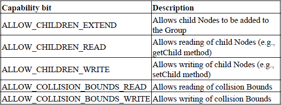
Group is an important base class for the Java 3D Node management classes, and it can also be instantiated in its own right. For increased flexibility, however, I recommend BranchGroup Nodes because they can be dynamically added or removed from the scenegraph. The classes derived from Group are shown in table 5.3.
Table 5.3 Classes derived from Group

Note that an instance of any of the Group-derived classes, including SharedGroup, can only be added to a single location within the scenegraph. Attempting to add a scenegraph node to a scenegraph that already has an assigned parent (i.e., a node that has already been added to the scenegraph) will result in a run-time exception. I discuss reusing scenegraph branches using a SharedGroup and a Link later in this chapter.
5.4.1 Remove a child Node by reference
It is useful to be able to remove a child Node from its parent Group without knowing the child Node’s index. Unfortunately, because scenegraph Nodes are removed from a Group using void removeChild(int index), there is no easy way to remove a Shape3D object from a Group if you do not know the index at which it was originally inserted. In the following example, I remove a Shape3D object that corresponds to the internal, application-specific data structure. By storing the application-specific data structure in the UserData field of the Shape3D, I can retrieve the index of the Shape3D and remove it from its parent Group object.
ClassificationObject is an application-specific data structure that is stored in each child Node to identify it. To store the ClassificationObject in the Node, use node.setUserData( classificationObject );
public void removeChildObject( ClassificationObject targetObj )
{
//we need to remove the object by index, so we have to iterate
//through our objects to find it.
//get an enumeration containing all the child nodes
Enumeration enum = getAllChildren();
int nIndex = 0;
Node obj = null;
//scan through the child nodes until we find the one that
//corresponds to our data structure.
while( enum.hasMoreElements() != false )
{
obj = (Node) enum.nextElement();
if( targetObj != obj.getUserData() )
nIndex++;
else
break;
}
//if we found the object, we can now remove it by index.
if( nIndex <numChildren() )
removeChild( nIndex );
else
System.out.println( "Failed to find child object during remove operation." );
}
Note that in the preceding example, the implicit this is an instance of a class derived from Group that has the capability to remove child Nodes based on an internal data structure.
java.lang.Object
|
+--javax.media.j3d.SceneGraphObject
|
+--javax.media.j3d.Node
|
+--javax.media.j3d.Group
|
+--javax.media.j3d.Switch
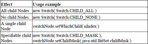
The Switch Node provides the facility to define a Group Node that can conditionally display or hide its child Nodes (see table 5.4).
Table 5.4 Switch Node modes
For example, to create a Switch Node that displays child Nodes at index 3, 6, and 7 use the following:
From SwitchTest.java
//create the Switch Node
Switch switchGroup = new Switch( Switch.CHILD_MASK );
switchGroup.setCapability( Switch.ALLOW_SWITCH_WRITE );
switchGroup.addChild( createLabel( "Child Node 1", labelScale ) );
switchGroup.addChild( createLabel( "Child Node 2", labelScale ) );
switchGroup.addChild( createLabel( "Child Node 3", labelScale ) );
switchGroup.addChild( createLabel( "Child Node 4", labelScale ) );
switchGroup.addChild( createLabel( "Child Node 5", labelScale ) );
switchGroup.addChild( createLabel( "Child Node 6", labelScale ) );
switchGroup.addChild( createLabel( "Child Node 7", labelScale ) );
//create the logical mask to control Node visibility java.util.BitSet visibleNodes = new java.util.BitSet( switchGroup.numChildren() );
//make the third, sixth and seventh nodes visible visibleNodes.set( 2 );
visibleNodes.set( 5 );
visibleNodes.set( 6 );
//assign the visibility mask to the Switch switchGroup.setChildMask( visibleNodes );
The output of the SwitchTest example is shown in figure 5.1.
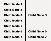
Figure 5.1 The effect of using a BitSet mask and a Switch Node. On the left, the Switch Node has been created with the Switch.CHILD_ALL attribute. On the right, a BitSet has been created to display the third, sixth, and seventh Node through a call to setChildMask. The child elements being controlled by the Switch Node are Text2D objects
The Switch Node can be used to implement modal static scenegraphs, that is, scenegraphs that are essentially of a fixed structure but which the user can influence through adding or removing prebuilt sections.
Switch Nodes can also be used to implement simple animation using the SwitchInterpolator Behavior (figure 5.2). The SwitchInterpolator attaches to a Switch Node and cycles the active child of the Switch Node using an Alpha object. For example, a simple 3D “flip-book” style animation could be achieved by adding several versions of a 3D model to a Switch Node and triggering a