Figures 3.4 and 3.5 illustrate the idea behind the consistent hashing approach. In figure 3.4 there are three red colored nodes A, B and C and four blue colored objects 1–4 that are mapped to a hash-function’s result range which is imagined and pictured as a ring. Which object is mapped to which node is determined by moving clockwise around the ring. So, objects 4 and 1 are mapped to node A, object 2 to node B and object 3 to node C. When a node leaves the system, cache objects will get mapped to their adjacent node (in clockwise direction) and when a node enters the system it will get hashed onto the ring and will overtake objects. An example is depicted in figure 3.5 where compared to figure 3.4 node C left and node D entered the system, so that now objects 3 and 4 will get mapped to node D. This shows that by changing the number of nodes not all objects have to be remapped to the new set of nodes but only part of the objects.
In this raw form there are still issues with this procedure: at first, the distribution of nodes on the ring is actually random as their positions are determined by a hash function and the intervals between nodes may
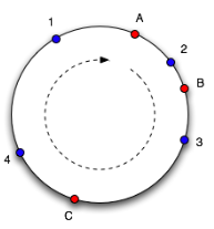
Figure 3.4.: Consistent Hashing – Initial Situation (taken from [Whi07])
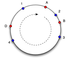
Figure 3.5.: Consistent Hashing – Situation after Node Joining and Departure (taken from [Whi07])
be “unbalanced” which in turn results in an unbalanced distribution of cache objects on these nodes (as it can already be seen in the small scenario of figure 3.5 where node D has to take cache objects from a greater interval than node A and especially node B). An approach to solve this issue is to hash a number of representatives/replicas—also called virtual nodes—for each physical node onto the ring (cf. [Whi07], as an example see figure 3.6). The number of virtual nodes for a physical can be defined individually according to its hardware capacity (cpu, memory, disk capacity) and does not have to be the same for all physical nodes. By appending e.g. a replica counter to a node’s id which then gets hashed, these virtual nodes should distribute points for this node all over the ring.
In his blog post on consistent hashing Tom White has simulated the effect of adding virtual nodes in a setting where he distributes 10,000 objects across ten physical nodes. As a result, the standard deviation of the objects distribution can be dropped from 100% without virtual nodes to 50% with only 2–5 virtual nodes and to 5–10% with 500 virtual nodes per physical node (cf. [Whi07]).
When applied to persistent storages, further issues arise: if a node has left the scene, data stored on this node becomes unavailable, unless it has been replicated to other nodes before; in the opposite case of a new node joining the others, adjacent nodes are no longer responsible for some pieces of data which they still store but not get asked for anymore as the corresponding objects are no longer hashed to them by requesting clients. In order to address this issue, a replication factor (r) can be introduced. By doing so, not only the next node but the next r (physical!) nodes in clockwise direction become responsible for an object (cf. [K+10b], [Ho09a]). Figure 3.7 depicts such a scenario with replicated data: the uppercase letters again represent storage nodes that are–according to the idea of virtual nodes–mapped multiple times onto
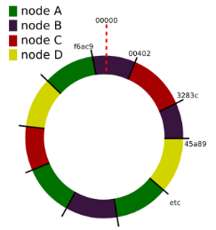
Figure 3.6.: Consistent Hashing – Virtual Nodes Example (taken from [Lip09, slide 12])
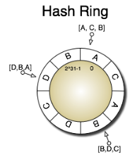
Figure 3.7.: Consistent Hashing – Example with Virtual Nodes and Replicated Data (taken from [K+10b])
the ring, and