3.1 User Interface Design
So far there have been three types of interface: 1) command-line 2) menu 3) GUI (graphical user interface) which tell the users what they would want the computer interface to do.
In the early days of computing, the only mode of human computer interaction was command-line interface. Communication was driven by commands or responses to system-generated queries. For example, you can instruct the command-line interface to delete a file by using the following command:
del c:\file1.txt
The command-line is further developed to form a menu. For example, a menu can contain the following choice of commands:
To delete the file, press key D To display the file, press key L To open a file, press key O
To save the file, press key S
Menu-driven systems have advantages over command-line interface. For instance,
1) Users don’t have to know or remember commands
2) User errors are avoided
3) Syntax errors are prevented.
As hardware became more sophisticated and software engineers became more familiar with human factors and their impact on interface design, the modern window oriented pick and point interface evolved resulting in GUI or WIMP (windows, icons, menus and pointing devices). Such an interface presents the user with a set of controls or widgets such as buttons, scroll bars and text boxes. Instead of typing an option, the user makes a selection using a mouse button.
The advantages of GUI include:
1) They are relatively easy to learn and use.
2) The user can use multiple windows for interacting with the system
3) Fast full-screen interaction is possible
4) Different types of information can be displayed simultaneously, enabling the user to switch contexts
5) The use of graphical icons, pull-down menus, buttons and scrolling techniques reduce the amount of typing
Theo Mandel in his book on Interface Design defined three golden rules:
1) Place the user in control
2) Reduce the user’s memory load
3) Make the interface consistent
As a designer you may be allured to using constraints and limitations on your interface design which makes it easy to develop but difficult to use. Mandel defines a number of design principles that help the user to maintain control. These are:
1) Define interaction modes in such a way that does not force a user to take undesired actions.
2) Provide for flexible interactions: Because different users prefer to interact in different ways, choices should be provided.
3) Allow user interaction to be uninterruptible and undoable: Even when the user is involved in a series of interactions, he should be able to interrupt and do something else without losing any of his work and also have the option of “undo”.
4) Allow the skilled user to customize interaction: Skilled users may often find that they have to use the same set of interactions repeatedly. It then becomes necessary on the part of the skilled user to use a “macro mechanism” to customize the interface for fast interaction.
5) Hide technical details from the novice user: The novice user should never be aware of the internals inside the machine while interacting with the interface, such as, operating system or file management functions and others.
6) Design for direct interaction with objects on the screen: The user feels a sense of control when they are able to manipulate objects to do tasks as if they were physical things.
A well-designed interface doesn’t require the user to remember a lot because then he would become more error-prone while interacting with the system. Mandel defines design principles that enable an interface to reduce the user’s memory load:
Reduce demand on short-term memory: When users are involved in complex tasks, the demand on short-term memory can be huge. The interface should be designed in such a way to reduce the memory load to remember past actions, inputs, and results. Visual cues in this case might help without having to recall.
Establish meaningful defaults: The average user should be able to make sense out of original default settings. However, he should also be able to re-specify his own preferences for default values.
Define shortcuts that are intuitive: When shortcuts are defined for functional operations, they should be tied to the action that is easy to remember.
The visual layout of the interface should be based on a real world perspective: For example, a bill payment system should use a checkbook and check register based on real world visual cues so that it is easy for the user to understand rather than memorize.
The interface should be organized hierarchically: That is, information about a task, an object, or some behavior should be presented first at the highest level of abstraction. More detail should be presented after the user indicates interest with a mouse click on a particular level.
The interface should present and acquire information in a consistent manner. Mandel defined the following principles for making a consistent interface:
1) Many interfaces present complex layers of interaction with many screen images. Window titles, graphical icons and color coding should enable the user to recognize the context of work at hand. He should know which task he was working and transition to newer tasks smoothly.
2) Maintain consistency across a group of applications. A set of applications (or products) should all implement the same design rules so that consistency is maintained for all interaction.
3) If past interactive models have met user expectations, do not make changes unless there is a definite reason to do so. Once a particular interactive sequence has become a particular standard, the user expects this in every application he uses.
The various users of an effective interface system can be categorized as follows:
With reference to interface system design, understanding the problem means understanding:
In order to bring in line the system’s mental image and design model of the user, the software engineer has to understand the users themselves and how they will use the system. For this to happen we need to collect information from a wide spectrum of resources. Some of these are:
In order to carry out task analysis, we are presented with some questions:
To answer these questions, use the techniques discussed in sections 1.2, 1.4, 1.5, 2.2, 2.3, 2.4, 2.5 and previous subsections in 3.1 earlier in the book.
Modularity has to do with the structure of software. It is the end product of several design methods such as, functional decomposition, object-oriented design, data structure design and others. It can be considered as the sum total of several subsystems or components that are as separate as possible from each other. This is the foundation of modularity.
The guidelines described later in this section should be able to answer questions as follows:
A component results from any current or future mechanism where software is divided into manageable portions. In various programming languages, a component is a method, class or package. But in this chapter, we will relate component to manageable portions.
Components can be categorized as follows:
A computation-only component has no data between subsequent calls. A math method can be an example.
A memory component is an assembly of durable data. Durable data are those that be stored as backup in disks for example, a database or file system.
A manager data can be an abstract data type such as a stack or queue and their operations.
A controller component can initiate other components and manage interaction among them.
A link component transfers information from one component to another. User interface and network software are examples.
What should be the size of a component? It can be constructed in one of the following ways:
With small components, each one of them has very few lines of code so that the complexity of each is significantly low. On the other hand, complexity in this structure arises from the innumerable number of small components.
However with large components, the structure is simple in the number of components which is only a few but within each component, the complexity is high due to the vast number of lines of code.
So which structure is preferable? Actually both. For a piece of software, large components are needed during design and maintenance while small components during debugging. The less complex a component is, the easier it is to understand it and therefore the smaller size of the component helps. While one component is being studied, we do need to keep track of what other components might be doing. This is where a level of abstraction is useful in the structure of software so that while we study other components about what they do, we do not need to understand how they do it. So we can focus only on one component at a time, other components being separate. After examining one component, we can take our attention to the next. So what is actually important here is the size and complexity of the components and their interactions.
Why should we keep a program simple? Here are a few solutions:
How does a good engineer maintain complete control and understanding over all the components of the project? The answer is by adhering to the simplicity of each component, keeping the few lines of code within them simple. There may be several arguments on this approach but this is really the solution everything boils down to.
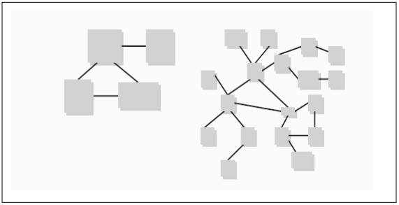
Fig 3.1 : Alternative Software Structures
Within a component, data can be local or global. Keeping data global means all components within a piece of software access these data so that when we need to understand or examine a component, other components depending on the same data will have to be studied. This means separation of components or modularity is not rightly achieved.
On the other hand, if data is local for instance, within a method (which is, in fact a component), those data will be accessed by those components only. So in this case, a high degree of separation or modularity is achieved. However, these local data can be passed around the program as parameters.
In general, local data is preferable because:
Summing up, in a software structure, the amount of global data should be minimized while that for local data should be maximized.
Information hiding or encapsulation helps to structure software, giving it a great modular design. Considering a data structure or file structure, its structure itself and the statements that access or modify the structure are all part of a single component. A piece of data encapsulated like this cannot be accessed directly but only via one of the methods associated with the data. Such a collection of data and methods is called a class or object in object-oriented programming.
Information hiding can be utilized by using a stack concept. Methods push item onto the stack top and pop items from the stack top. Given this illustration, the stack implementer can make use of an array, linked list etc. while coding. However, the user of the stack does not need to know how the stack is implemented.
Information hiding meets three criteria:
When the design of a file structure for instance, is needed to be modified, as few components as possible are taken into consideration and ultimately modified. Preferably as much as possible, only one component will just be changed.
When the system is developed by a team of programmers, care should be taken that the interfaces among the components are as simple as possible. Information hiding actually asserts that interfaces are actually calls on methods which are definitely simpler than accesses to shared data or file structures.
For design, checking, testing and maintenance, we need to study the components as independently as possible. Information hiding makes this possible while shared or global data will not.
Alternative ways of describing interactions among components and within components are coupling and cohesion. A piece of software should ideally be developed from its components such that there is minimum interaction among components (low coupling) and a high degree of interaction within each component (high cohesion).
Coupling and cohesion are opposite sides of the same coin. Strong cohesion results in weak coupling and vice versa.
Architectural-based design consists of the structure of data and program components required to build a computer-based system and the interrelationships among the architectural components.
A software engineer can design both the data and architecture but often a huge, complex system has to be built so that the work of data is given to a specialist such as, a database or data warehouse designer while the architecture is handled by the system architect based on the software requirements derived from requirements engineering analysis.
The steps in the architectural design include data design and proceeds with the derivations of one or more alternatives of the structure of architectural system. Once an alternative is selected, the architecture is extended with an architectural design method. The work product of this system is the development of data architecture and program structure along with component properties and the interactions among them.
To make sure the work product is done right, at each stage, the software design work product is tested for clarity, correctness, completeness and consistency along with requirements among each other.
An architectural description is a set of work products that portray the different views of the system. In order to understand this description, look at the following example:
The architect of an office building must work with various stakeholders. The owner of the building (one stakeholder) holds the view that it should be elegant looking and have enough space and infrastructure to ensure profits. Accordingly, the architect must meet the demands of this stakeholder’s view. The architect does this by drawing three-dimensional views of the big picture of the office building and also, two-dimensional views of floor plans covering space and infrastructure.
Another stakeholder could be a steel structural fabricator who will provide steel for the skeleton structure of the building. Among the many details he would require, he needs architectural information regarding the steel that will support the building, their dimensions, connectivity, materials and many more. Each of these concerns is realized by a different work product that outlines a different view of the architecture. One such view, for instance, is for the steel skeleton structure of the architecture.
An architectural description of a software-based system is similar to that illustrated in the office building example above.
A widely used way of presenting, sharing and reusing knowledge about software systems is the idea of patterns. Here I give several examples of architectural patterns.
This pattern organizes the system into layers. Each layer has a related functionality. Each of them provides service to the layer above it. Therefore, the lowest layers are likely to provide chore services, which will be widely used throughout the system.
This system is used:
i) When there is a need to add layers on top of the existing system.
ii) When the development is involved among several teams, each team working on a layer of functionality.
iii) When there is the need for multi-level security.
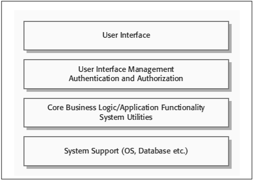
Fig 3.2: A Layered Architectural Pattern
All the system components get access to all the data in the system that is stored in a central repository. These components cannot interact directly but only through the repository.
The following figure shows an example of IDE (Integrated Development Environment- a software application that provides comprehensive facilities to computer programmers for software development) where components use a repository of software tools. Each tool generates information, which can then be used by other tools.
This system pattern is preferable when large volumes of data are generated and have to be stored for lengthy durations.
Components are independent – one component doesn’t need to know the existence of other components. A change initiated in one component can be propagated to all other components. A fault in one component affects other components of the system. Distributing the repository across several computers may be difficult.
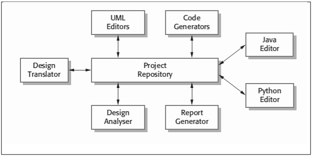
Fig: 3.3: A repository architecture for an IDE
In a client-server architecture, each separate server delivers service to a group of clients which make use of them.
This architecture is used when the data in a shared database has to be accessed in a variety of locations.
Servers are distributed across a network while a general functionality for instance, a printing service can be available to all clients without being implemented by all services. Performance can be unpredictable because of dependence on the network as well as system.
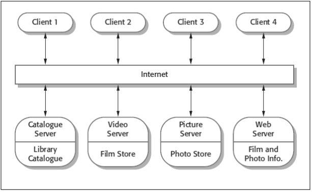
Fig 3.4: A client-server architecture for a film library
Each processing component in the system acts as a filter and carries out a single type of data transformation while data flows from one component to another as in a pipe.
This system is commonly used in data processing applications based on both batch and transaction-based processing.
The system can be executed as a sequential and concurrent system.
Each transformation must parse its input and un-parse its output to the compatible form.
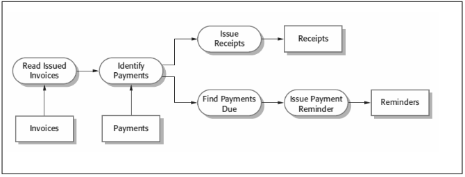
Fig 3.5: An example of Pipe and Filter architecture
Application systems usually meet a business or organization need. There are many types of application systems and sometimes they differ from each other too much. Many of these applications although dissimilar have much in common and yet can be represented by a single abstract application architecture. This can be shown by the following two types of architecture:
1. Transaction processing applications: They are database-centered applications that process user requests for information and update the information in a database. This class of system includes interactive banking systems, e-commerce systems, information systems, and booking systems.
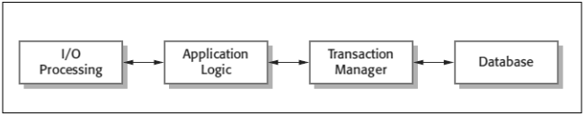
Fig 3.6: An example of transaction processing application systems
2. Language Processing Systems : The best-known language processing systems are compilers, which translate high-level language programs into machine code. However, language processing systems are also used to interpret command languages for databases and information systems, and markup languages such as XML.
This type of design creates a new application by providing a set of proven solutions to a clearly outlined set of problems.
The software engineer examines each problem and encounters the probable solution by consulting one or more patterns repositories.
Reinventing the wheel occurs all the time in software development but it’s a waste of time and energy. You can provide a known solution to a specific problem by examining existing design patterns. This helps to move closer to the completion of the design faster and adeptly. The problem space is subdivided into specific problems associated with software functions and features. Problems can also be organized by type: architectural, component-level, algorithmic, user interface, etc.
A design pattern can be visualized as a three-part objective among a certain context, a problem and a solution. For software design, the reader should be able to understand the environment where the problem resides and look for an appropriate solution for that problem. A system of forces such as constraints and limitations influence how the problem can be interpreted and how an effective solution can be applied.
An effective design pattern is found in the following way: