The Unified Modeling Language (UML) is a graphical notation for describing object oriented software. It is not a method for design but a notation that can help with designing software or help to document software after it is complete.
This appendix only shows a part of the diagrams which belongs to a larger and more complex UML notation. We illustrate a little of the following diagrams here:
These diagrams describe, in outline, the use cases associated with a system. Figure B.1 shows an example of a use case diagram for users of a bank ATM. In this diagram, there is a single type of user, a bank customer. A customer can ask the system to carry out either of the two functions: withdraw cash or check balance.
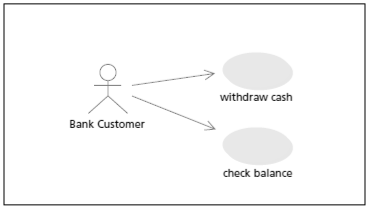
Fig. B.1: A Use Case Diagram
These diagrams describe classes and their interrelationships. Classes are shown as rectangles containing the class name. The simplest relationship is where a class uses another. For example, in figure B.2, class Game uses the classes Defender, Alien, Laser and Bomb. This means the Game creates objects from these classes and calls methods in the objects created from these classes.
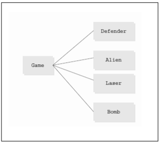
Fig. B.2: A Class Diagram
A class diagram can also show inheritance relationships between the classes: the subclasses and the super classes. As illustrated in figure B.3, to show that a class extends another, a line is drawn from the subclass to the superclass, with the arrowhead pointing to the superclass. Thus, Sprite is the superclass of both Alien and Bomb.
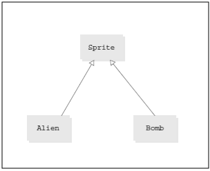
Fig. B.3: Class Diagram showing inheritance
If a class is an abstract class, the name of the class is followed by the text {abstract} to clarify its meaning.
An interface is described in the same way as a class in the form of a box. The difference is that the text <<interface>> precedes the name. A class that implements an interface has a dashed line with an arrowhead pointing to the interface box as shown in figure B.4.
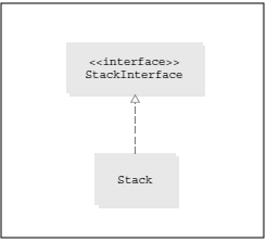
Fig. B.4: A Class and its interface. Arrow should be dashed
A class can be described in more detail, as described in Figure B.5. There are three compartments in this type of class diagram. The first compartment holds the class name, the second describes variables and the third describes methods. The visibility of an element can be described in a prefix as in Java: public, private, protected or default. In keeping with information hiding, the diagram is often drawn with the second compartment (the variables) omitted.
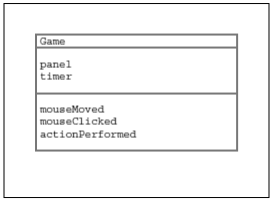
Fig. B.5: Class diagram showing the details of a class
A package diagram can be as shown in Figure B.6. The package is a rectangle with a tab at the top that holds the package name. Optionally, the classes within the package can be shown within the rectangle. For instance, the figure shows the class util consisting of the classes Random, Stack and ArrayList within the package.
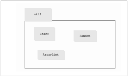
Fig. B.6 : A Package Diagram
An activity diagram consists of a sequence of activities. Thus, an activity diagram shows the flow of control through the software. An activity diagram can show:
An activity diagram can also illustrate a human activity such as delivering a specification. Actions are written in boxes with curved corners. The sequence of actions is shown by the arrows. A sequence starts with a blob symbol and ends with a special different symbol as shown in Figure B.7 below.
The diagram also uses the diamond-shaped branch symbol. Associated with each output from the branch is a condition. If the condition is true, the route is taken, just as in an if statement.
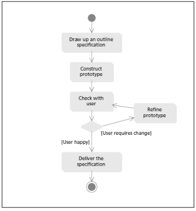
Fig. B.7: An Activity Diagram showing the delivery of a specification