1.1 Flowcharting Symbols
When you are drawing program or function-level flowcharts, there are only a handful of symbols you need to concern yourself with. As you move onto application and system flow diagrams, you encounter additional symbols. It seems each new tool for laying out system flow diagrams adds a few symbols or changes the meaning of them. Unless you stick to universal basics, system flow diagrams become very difficult for anyone who is not a techno geek to follow. The goal of a flowchart is as much to let the end user or customer “see” how things will work as the developer and IT types to envision a solution. Some of the tools on the market lose sight of that. Be careful when choosing programs to draw flowcharts for you.
A good many of these symbols you will never use. There are even more symbols that I simply didn’t provide. In part I didn’t provide them because they are not built into WordPerfect. The other part is quite simply that they don’t come up that often at the program or application level.
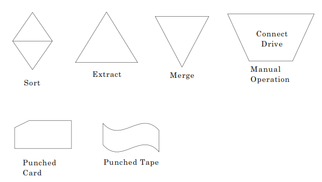
The last two symbols probably have some of you laughing and asking if I can still wear underwear or now need Depends. You have to remember that flowcharting started when developers had to work “close to the bare metal.” Many of us programmed in Assembler. This was as close as you could get to the machine instructions without hand entering octal values. (Don’t worry if your eyes glazed over on that, you don’t need to know it, just understand that it was laborious and difficult.)
Back in those days, a computer had to be “set up” to run a program. In many cases we didn’t even have full-blown operating systems. There were independent card reader subsystems, paper tape subsystems and, if your company had oceans of money to burn, a magnetic drum. When you flowcharted a “program,” you had to flowchart the entire execution. Hence, we have the “Manual Operation” symbol where you would instruct the computer operators to configure card readers, tape punches, etc. In many cases you would tell the operator to load a set of cards in front of your set of cards or your paper tape that would actually load the subsystem of the device(s) you needed into “core.” Memory wasn’t called RAM back then, it was called “core.” The reason is it actually was a magnetic core. It wasn’t until much later that RAM came along, followed by DRAM and a host of other types of RAM.
Here is an odd little tidbit for you. Any idea what the “ticker tape” was in a “ticker tape parade”? It had two sources. The first source was the brokers and stock exchanges. A paper tape device would print bid, ask and last sale for stock symbols as transactions happened. It wasn’t printing like you would think of today. Every time it printed it would make a ticking noise. This lead the industry to call the minimum price movement for a stock the “tick size.” Our second source of “ticker tape” was abandoned paper tape from computer rooms. Because the financial markets were some of the first businesses to use computers outside of the military, this made sense. Now, when people hold a “ticker tape” parade, they have to buy confetti.
As subsystems became better and better, they began to get “standardized.” The standard groupings of these subsystems came to be called “operating systems.” Computer memory started to get quite large in the 1970s. Digital Equipment Corporation (DEC) produced the PDP line of computers which had 64 K-words addressable and around 2 MEG of memory installable. That is correct, “words.” Bytes are 8 bits and words are 2 bytes. Today, most systems measure RAM as some grouping of bytes, so in today’s terms it would be 128K. In today’s world, compiler’s from Microsoft can barely create a program that prints “Hello Word!” to the screen using less than 128K, but back then we ran 30 to 64 users on a machine with that much.
Operating systems began providing “utilities” that programmers could use when writing programs and/or applications. The most used of these utilities was the SORT/MERGE utility. Every real operating system provides this utility. The Sort, Extract and Merge symbols allowed us to show in our flowcharts that we planned on using this utility.
The really old-timers would have a set of cards for input. They would indicate a Manual Operation for the computer operators to load the cards into the stand-alone Card Sorter and set the switches a certain way. Some time later they would come back and the cards would be sorted. There would be another manual operation for the operator to load the cards into one or more card readers and start the program. If you were lucky enough to get all of your cards into a card sorter, it could perform a “merge” for you by the simple virtue of sorting the entire bundle.
Disk drives turned Sort, Extract and Merge into a software-oriented process. Oddly enough, the “Extract” feature became the front-end process for Sort. As operating system sort utilities provided more and more functionality, they came with various methods for creating either “sort specification files” or “sort specification parameters.” Both sets allowed you to indicate which records you wanted the Sort utility to actually process. Typically, once you defined the “key” for the sort (i.e. account number, last name, etc.), you were allowed to add some sort of “selection” qualifier for that key. The sort utility created a temporary file with the records you selected, then it sorted those. It didn’t take long for people to figure out that if the temporary file name could be specified and Sort could be made to stop after creating it, then you just didn’t need to write extract programs.
Collate is an odd little symbol. As I recall, it started as a manual operation for operators to organize bundles of cards to be broken up between multiple card readers (too many for a single card reader). Then it morphed into being used for organizing reports that were printed on different printers. The last I remember it being used was for the massively expensive all-in-one copy-print machines. This was way before your sub $300 all-in-one copy-fax-print machines came out. We are talking about massive high speed printers that sometimes had copy functions built in. A collation device was hung on it that could sort and store anywhere from 12 to 30+ copies. Before we had really good printer control languages, the computer operator running the batch job had to ensure the printer was set to collate. He or she also had to sit there and pull out the reports as each tray got a completed one.
Let me explain the collate function a little bit more. Prior to printing systems that could bundle their output directly into an envelope stuffer, it was important. If you had a charge account with someone, you wanted to be the only one who got your statement. In the days of continuous form printing and hand collating, this wasn’t always the case. The collating device ensured that only your statement was on that tray, assuming the operator got the tray empty before it had to be re-used by the printer. The operator would either hand fold and stuff it or hand carry it to the stuffing machine.
As long as we are talking about odd computer hardware and terms, let me drop a couple more on you: burster and decollator – two of the noisiest machines to ever find their way into a computer room. It wasn’t good to handle all of this paper in a computer room, but the printers of the days needed the additional cooling found in the computer room. A burster would separate continuous form printouts into single sheets. You had to tell it the length of the form and start the form feeding from the correct way, then it sat there popping apart the perforations between pages. When you fed a report in, you had to feed it in backwards or facing the other way because the first sheet would end up at the bottom of the pile facing exactly the way it faced coming in. More than one newbie computer operator got to spend their afternoon “turning a report around” after feeding it in the wrong way.
The decollator was probably my favorite. These machines were an OSHA (Occupational Safety and Health Administration) disaster waiting to happen. Many things that got printed by computers back then, and even to some degree today, needed to be printed in multiple copies. Today, people buy el’cheapo ink jet printers and just print multiple copies, then hope for the best if they end up in court. What big business did was print on multi-part form, normally somewhere between two-and five -part forms. This meant that the exact same pre-printed form occurred that many times in a single perforated section. Early on they came with carbon paper between each sheet and later simply used “self-duplicating” pages. Once printed, the operator hand peeled the tractor-feed edges off the forms, then fed it through a decollator. The decollator had a stacking channel, or bin, for each “part” of the form and had these spinning slotted shaft-type things to wind up the carbon paper. They were the perfect tie catcher. I honestly think we avoided a lot of deaths in the IT industry by having the female operators run the decollator. It was a fair trade. They usually made the male operators lose their hearing running the burster. Dress codes seemed to always make the guys wear ties.
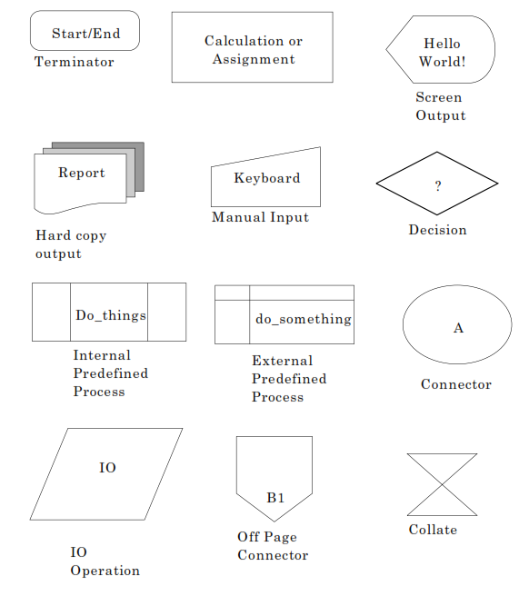
The off-page connector is just what you think it is. When you run out of room on a sheet of paper, you put one of these on the end of your line and put a label in it. You use the same connector and label on the start of the continuation page.
Our IO Operation symbol is used when reading or writing to files and databases. You use the hard copy output symbol when writing to a report file and the screen output symbol when writing to the terminal. When accepting input from the user, you use the manual input symbol.
The connector is usually a much smaller circle than I have drawn here. I needed to make it large enough to get the caption under it without a line break. Whenever you have multiple lines that need to intersect, you are supposed to use a connector. Instead of having 15 arrow heads going into one box, you mash the 15 arrow heads into the connector and have one line running from the connector to the box. (Don’t worry, you will understand before this chapter is over and not a lot of people do it.) Another use of the connector is the labeled connector as I have shown you.
When you are drawing a large flowchart, it is not uncommon to find yourself on the other side of the diagram needing to return. You can either create the world’s ugliest multiply bent line crossing over all other lines, or you can use a nice short line going to a labeled connector. You then use a labeled connector having the same label where you wish to return.
I used to flowchart on the back of continuous form. It was not uncommon for me to have single module flowcharts that were seven pages long. When you had a lot of things to do in a processing loop before you read your next record, there was simply no other way to get back to your input statement.
External predefined process encompasses operating systems library, home grown library and system service functions. In today’s world it also indicates stored procedures in a database engine. Ordinarily you just put the name of the procedure in the box. When drawing by hand I would put the name in the small area at the top of the symbol. A lot of electronic tools don’t give you that option.
Internal predefined process gets kind of tricky to define. Most people give you the “purist” definition, then bank heavily on you not flowcharting in the real world. It is a good bank in this day and age. The “purist” definition is you use this to indicate a subroutine that is a separate flowchart, but written as part of this program. Depending on the language used by your programming shop, this either worked for you or put you in a world of hurt.
Look back at the explanation for “external predefined process.” See that phrase “home grown library”? That is where the hurt comes in. Some programming languages enforce making every subroutine or function you write callable from anywhere. Some languages force you to decide at creation time whether your function/subroutine will be accessible from other programs. The hurt comes, not at the time of creation, but later in life. As you write more programs and others learn about your function/subroutine, it gets re-used. This means it gets placed in the “home grown library.” Your program didn’t change, but your flowchart is now out of date if you are using the purist definition.
The decision symbol has some odd uses. The normal use is single condition “if” testing. Usually there is just a Yes and No (or True and False) branch coming out of it. Fight off the temptation to “give it wings.” Have one line come out the bottom and the other come out a side. Using the side points for each condition only looks good in very short examples. When drawing out larger logic diagrams, it paints you off the page pretty fast.
I said it has some odd uses. They aren’t really odd, they just look odd to those unfamiliar with them. Most computer languages today have what is known as a switch, select or evaluate statement. The general explanation for these statements is that you do different things depending on the value of one variable. The variable name gets placed in the decision symbol, then you draw a line with a lot of drop points off it and label each drop point with the variable value. It drops into the action to be taken for that value. Don’t worry, I will provide an example later in this text.
Our calculation/assignment box is pretty much what it sounds like. In it you will find statements like SALES_TAX = NET_SALES * TAX_RATE. Don’t worry if you don’t understand those names, as understanding them isn’t a big hurdle.
Terminator should be the most straight forward symbol in flowcharting. It has caused more heated discussions than any symbol I know. You use one of these symbols to start your flowchart and another to end your flowchart. Shouldn’t be a problem, right? Guess again. The problems surface around what goes inside of the symbols.
Some camps became quite religious about using EXIT when the module is stand-alone and others just as deeply convicted about END. They argued strongly that EXIT should only be used for subroutines that do not return a value to their caller. Save your laughter, it gets better. Functions which return a value had some equally divided camps. Some believed strongly that it should be RETURN RET_VAL where RET_VAL was the name of the variable containing your return value. Others believed it should just be RETURN and the documentation for the function should stipulate the return value. One camp believed it should be EXIT RET_VAL because whatever language they were using for programming actually ended a function with that syntax. A small group of FORTRAN programmers used to champion the idea of the ending symbol being left blank. This was because in FORTRAN you assigned the return value to the function name and the code simply stopped.
Do you really want me to go into the arguments about the content of the starting symbol? We are just going to use START for stand-alone modules and ENTER for callable routines. Sometimes I will slip and use START all of the time. I will use STOP, EXIT, END or RETURN as I see fit on the last terminal. Please forgive me.
As I stated earlier, there are symbols I didn’t cover. Some things we will cover later as I take you further into logic, and others you will need to pick up on your own.
Knowing what the symbols are won’t do you much good if you don’t know how to use them.
1.2 Linear Sequence
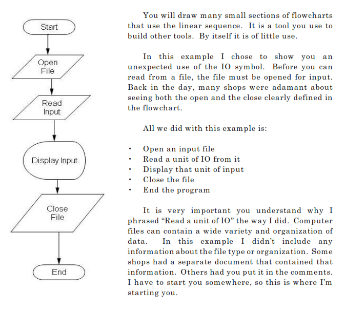
My display input symbol doesn’t have any preceding symbols that would convert binary data to display format. For the purposes of this discussion, you must assume that the input file has one line of readily displayable ASCII text. (If you don’t know what ASCII is, please take some time and search the Web for the definition and history.)
As you progress in the field of IT, you will encounter indexed files. These are files which contain both text and binary data organized in “records.” They will have one or more “keys” on them. A “key” is one or more fields defined at file creation time to be an “index” into the file. An “index” is used to quickly get to one or more records in the file. If the index is defined to identify only one record in the file, then it is called a “unique” index. This also translates into a “unique key.” Most index file systems require, some just recommend, that the first key defined for a file be a unique key. The first key is also usually called the “Primary Key.” Ordinarily, when you access a file via its primary key, you want to get exactly one record. The record that matches the key value you passed in.
I know I’m getting a little deep here this early in the text, but please plod through it. I’ll give you a small example later in this book. The point I’m trying to make right now is to be very careful about how you phrase things with respect to file IO.