The DIN standards devised by the German Industrial Standards Board are widely used for the connection of audio equipment. The connectors are shown below. The 3-way and 5-way 45 are the most common and connections for those are listed.
DIN 41524 DIN 41524 DIN 54322 DIN 45327 72° 45° 45° 60° 60° 90° 72°Microphone Input 1 O V 2
Tape recorder
inputs and
monitor outputs
Pin 3 available for polarizing voltage
Input 1
O V 2
Output 3
Input LH 1
Input RH 4
OV2
Pins 3 and 5
available for
polarizing voltage Input LH 1
Input R4 4
O V 2
Output LH 3
Output RH 5
Output, high Z3 O V 2
Output LH, high Z3 Output RH, high Z5
Amplifiers Output to tape 1 Output LH 1 OV2 Output RH 1 Input from tape 3 O V 2
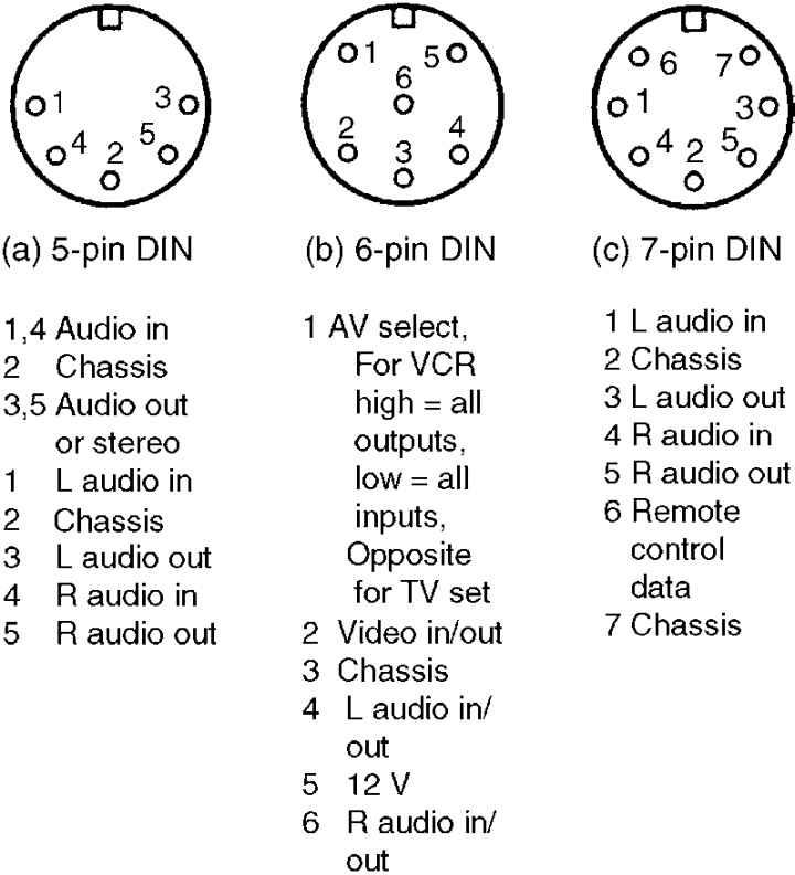
Input LH 3 Input RH 5 Variations on the above exist between different manufacturers.Standard pin configurations for videorecorders, televisions and videocameras are shown below. Many follow standard DIN connector pinouts, but videocamera and SCART connectors differ significantly.
SCART connectors, also known as Peritelevision or Euroconnector connectors, feature two control systems which allow remote control over the television’s or videorecorder’s functions.
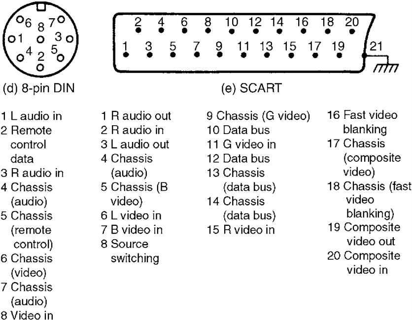
The simplest is a source switching input (pin 8) in which an external source (videorecorder, computer, etc.) can, by issuing a 12 volt signal, cause the television to switch to baseband inputs.
A more complex control system, called domestic data bus (D2B), is given through pins 10 and 12, in which serial data can be passed between controlling microprocessors in the television and external equipment. No standard yet exists for D2B.