Tuned resonant circuits composed of inductance and capacitance are used to generate alternating voltages of a specific frequency and to select a wanted frequency or band of frequencies from the spectrum. Figure 5.1 contains the diagrams of series and parallel resonant circuits including the resistances which account for the losses present in all circuits. In practice the greatest loss is in the resistance of the inductor, RL, with a smaller loss, rc, occurring in the dielectric of the capacitor.
Series A
Parallel A
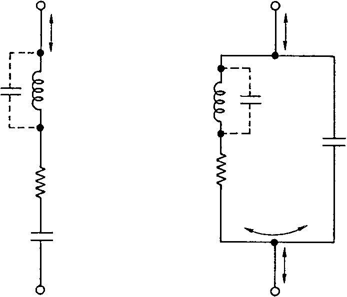 B
BOff resonance, the series circuit exhibits a high impedance to a voltage applied across A and B. This impedance is formed by the vectorial addition of the reactances of the inductance and capacitance at the applied frequency plus the resistances. Ignoring the dielectric losses and the very small stray shunt capacitance Cs, the resonant impedance is given by:
Z=
R
2+ ωL−1 2 ωC
79 where
R = resistance of components in ohms
ω = 2π × frequency in hertz
L = inductance in henries
C = capacitance in farads
At resonance the reactances cancel out and the impedance falls to approximately the value of the resistance, R, and a maximum line current will flow. Figure 5.2 shows the response curves of series and parallel circuits near resonance. The resonant frequency is given by:
1f = 2π√LCwhere
f = resonant frequency in hertz L = inductance in henries C = capacitance in farads
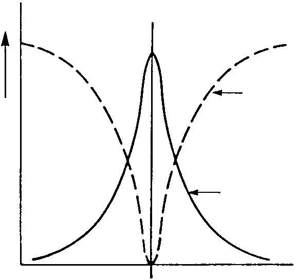 Series circuit
At resonance, calculated by using the same formula as for a series circuit, the impedance of a parallel tuned circuit is also resistive, and the circulatory current in the circuit is high producing the maximum voltage across the inductance and capacitance. Consequently, at resonance the minimum line current flows. The impedance at resonance or dynamic resistance of a parallel tuned circuit of moderate to high Q is given by:LRd = CR
whereRd = dynamic resistance of circuit
R = resistance of components in ohms
L = inductance in henries
C = capacitance in farads