A data pulse with a sharp rise- and fall-time produces harmonic frequencies and requires a wide bandwidth if it is to maintain its shape during transmission. Consequently, to transmit the data over a limited bandwidth the pulses must be shaped to reduce the harmonic content as much as possible without impairing the intelligibility of the signal. This is accomplished by the use of low-pass (Gaussian) filters of which the result is a string of smoother pulses, often referred to as ‘tamed’ (Figure 8.9(b)). Tamed FM permits high data rates within a limited channel bandwidth whilst maintaining acceptable adjacent channel interference levels.
10010110A serious problem with the transmission of binary data is that unless the clocks in the transmitter and receiver are synchronous the digits become confused, particularly where a continuous string of 1s or 0s occurs. Manchester encoding makes 1s change state from 1 to 0, and 0s from 0 to 1 during each digit period (Figure 8.9(c)), facilitating the synchronization of the clocks and rendering the digits more easily recognizable.
For binary data the number of signalling levels is not restricted to two (mark and space). Multi-level signalling has the advantage that one signalling element carries the information for more than one information bit, thus reducing the bandwidth requirement.
If the number of levels is increased to m,where m = 2n (i.e. n = log2m), the m-level data symbol is represented by n binary digits of 0 or 1 (see quaternary phase shift keying, Section 8.4.5). For example, in a quaternary data signal, m = 4 = 22 giving the binary sequences 00, 01, 10, 11 for each signalling level. This process is Gray coding where there is only one digit difference for each transition between adjacent levels. The number of levels is not restricted to four and 16 level quadrature amplitude modulation (QAM), where n = 4, is an efficient system.
In a Gray coded signal where each element contains n bits (n = log2m) and the signalling element rate is B bauds (elements per second), the transmission rate is B log2m bits per second.
The earliest modulation method. A continuous radio frequency wave (CW) is interrupted in a recognizable pattern (Morse code). To provide audibility the carrier is heterodyned with a beat frequency oscillator (BFO) in the receiver. The use of a modulated continuous wave (MCW) eliminates the need for a BFO but the bandwidth of the signal is increased. The problem with on/off keying is the lack of a reference level. If the signal strength temporarily falls below the sensitivity threshold of the receiver it appears to the operator as a series of spaces.
Because the level of a subcarrier is changed, AM sidebands are produced. Also, because the keyed waveform is non-sinusoidal harmonics occur. The occupied sub-carrier bandwidth for ASK is:
Bandwidth= 2Bwhere B = bit repetition rate (bits/second).
When the RF carrier is modulated its bandwidth is 2(fc +B) where fc = subcarrier frequency.
Although used for conveying digital information, frequency shift keying in reality employs frequency modulation. In its original form, developed for HF transmission, FSK changes the carrier frequency to indicate a 1 or a 0 but retains the nominal carrier frequency as a reference and to represent a mark. A downwards shift of carrier frequency by 170 Hz represents a space in the HF radio system.
Table 8.4 bit rates Standard ITU-T frequencies for variousBit rate (bps)
Frequencies 01 Subcarrier frequency
600
1200
up to 300 1700 1300 2100 1300 1180 980 1850 1650 1500 1700 1080 1750
Modern FSK uses two different modulation frequencies to represent 1s and 0s. If intersymbol interference (ISI) is to be avoided the separation of the tones must be more than half the bit rate, and a factor of 0.7 is often used. Standard ITU-T frequencies for various bit rates are given in Table 8.4.
The base bandwidth requirement is:Bandwidth = f2−f1+ 2B
The bandwidth of a modulated carrier is:
RF bandwidth= 2(f2+B)(narrow band FM)
Minimum shift keying (MSK) is a form of FSK where the frequency deviation is equal to half the bit rate.
Similar to MSK, the Gaussian filters improve the adjacent channel performance against a small cost (approximately 1%) in ISI while achieving high data transmission rates.
Fast frequency shift keying may either amplitude or frequency modulate the carrier. In binary FFSK, the data is changed in a modem to tones of 1800 Hz to represent binary 0 and 1200 Hz to represent binary 1. During transmission a binary 1 consists of 1 cycle of 1200 Hz, f1, and a 0, 11 cycles of 1800 Hz, f2, i.e. a bit rate of 1200 bps. For2
acceptable intersymbol interference the distance between the tones cannot be less than half the bit rate and the 600 Hz separation in FFSK represents the fastest signalling speed – hence the description – and minimum bandwidth. For this reason it is sometimes called minimum frequency shift keying (MFSK). The base bandwidth is the same as for FSK, but the RF bandwidth depends upon the system deviation. For example, on a 12.5 kHz channel spaced system carrying FFSK and complying with Radiocommunications Agency Code of Practice MPT 1317, deviation = 60% of system deviation = 1.5kHz:
f1 = 1200 Hz f2 = 1800 Hz B = 1200 bps
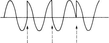
fmax = f2+B = 3 kHz and the mod. index m = max. dev./fmax < π/2 so the system is NBFM and the bandwidth = 2(f2+B) = 6 kHz. Where more data states than binary are to be transmitted, multistate FSK (M-ary FSK) is also possible where Mmaybeupto32states. Both FFSK and M-ary FSK are well suited to radio transmission as the change of state occurs while the signals are passing through zero, avoiding sudden phase changes (Figure 8.10(a)).
The minimum distance between the tones used in FFSK of 0.5 times the bit rate is not ideal for immunity to intersymbol interference (ISI).Logic 0 three half cycles 1800 Hz Logic 1 two half cycles 1200 Hz 1200 Hz 1800 Hz 1200 Hz
A separation of 0.7 times the bit rate would improve the ISI but increase the bandwidth.
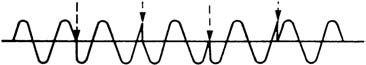
There are several variants of phase shift keying. Binary phase shift keying (BPSK or PSK) changes the phase of the carrier by 180æ at the zero crossing point (Figure 8.10(b)). No carrier frequency is present with PSK as half the time the carrier is multiplied by+1 and the other half by−1 and cancels out, but the reference phase of the carrier must be re-inserted at the receiver. The bandwidths occupied are the same as for ASK, i.e.:
Baseband = 2B
RF bandwidth (AM or NBFM) = 2(fc +B)
Differential phase shift keying (DPSK) advances the phase 90æ or 270æ at each change of logic state (Figure 8.11). Changing phase only at a change of logic state saves bandwidth which, for DPSK, is equal to the bit rate.
 +
+Data Phase change
0 +90°
1 +270°
 Dibit Phase change
 00 +45°
01 +135°
11 +225°
10 +315°
An important advantage of both FFSK and PSK over FSK is that because the moment of change is predefined it is possible to recover data more accurately. However, the transition between signalling states is not smooth requiring large and rapid phase shifts. Multilevel systems with less phase shift between elements are preferable.
Quaternary, or quadrature, phase shift keying (QPSK) is a fourlevel Gray-coded signalling method with 90æ phase shift between adjacent signalling elements (Figure 8.11(b)). If the signal is considered as a vector the points at π/4 (45æ), 3π/4 (135æ), 5π/4 (225æ) and 7π/4 (315æ) represent the transition points between states and the binary data.