Color
The NTSC camera acquires images in the color format YCbCr, where Y represents luminosity, Cb
the blue component, and Cr the red component. Each image must be converted to 16-bit RGB for
output on a standard color computer monitor. The function “ycbcr422pl_to_rgb565” performs this
conversion. Knowing how this function converts each pixel to RGB is relatively unimportant,
however, knowing the packed (5:6:5) RBG format is essential.
Before we ignore the ycbcr422pl_to_rgb565 function completely, it is useful to look at how it
operates. Find the run time of the function by examining the file “ycbcr422pl_to_rgb565.c” and
note that it must convert an even number of pixels at a time. If it were possible to have this
function process the whole color image at in one function call, how many clock cycles would the
function take? Since we are limited in the number of rows we can modify at a time, how many
clock cycles should it take to process the whole image one row at a time? To demonstrate the
overhead needed for this function, note how many clock cycles the function would take if it
converted the whole image two pixels at a time.
Figure 2.21.
RGB (5:6:5). A packed RGB pixel holds 5 bits for red, 6 bits for green, and 5 bits for blue.
Since each color is not individually addressable in the packed RGB format (e.g. bits representing
red and blue are stored in the same byte), being able to modify different bits of each byte is
necessary. To help clarify what bits are being set/cleared/toggled, numbers can be represented in
hex format. For example, the integer 58 can be represented by “00111010” in binary or by “3A” in
hex. In C, hex numbers are indicated with the prefix “0x.”
Example:
int black = 0x00; // black = 0
int foo_h = 0xF0; // foo_h = 240
int foo_l = 0x0D; // foo_l = 13
Another thing to note is that each pixel requires two bytes of memory, requiring two memory
access operations to alter each pixel. Also NOTE that in a row of input color data, the indexing
starts at 1. Thus RGB[1] contains red/green data and then RGB[2] contains the green/blue data –
both for the first pixel.
What is the packed RGB value for the highest intensity green? What is the value of the first
addressable byte of this ‘hi-green’ pixel? What is the value of the second byte?
Now, say you are given the declaration of a pixel as follows:
int pixel;
Write a simple (one line is sufficient) section of code to add a blue tint to a pixel. Do the same for
adding a red tint, and for a green tint (may require more than one line). Use the and (represented
by an ampersand) operator to apply a mask.
Implementation
The first part of this lab will require you to write a function to perform auto-contrasting. You
should use your function from prelab 2.1 to obtain the maximum and minimum values of the
image, and then create another function to do the appropriate scaling.
The second part of this lab will involve implementing some simple, and hopefully cool, color
effects.
Grayscale
Use the function you designed in prelab 2.1 to create an algorithm to auto-contrast the image.
Auto-contrast is accomplished by scaling the pixel value from the min-to-max range to the full
range. This effect is seen below:
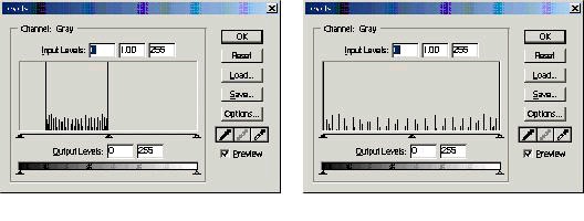
Figure 2.22.
(left) Frequency of a grayscale image with pixel intensities ranging in value from 32 to 128, and (right) Frequency of the same grayscale image after performing an auto-contrast.
Recall from “Introduction to the IDK” that the DSP has a floating point unit; the DSP will perform
floating point instructions much faster than integer division, quare-root, etc.
Example:
int opposite, adjacent;
float tan;
tan = ((float) opposite) / ((float) adjacent);
This function should be called similarly to the flip_invert function in the previous lab. Once you
have implemented your function, look for ways to optimize it. Notice that you must loop through
the image twice: once to find the minimum and maximum values, and then again to apply the
scaling. (Hint: the function dstr_rewind rewinds the image buffer).
Use the same core files for this part of the lab as were used in the previous lab. You may simply
make a copy of the previous lab’s folder and develop the necessary code from there.
Color
In this part of the lab, you will use the concepts from the prelab to implement certain effects.
Copy the directory “V:\ece320\projects\colorcool” to your W: drive.
We want to use a certain area of the screen as a "control surface". For example, the fingers held up
on a hand placed within that area can be used as a parameter, to control the image on the screen.
Specifically, we will use the total brightness of this control surface to control the color tint of the
screen.
You are given a shell program which takes in a color input frame in YcbCr format and converts it
to RGB. You will modify this shell to
1. Calculate the total brightness
2. Calculate the tint for each color component R, G and B.
3. Apply the tint to the image
Code Briefing
The code provided merely performs a color conversion required to go from the input NTSC image
to the output RGB image. The relevant streams of data are brought in using the in_luma, in_cr,
in_cb odd and even streams
The odd, even is done because the input YcbCr data is interlaced and the different "color"
components Y(luminance), Cr, and Cb are stored in different arrays, unlike RGB where the data is
packed together for each pixel. Thus the streams are accessed inside the color_conv_image
wrapper function. We then pass a line at a time to the color_conv component function which
converts and flips one line at a time.
We will need to modify the code here, in color_conv to achieve your goals. The control surface
will be a square block 100 by 100 pixels in the bottom left corner of the screen. The brightness
will be calculated by summing all the R, G and B values of all the pixels in this portion of the
screen. We then apply the tint effect as such:
if the total brightness is below a certain level 'X': use a red tint,
if the total brightness is above 'X' and below 'Y' : use a green tint,
if above 'Y' : use a blue tint
The tint has to be scaled too. For example, if brightness is less than X but close to it we need a
high blue. But if it's closer to zero we need a darker blue and so on. The scaling need not be linear.
In fact if you did the auto-contrast function you will have noticed that the floating point
operations are expensive, they tend to slow the system. This is more so in the color case, as we
have more data to scale. So try to use simple bit shifts to achieve the needed effect.
Right Shift : >>
Left Shift : <<
Masking : Use a single ampersand, so to extract the first red component: RGB[1] &
0xF8
Tips and Tricks
You're on your own now! But some things to remember and to watch out for are presented here, as
well as ideas for improvement. Remember:
The input is two bytes per pixel. Keep the packed RGB format in mind.
Also we process one line at a time from top to bottom. We cannot go back to previous lines to
change them. So we can only modify the tint of the screen below the control surface. What you
could do however is keep global variables for the different scalings in main. Then pass these to
color_conv by reference, and update it when converting colors. But perform the update after
using the existing scale values to scale the screen region above the control surface. This will
introduce a delay from scaling change to screen update. This can be solved by copying the
entire input to memory before outputting it but this is quite expensive, and we'll deal with
memory in the next section.
Be careful when performing masking, shifting and separting. Bring things down to least
significant set of bits (within a byte) to simplify thinking of the scaling. Also be careful not to
overlap masks, especially during shifting and adding
Here are a few recommendations:
Try to use the Y data passed to the color_con funtion to compute the brightness – much faster.
Also poke around and find out how to use the Cr, Cb data and scale those. It's far less expensive
and may produce neater results.
If something doesn't work, think things through again. Or better still take a break and then
come back to the problem.
Video Processing Part 3: Memory Management*
Introduction
In this project, you will learn how to combine the use of the external and internal memory systems
of the IDK, as well as how to use the TI-supplied library functions. It may seem daunting, but fear
not, there are only a few commands to learn. The key is to know how to use them well.
The project assignment will involve copying a portion of the input image and displaying it in a
different area of the screen. The area copied to should be quickly and easily adjustable in the code.
In addition to this, we will filter this copied portion and display it as well.
And you must refer to the following TI manuals available on the class website under the Projects
section. The sections mentioned in Video Processing Lab 1 are also important.
IDK Video Device Drivers User's Guide The Display and Capture systems are important – the figures on pages 2-7 and 3-8 are useful too.
IDK Programmer's Guide. Sections 2 and 5 are the ones needed. Section 2 is very important here. Keep a printout if necessary, it is useful as a reference.
Memory - The Basics
As explained in the previous lab, there are two sections of memory, internal and external. The
internal is small but fast, whereas the external is large but slow. An estimate of the sizes: 25K for
the internal, 16M for the external, in bytes.
As seen earlier, this necessitates a system of transferring memory contents between the two
memory systems. For example, an input color screen is in YCbCr format. This consists of 640 X
480 pixels with 8 bits per pixel. This results in 300 Kbytes, which cannot be stored in internal
memory. This same problem applies for the output buffer.
Thus it is best to use the external memory for storage of large chunks of data, and the internal
memory for processing of smaller chunks. An example of this, as seen in the previous lab, was
color conversion. In that system, we brought in the input frame line-by-line into internal memory.
We then converted the color space and stored the results in internal memory as well. Following
this, we transferred the results to external memory.
This is the basic overview of the need for the two memory systems. Next we will discuss the setup
and use of memory spaces, explaining the workings of the color conversion program
Memory - Setup
Firstly, please copy the directory below to your account so you can follow the code as we go
along.
V:\ece320\projects\colorcool
The program in this directory is a basic color conversion program which outputs the input frame
to the display.
Allocating Memory Space
The first step in using memory is to declare it, i.e. tell the compiler to setup some space for it.
This is done at the very beginning of the ‘main.c’ file.
1. Declare the type of memory space and it’s name. Use the #pragma DATA_SECTION
command. There are two parameters :
a) the name of the memory spaces
b) and the type – internal or external
2. Then specify the byte alignment using the #pragma DATA_ALIGN command. This is similar
to the byte alignment in the C54x. So, to store black and white images, you would use 8 bits.
But for RGB, you would use 16 bits.
// specifies name of mem space – ext_mem
// and type as internal memory – ".image:ext_sect"
// the data_align specification is the byte alignment – ours is
// 8 bits
#pragma DATA_SECTION(ext_mem,".image:ext_sect");
#pragma DATA_ALIGN(ext_mem,8);
// specifies name of mem space – int_mem
// and type as internal memory – ".image:int_sect"
// the data_align specification is the byte alignment – ours is
// 8 bits
#pragma DATA_SECTION(int_mem,".chip_image:int_sect");
#pragma DATA_ALIGN(int_mem, 16);
We then specify the size of the memory space. We use a variable for the basic unit size (e.g.
unsigned char for 1 byte) and a length for the number of basic units needed. Please note, the
memory space is not delineated by ‘image’ rows or columns, The system thinks it is one long
array of data, it is up to us to process this as separate lines of ‘image’ data.
// specify size as width 640
// height 480
// and 8 bytes per pixel
// which could represent an RGB screen of 640 X 480 with
// 2 bytes per pixel. Unsigned char = 8 bytes
unsigned char ext_mem[640 * 480 * 2];
// here we create 6 lines of RGB data of 640 columns each,
// 2 bytes per pixel
unsigned char int_mem[6 * 2 * 640];
Now have a look at the main.c file and take note of the memory spaces used. The internal memory
is of size 12 * 640. This single memory space is going to be used to store both the input lines from
the camera image and also the results of the color conversion, thus explaining its large size.
Basically the internal memory is partitioned by us for different buffers. The output data buffer
needs only 4*640 bytes thus it's space starts at
int_mem + (8 * cols); //cols = 640
and ends at 12*cols – which gives us 4*cols of space. Though it is useful to partition internal
memory in such a way, it is recommended not to. It is very easy to mess up the other data too, so
simple, so our solution would have been to create a separate memory space of size 4*cols.
The external memory, though declared here, will not be used in the program, however you may
need to allocate some external memory for this project lab assignment.
The INPUT and OUTPUT buffers and Main.c Details
Good examples of the external memory use are the input buffer (captured image) and output
buffer (to be placed onto the screen). There are a few steps in obtaining these buffers:
1. First, we open the capture and display devices in tskMainFunc() using
VDIS_open();
VCAP_open();
2. If the open calls are successful, we then call the color function to process the video feed
using
color(VCAP_NTSC, VDIS_640X480X16, numFrames);
This specifies:
the capture image format – NTSC
display image format and size
numFrames to run the system for – in our case one day to be passed on to the color function.
Please note, we merely specify the formats but do not configure the system to use these
formats, yet.
We then move on to the color(…) function within main.c
3. First we declare some useful pointers which we will use for the various images and their
components and so forth. The IMAGE structure holds a pointer to the image array (img_data).
In addition, it holds integers for the number of image rows (img_rows) and number of image
columns (img_cols).(Implementation Details in img_proc.h) Declare more of these structures
as needed for any memory spaces you create yourself. Furthermore, “scratch_pad” structures
hold information about the location and size of internal and external memories. This is another
use of pointers being used to hold the locations of the different memory spaces.
(Implementation Details in img_proc.h) We also configure the display and capture formats
using
VDIS_config(displayMode);
VCAP_config(captureMode);
Following this we enter the loop :
for (frameCnt=0; frameCnt<numFrames; frameCnt++)
This loop iterates for a set number of frames and processes them one at a time. And the lines
following this :
input = VCAP_getFrame(SYS_FOREVER);
output = (Uint16*)VDIS_toggleBuffs(0);
are used to obtain the capture and output frames. After this statement, ‘input’ will hold a
pointer to external memory where the captured frame is stored. The ‘input’ pointer holds
pointers ‘y1’, ‘c1’ etc to the different color component of the image. These color components
are in external memory as well. And ‘output’ will hold a pointer to a buffer in external
memory, to which we will write whatever we need to output to the screen. Basically the buffer
is the size of the output frame (640 X 480 X 2 bytes/pixel), and we can write what we wish to it.
And, the next time togglebufs(0) is called, everything we placed in that buffer will be put on the
screen. And a new buffer will be allocated, the pointer ‘output’ will be updated and we can now
write to the next frame. The next line
out_image.img_data = (unsigned char *) output;
updates the pointers we had setup. We then move on to the color_convert(..) routine. We pass
the memory pointers we had created so that our color_conv program can process the input
frame we obtained. In color_conv, we begin by setting up streams to bring in data and streams
to send out data. After that we begin the color-space conversion.
Memory Streams
Memory streams are structures used to facilitate the transfer of data between internal and external
memory. But why do we need a structure? Can’t we just do it manually?
You could, but you’d spend two months to do the same work as a single stream, which only takes
a few minutes (hopefully). So to cut a long story short, streams are your friends. They help
remove much of the complexity associated with internal/external memory transfers.
First, please make sure you’ve read the manual sections mentioned on page 1. There are two basic
types of streams : input and output. Input is a transfer from external to internal. Output is the
opposite. Think of bringing in and putting out.
For each type we need to specify various parameters, such source and destination addresses,
increments, size of transfer chunks and so forth. This specification is done once for each transfer
session (say, once for each image transfer), using the dstr_open command. We then use dstr_get
and dstr_put commands to tell the stream to bring in or put out data one chunk at a time.
Creating and Destroying Streams
Streams are dstr_t objects. You can create a dstr_t object and then initialize it using the
dstr_open() command. Basically, start with,
dstr_t o_dstr;
Then use the
dstr_open (…);
The dstr_open () specification is given in the manual. Some clarifications are made here. As an
example we will consider the output stream o_dstr in color_convert(). This stream is an output
stream. This stream is used to transfer data from internal memory to the screen output data buffer.
(we captured the buffer's memory location in the previous section using togglebufs(), it's memory
address is stored in the pointer out_image->img_data)
Arguments (note : out_rows = 480, out_cols = 640):
dstr_t *dstr
needs a pointer to the data stream object we wish to use. In our case this would be o_dstr.
void *x_data
takes a pointer to the location in external memory which we are using. In our program this is
specified in out_image->img_data. And since we are using an output stream, this argument
specifies the Destination of the stream. (This argument is the Source for an input stream)
int x_size
takes in the size of the external data buffer to which we are writing to. This specifies the actual
number of bytes of external memory we will be traversing. So this is NOT necessarily the full
size of the output buffer (i.e. NOT always 640 X 480 X 2) For our example we are writing to the
full screen hence we use
(2 * out_rows * out_cols)
which results in 640 X 480 X 2 bytes of data. An example of the exception is when we write to
only, say, the first 10 rows of the screen. In this case we would only traverse: 10 X 640 X 2
bytes. One more thing to note is that if you need to only write to the first 40 columns of the first
10 rows, you would still need to traverse the same amount of space and you would use 10 X 640
X 2 bytes again for this argument. In this case however, you will be skipping some of the data,
as shown later.
void *i_data
takes a pointer to the location in internal memory we are using. In our program this is specified
as out_data. And since we are using an output stream, this argument specifies the Source of our
stream. (This argument is the Destination for an input stream).
unsigned short i_size
is used to specify the total size of the internal memory we will be using. In our case we will be
writing one line of the output screen - (4 * out_cols) This is the amount we allocated earlier.
This evaluates to 640 * 2 * 2 bytes. The extra ‘2’ is needed for double-buffering, which is a
system used by the IDK for transferring data into internal memory. Basically, the IDM (image
data manger) needs twice the amount of internal memory as data transferred. i.e. one line is
worth only 640 * 2 bytes, but because of double buffering we allocate twice that for the IDM’s
use. Remember this when allocating memory space for internal memory.
unsigned short quantum
specifies the amount of data transferred in a single dstr_get or dstr_put statement. In our case it
would be (2 * out_cols). This evaluates to 640 * 2 bytes – one line of the output screen each
time we use dstr_put Now, if we were transferring only part of a line, let’s take the first 40
columns of the first 10 rows example. With each dstr_put, we will output only the first forty
columns of each row. Thus we are transferring 40 * 2 bytes in each call. But this can be
extended further. By use of the ‘dstr_get_2D’ we can transfer multiple lines of data. So we can,
say, transfer two full rows of the output screen (4 * cols) or in our mini-example this would
mean 2 * 40 * 2 bytes. Transferring of multiple lines is very useful, especially when using
filters which work on 2-D ‘regions’ of data.
unsigned short multiple
specifies the number of lines we are transferring with each call. Now this is not the conceptual
number of lines. It is the physical multiple of argument 6 that we are transferring. It is best to
leave this at one and modify argument 6 above.
unsigned short stride
needs the amount by which to move the external memory pointer. This gives us control over
how the lines are extracted. In our case, it being the simplest, we move one line at a time :
2*out_cols The stride pointer is especially useful when creating input streams. For example you
can pull in overlapping lines of input. So you can pull in lines 1 and 2 in the first dstr_get().
The next dstr_get() can pull in lines 2 and 3 or you can setup it up to pull lines 3 and 4 or 4 and
5 or ….. depending on the stride. In particular, this is useful in Sobel (edge-detect) filtering,
where you need data above and below a pixel to evaluate the output.
unsigned short w_size
is the window size. For transferring a single line at a time we would use '1' here, and the system
will recognize this is as one line double-buffered. But if we needed to transfer two lines we
would merely submit '2' as the argument.
dstr_t dir
specifies the type of stream. Use DSTR_OUTPUT for output stream and DSTR_INPUT for
input stream.
Once a stream is created, you can use the get and put commands in a loop, to bring in or put out
line/s of data. Calling dstr_get on an input stream will give you a buffer where data is present to
be read off. And calling an output stream will give you a buffer to which you can write data
(which will be transported out on the next dstr_put call).
Remember, you have to be careful how many times you call these functions as you so not want to
overflow. For example in our output example, we could call the dstr_put() upto 480 times – the
number of single row transfers. Anymore, and the system may crash.
Also please remember to close the stream once you are done with it, i.e after all iterations. See the
color_convert function to see when we close the streams using dstr_close(…). This is VERY
important, since not closing a stream will cause random crashing of your system. The system may
seem to run as you expected, but it will crash, if not after 1 second, then after 1 minute or 1 hour.
This problem is one of