5.2. Enhanced Educational Features for Teaching with
National Instruments Multisim*
Enhanced Features for Teaching
Overview
Multisim is used in colleges and universities around the globe. It has become an essential academic tool. Academic features available in Multisim provide students with intuitive methods for easily exploring circuit theory.
Because National Instruments products can be applied at the introductory, advanced and professional levels, students’ proficiency with the software will naturally grow over time, allowing them to focus on tackling increasingly complex content and projects, not on learning new tools over and over as their needs increase.
Prototyping
3D Virtual Components
Multisim includes a set of components specifically designed for students with little to no experience working with parts in real life. When placed on the schematic, these 3D virtual components appear exactly as they look in the real world. These components are available in the Basic group of the Master Database, under the 3D_VIRTUAL family.
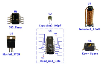
Figure 5.5.
3D Virtual Components
Animated Components
Animated components provide students with visual feedback on circuit operation during simulation. Examples of animated components include LEDs, 7-Segment displays, and other interactive components such as switches and potentiometers. Animated components are located throughout Multisim's databases.
Rated Components
Rated Componentshave tolerances just like real-world parts. Users can control the tolerance level by editing the part properties. If the power being dissipated by a virtual rated resistor is above the threshold, the resistor will "explode" on the schematic, and act as an open circuit. Rated Virtualcomponents can be found in the RATED_VIRTUAL family of the Basic group in the Master Database.
3D Virtual Breadboard
Multisim also includes a 3D Virtual Breadboard. The breadboard can be used to teach students important prototyping techniques. Nets and components will turn green on the schematic when their corresponding breadboard elements have been correctly wired. The breadboard also includes a Design Rules Check (DRC) and Connectivity Check.
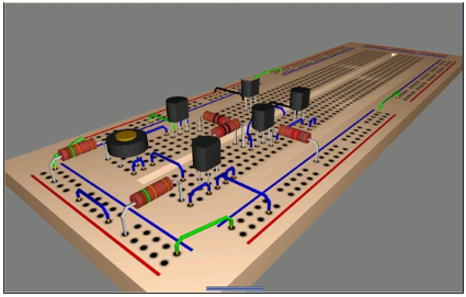
Figure 5.6.
3D Virtual Breadboard
3D Virtual ELVIS
In addition to the standard 3D Virtual Breadboard, students also have the option to create NI ELVIS schematics, which will have a corresponding 3D ELVIS representation. The virtual instruments included with NI ELVIS such as the function generator, oscilloscope, and variable power supplies have also been modeled. To create an NI ELVIS schematic, click File/New/ELVIS Schematic.
To access the ELVIS virtual instruments, double-click on the terminals corresponding to the desired instrument.
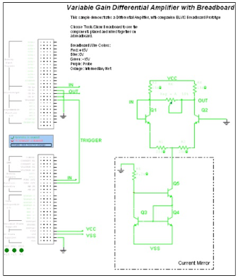
Figure 5.7.
3D NI ELVIS Schematic
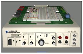
Figure 5.8.
3D Virtual NI ELVIS
Troubleshooting
Circuit Faults
Instructors have the ability to insert faults into schematics, and have students hone their troubleshooting skills by trying to find the faults. The injected faults can be hidden to force students to apply fundamental techniques of troubleshooting. To add a fault into a component, double-click on the component, and select the Faults tab.
Faults include open circuits on a particular terminal, short circuits between two pins of a component, and resistive losses measured in Ohms.
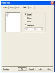
Figure 5.9.
Adding Faults to Components
Black Boxes
Instructors can also use subcircuits as black boxes, and engage students in more sophisticated circuit analysis techniques. To create a black box problem, use the information in Section I on creating subcircuits. Note: Hierarchical blocks should not be used as black boxes because the internal circuitry is stored in a separate file, which students would be able to view.
Circuit Restrictions
Circuit restrictions play a very important role when creating black box problems, or inserting circuit faults. Restrictions allow instructors to prevent students from seeing subcircuits, hide the faults, and limit the number or available components and instruments. In this manner, as an example, it is possible to force students to use an oscilloscope to make gain measurements when determining the bandwidths of filters, as a bode plotter or AC analysis may not always be available.
Global and circuit restrictions are available under the Options menu. Restrictions are locked by password.
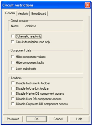
Figure 5.10.
Circuit Restrictions Dialog Box
Solutions