1.2. Interactive Schematic Capture and Layout in
National Instruments Multisim*
Schematic Capture in MultiSim
The Benefits of Integrated Capture and Simulation
Multisim provides users with the unique ability to capture and simulate from within the very same integrated environment. The advantages of this approach are many. Users new to Multisim do not have to worry about sophisticated SPICE (Simulation Program with Integrated Circuit Emphasis) syntax and commands, while advanced users have easy access to all SPICE details.
Multisim makes capturing schematics easier and more intuitive than ever. A spreadsheet view allows users to easily modify characteristics of any number of components simultaneously: from PBC footprint to SPICE model. Modeless operation provides the most efficient way of placing components and wiring them together. Working with both analog and digital multisection components is intuitive and simple.
In addition to traditional SPICE analyses, Multisim allows users to intuitively connect virtual instruments to their schematics. Virtual instruments make it fast and easy to view interactive simulation results by replicating the real-world environment.
Multisim also provides special components known as interactive parts which can be modified while a simulation is running. Interactive parts such as switches and potentiometers, will immediately and accurately affect the results of simulation.
When the need arises for more advanced analysis, Multisim delivers over 15 sophisticated analyses. Some examples of analyses include AC, Monte Carlo, Worst Case, and Fourier.
Provided natively within the Multisim environment is a powerful Grapher, which allows the customized viewing of simulation data and analyses.
The integrated capture and simulation environment provided by Multisim is a natural fit for any circuit designer, and will save both time and frustration throughout the entire circuit design process.
The Multisim Environment
Introducing the Multisim Environment
Multisim’s user interface consists of the basic elements, illustrated in Figure 1 below.
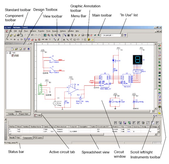
Figure 1.3.
The MultiSim Environment
The Design Toolbox
The Design Toolbox is used to manage various elements in the schematic. The Visibility tab lets you choose which layers to display on the current sheet on the workspace. The Hierarchy tab contains a tree that shows the dependencies of the files in the design that you have open. The Project tab displays information about the current project. Users can add files to the existing folders of the current project, control access to files, and archive designs.
Configuring global options
Global options allow users to configure specifics of the Multisim environment. They can be modified by accessing the preferences dialog box. Choose Options/Global Preferences. The Preferences dialog box appears, offering you the following tabs:
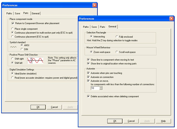
Figure 1.4.
Various Global Preferences
Configuring sheet options
The Sheet Properties dialog box is used to set up the preferences for each sheet. These preferences are saved with the circuit file so that if the circuit is opened on another computer, it will use the same settings.
The sheet specific settings are arranged in the following tabs:
Consult the Multisim User Guide or Multisim helpfile for a detailed description of each sheet property.
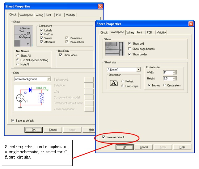
Figure 1.5.
Various Sheet Properties
Customizing the user interface
The Multisim user interface is highly customizable. Customizations are context sensitive. Toolbars may be docked in various positions and orientations. The contents of the toolbars may be customized. New toolbars may be created. The menu system is fully customizable, including all pop-up menus for the various object types.
As well, the keyboard shortcut system is customizable. This allows for key combinations to be assigned to any command that may be placed in a menu or on a toolbar.
Note: To avoid interfering with interactive simulation, it is recommended that users only assign commands to key combinations (such as Ctrl-E).
For example, the toolbars and docking windows may be re-configured as you move from a circuit sheet to a description sheet.
To customize the user interface, select Options/Customize User Interface. Using the Customize dialog, users can create or modify toolbars, assign or change keyboard shortcuts, customize and create menus, and modify the way the user interface appears.
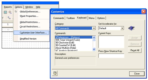
Figure 1.6.
Customize Dialog Box