4. DESIGN AND FABRICATION
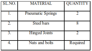
4.1. MATERIALS REQUIRED
4.2. EQUIPMENTS USED
• Arc welding equipment
• Portable Grinding Machine
• Drilling machine
• Hacksaw Blade
• Ball peen hammer
• Spanner
• Chipping hammer, etc.,
4.3. FABRICATION PROCESS
• Materials required to do the project are purchased.
• Then a reconnaissance was carried out about the methods through which the project was to be done.
• Finally a most efficient and economical method was selected for the experimentation.
• As Pneumatic spring is our major capital it is essential to have a study over the equipment.
• A vehicle spring comprising a plurality of independently mounted cylinders and valves for maintaining a uniform pressure in the cylinders and the source of fluid pressure supply, substantially as described.
• It comprising of a plurality of independent mounted cylinders and pistons arranged for reverse operation one of said cylinders and pistons operating in one direction being of greater power than the combined cylinders and pistons operating in the opposite direction, substantially as described.
• A vehicle spring comprising a central vertically disposed cylinder, piston, and piston rod, and two cylinders, pistons, and piston rods one upon each side of the central cylinder, piston and piston rod and inclined with relation thereto, substantially as described.
• Initially the steel bars of above mentioned specifications are welded with the help of arc welding equipment to obtain a shape of rectangular frame.
• Then another one frame is welded with the steel bars but its cross sections are slightly smaller compared to the previous one, that in can slide within the outer frame.
• The two steel frames are hinged by means of two hinged joints.
• Now the project is in the form of two rectangular frames that can slide with respect to each other. The outer frame is considered to be the vehicle base, while the inner frame is the trailer.
• Then the outer and inner frames are drilled with 8mm drill bit in upright drilling machine.
• The pneumatic springs are joined with nut and bolts on either side of the frame.
• At normal position, the pneumatic spring is in compressed position due to the self weight of the frame and only a small force is enough to lift the frame due to the application of the compressed air inside the pneumatic spring.
• This is the working principle of our project and it will eliminate the problems that are defined in the section problem definition.
• Finally finishing works are carried out like chipping the extra projections, remove the chips by wire brush, painting the project with suitable colours, etc.,