!
KndNKffector
C
B
A
x
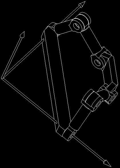
Fig. 10 a Spatial Six-Link Mechanism with a Straight line Translational End-Effector
From the above analysis, it is not difficult to find that the two kinematic chains ,0+ and
4#D can surely guarantee the pure straight line translation of the end-effector +D so long
as $,0+ and $4#D do not descend in ranks. To analyze the sensitivity of the structure stability to the angle @ , one should turn to the equations (37) and (38) and investigate the
resultant terminal constraints, which can be expressed with:
)1 cos@
0
0 0&
'
$
'0 sin@
0
0 0$
+
'0
0
0
0 0$
+D
$
!@"# '
$
(47)
'0
0
sin@
0 0$
'
$
0
0
2
@
'
cos
1 0$
'(0
0
0
0 1$%
'
.
where cos@ #
and sin@ #
.
2
2
2
2
' 6 .
' 6 .
If the terminal constraints denoted by +
+D
$
!@" are well conditioned, the mechanism will
have fine structure stability. From equations (29) and (47), one can find that the end-effector
will have one straight line translation along
+
3 -axis so long as
1
!'$( $+D !@ ",.
/
# 5 , which can
0
-
be immediately transformed to investigate the following sub matrix of +
+D
$
!@":
490
Parallel Manipulators, Towards New Applications
)1 cos@
0
0 0&
'
$
'0 sin@
0
0 0$
!
, @ " # '0
0
sin@
0 0$
'
$
'0
0
2 cos@ 1 0$
'
$
(0
0
0
0 1%
Letting 467! !
, @ " # 0 , one immediately obtains @ # 0 or @ # G . Therefore, in order to keep
the end-effector +D have one straight line translation along 3 -axis, there will be @ 3 0 and
@ 3 G . So, the rigid guidance mechanism synthesized in this chapter has a wider adaptation
of angle between the planes of its two kinematic chains. Now, the sensitivity of the structure
stability to the angle @ of the mechanism can be judged by the condition number of matrix
!
, @ " (Kelley, 1995). Let
1 " .
Hm89/ , , ,
-H$)! , "
1
0
-
#
2
,
,
#
1
2
#
(48)
2
2
1 " .
min
H
/ , , ,
0
-
where -H$)! , "2 indicates the condition number of matrix , , , indicates the 2-norm of
2
matrix
"
"
, , and 1
H , , ,.
/
indicates the eigenvalues of matrix , , .
0
-
y
K
z
F
D
KndNKffector
o
C
B
A
x
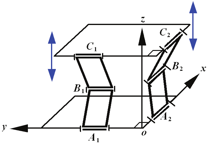
Fig. 11 a Spatial Six-Link Mechanism with the Best Structure Stability
The solution of equation (48) is:
G
@ #
(49)
2
Mo9ility of <patial Paral el Manipulators
491
Equation (49) indicates that the mechanism will have the best structure stability when
G
@ # , which is shown in Fig. 11. Compared with Peaucellier-Lipkin eight-link linkage, the
2
spatial six-link mechanism synthesized in this chapter has the least links and revolute joints,
and the whole end-effector +D can make an exact straight line translation while Peaucellier-
Lipkin eight-link linkage can only allow one specified point to make such a motion.
As a matter of fact, the mechanism shown in Fig. 11 is a Sarrus linkage. However, the
mechanism proposed here does not necessarily require that the two kinematic chains must
within two orthogonal planes which are needed for Sarrus linkage. The so-called Sarrus
linkage, which is shown in Fig. 12, is a linkage that converts circular motion to linear motion
by using hinged squares. The square end-effector 1
+ + 2 can make an exact straight line
translation along 3 -axis which shows better properties both in mechanical structure and in
kinematics than those of Peaucellier-Lipkin eight-link linkage. However, because of the
limited workspace and the uneconomic mechanism architecture, the restrictions of Sarrus
linkage shown in Fig. 12 compared with the one shown in Fig. 11 are obvious.
Fig. 12 the Structure of Sarrus Linkage
z
K
D
F
y
o
G
KndNKffector
B
C
A
x
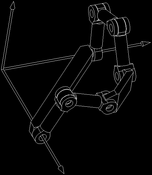
Fig. 13 Configuration of the Spatial Seven-Link Mechanism
492
Parallel Manipulators, Towards New Applications
As mentioned in step 6, in order to keep the twists of the chain to be equivalent to the twist
basis, the rank of the twists of each kinematic chain synthesized through equation (34)
should equal the dimension of its twist basis. Therefore, if one or more such twists are
added to each kinematic chain, the free motions of the end-effector will not be changed. As
an example, the mechanism shown in Fig. 13 is the derivative form of that in Fig. 10 by
adding one twist 1
I
$ to the kinematic chain 4#D . Where
$ # 0 1 0 2 3
0 2
I
!
I
" "
I
The two kinematic chains of the end-effector +D are now changed to be ,0+ and 4#I D
1
.
The twists of them two are:
; $
# $
$
$
,0+
B ,4 04 +4
1
1
1
C
:
9 $
# $
$
$
$
4#ID
B 44 #4 I4 D4
2
2
2
2
C
It is not difficult to find that the terminal constraints of kinematic chains ,0+ and 4#I D
1
are still expressed by equation (36). And therefore, the free motion of the end-effector +D is
still a straight line translation along 3 -axis shown in Fig. 13. As a result, the free motions of
the end-effector will not be changed if one or more revolute joints whose Pl cker
coordinates have the form of equation (44) are added in the second kinematic chain.
Similarly, the free motions of the end-effector will not be changed either if one or more
revolute joints whose Pl cker coordinates have the form of equation (41) are added to the
first kinematic chain.
Steering rod
KndNKffector
Aehicle Body
:heel
:heel
Transmission Axles
Left: Front Suspension Right: Rear Suspension
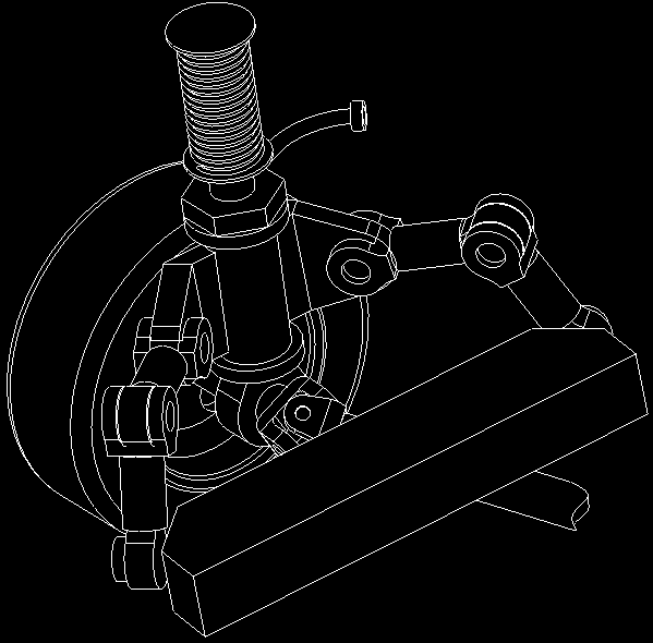
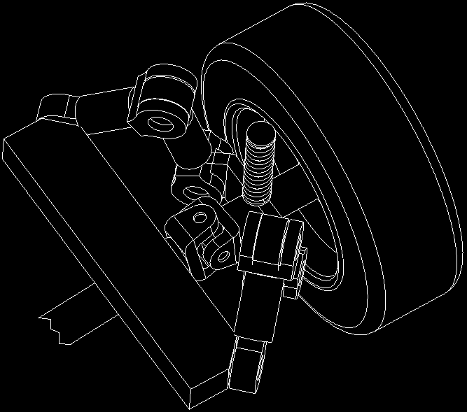
Fig. 14 a Front Suspension and a Rear Suspension
Mo9ility of <patial Paral el Manipulators
493
For engineering applications, the end-effector +D in Fig. 11 or Fig. 13 can be utilized as the
guiding equipment of a mechanism that requires a precise linear translation, such as the
independent suspension of automobile. Because the end-effector of the rigid guidance
mechanism can make an exact straight line translation, the front and rear suspensions made
up of such a mechanism shown in Fig. 14 allow the orientation and position parameters of
the wheels such as kingpin, caster, camber, and axes distance and wheel track to be
constant. These merits not only enhance the ride and handling of the vehicles, but also
reduce the wearing of the tires during jounce and rebound.
D5#E%28(34'%2#
This chapter focuses on the mobility analysis and synthesis of spatial parallel manipulators.
It focuses on developing an analytical methodology to investigate the instantaneous DOF of
the end-effector of a parallel manipulator and the instantaneous controllability of the end-
effector from the viewpoint of the possible actuation schemes for the parallel manipulator.
Via comparing the differences and essential mobility of a set of underactuated, over
actuated and equally actuated manipulators, this chapter demonstrates that the
underactuated, over actuated and fully actuated manipulators are all substantially equally
actuated mechanisms. This work is significantly important for a designer to contrive his or
her manipulators with underactuated or over actuated structures. Based on the analytical
model of the DOF of a spatial parallel manipulator, this chapter also investigates a general
process to synthesize the manipulators with specified mobility. The outstanding
characteristics of the synthesis method are that the whole process is also analytical and each
step can be programmed at a computer. Because of the restrictions of the traditional general
mobility formulas for spatial mechanisms, a lot of mechanisms that might not be
synthesized directly with the general mobility formulas could be synthesized with this
analytical theory of degrees of freedom for spatial mechanisms.
F5#G8H2%C(17;1<12)4#
This research was supported by FANEDD under Grant 200741 and the National Natural
Science Foundation of China under Grant 50425516. The authors gratefully acknowledge
these support agencies.
I5#J1+1012814#
Arsenault, M. & Boudreau, R. (2006). Synthesis of Planar Parallel Mechanisms While
Considering Workspace, Dexterity, Stiffness and Singularity Avoidance, ASME
Journal of Mechanical Design, Vol. 128, No. 1, (January, 2006)69-78 ISSN: 1050-0472
Ball, R. S. (First Published 1900, Reprinted 1998). a Treatise on the Theory of Screws,
Cambridge University Press, ISBN 0-521-63650-7, Cambridge
Birglen, L. & Gosselin, C. M. (2006a). Geometric Design of Three-Phalanx Underactuated
Fingers, ASME Journal of Mechanical Design, Vol. 128, No. 2, (March 2006)356-364,
ISSN: 1050-0472
494
Parallel Manipulators, Towards New Applications
Birglen, L. & Gosselin, C. M. (2006b). Grasp-state plane analysis of two-phalanx
underactuated fingers, Mechanism and Machine Theory, Vol. 41, No. 7, (July
2006)807-822, ISSN: 0094-114n
Chakraborty, N. & Ghosal, A. (2004). Kinematics of Wheeled Mobile Robots on Uneven
Terrain, Mechanism and Machine Theory, Vol. 39, No. 12, (December 2004)1273-
1287, ISSN: 0094-114n
Dai, J. S. & Jones, J. Rees. (1999). Mobility in Metamorphic Mechanisms of
Foldable/Erectable Kinds, ASME Journal of Mechanical Design, Vol. 121, No. 3,
(1999)375-382, ISSN: 1050-0472
Gogu, G. (2005a). Mobility of Mechanisms: a Critical Review. Mechanism and Machine
Theory, Vol. 40, No. 9, (September 2005) 1068-1097, ISSN: 0094-114n
Gogu, G. (2005b). Mobility and Spatiality of Parallel Robots Revisited via Theory of Linear
Transformations, European Journal of Mechanics A/Solids, Vol. 24, No. 4, (July-
August 2005) 690-711, ISSN: 0997-7538
Gosselin, C. M. & Lalibertd, C. T. (1998). Underactuated Mechanical Finger with Return
Actuation , Patent Number: 5762390, Date of Patent: June 9, 1998,
http://robot.gmc.ulaval.ca/en/publi/patents.html.
Huang, *.; Kong, L. F. & Fang, Y. F. (1997). Theory of Mechanism of Parallel Robotics and
Control, Machinery Industry Press, ISBN: 7-111-05812-7, Beijing
Huang, *.; *hao, Y. S. & *hao, T. S. (2006). Advanced Spatial Mechanism, Advanced
Educational Press of China, ISBN:7-04-019265-9, Beijing
Hunt, K. H. (1978). Kinematic Geometry of Mechanisms, Oxford University Press, ISBN 0-
19-856124-5, Oxford
Jain, A. & Rodriguez, G. (1993) An Analysis of the Kinematics and Dynamics of
Underactuated Manipulators, IEEE Transactions on Robotics and Automation, Vol.
9, No. 4, (August 1993)411-422, ISSN: 1042-296n
Kelley, C. T. (1995). Iterative Methods for Linear and Nonlinear Equations, North Carolina
State University, Society for Industrial and Applied Mathematics, ISBN:
0898713528(pbk.), Philadelphia
Kempe, A. B. (1877). How to Draw a Straight Line, London: Macmillan. Cited by Henderson,
D. W. & Taimina, D., http://kmoddl.library.cornell.edu/tutorials/11/.
Kumar, V. (1992). Instantaneous Kinematics of Parallel-Chain Robotic Mechanisms, ASME
Journal of Mechanical Design, Vol. 114, (September 1992)349-358, ISSN: 0738-0666
Lalibertd, T. & Gosselin, C. M. (1998). Simulation and Design of Underactuated Mechanical
Hands, Mechanism and Machine Theory, Vol. 33, No. 1-2, (January-February
1998)39-57, ISSN: 0094-114n
Murakami, T. et al. (1989). Development of a new multi-link front suspension, SAE 890179.
Phillips, J. (1984). Freedom in Machinery, Vol. 1: Introducing Screw Theory, Cambridge
University Press, ISBN 0-521-23696-7, Cambridge
Phillips, J. (1990). Freedom in Machinery, Vol. 2: Screw Theory Exemplified, Cambridge
University Press, ISBN 0-521-25442-6, Cambridge
Mo9ility of <patial Paral el Manipulators
495
Phillips, J. R. & Hunt, K. H. (1964). On the Theorem of Three Axes in the Spatial Motion of
Three Bodies, Australian Journal of Applied Science, Vol. 15, (1964) 267-287, ISSN:
0572-1156
Raghavan, M. (1996). Number and Dimensional Synthesis of Independent Suspension
Mechanisms, Mechanism and Machine Theory, Vol. 31, No. 8, (November,
1996)1141-1153, ISSN: 0094-114n
Raghavan, M. (2005). Suspension Synthesis for N:1 Roll Center Motion, ASME Journal of
Mechanical Design, Vol. 127, No. 4, (July 2005) 673-678, ISSN: 1050-0472
Rotman, Joseph J. (2002). Advanced Modern Algebra, Prentice Hall, (May 2002) ISBN :
0130878685
Shigley, J. E. & Uicker, J. J. (1980). Theory of Machines and Mechanisms, New York:
McGraw-Hill Companies, Inc. , ISBN: 0070568847, New York
Simionescu, P. A. & Beale, D. (2002). Synthesis and Analysis of the Five-Link Rear
Suspension System Used in Automobiles, Mechanism and Machine Theory, Vol. 37,
No. 9, (September, 2002)815-832, ISSN: 0094-114n
Suh, C. H. (1989). Synthesis and analysis of suspension mechanisms with use of
displacement matrices, SAE 890098.
Tsai, L.-W. (2001). Mechanism Design: Enumeration of Kinematic Structures According to
Function, CRC Press LLC, ISBN 0-8493-09018, Florida
Waldron, K. J. (1966). The Constraint Analysis of Mechanisms, Journal of Mechanisms, Vol.
1, (1966)101-114, ISSN: 0094-114n
Yan, H.-S. & Kuo, C.-H. (2006). Topological Representations and Characteristics of Variable
Kinematic Joints, ASME Journal of Mechanical Design, Vol. 128, No. 2, (March,
2006)384-391, ISSN: 1050-0472
Yi, B.-J. & Kim, W. K. (2002). The Kinematics for Redundantly Actuated Omnidirectional
Mobile Robots, Journal of Robotic Systems, Vol. 19, No. 6, (June 2002)255 267,
ISSN: 0741-2223
Yiu, Y. K. & Li, *. (2003). Trajectory Generation for a 2-dof Over-actuated Parallel
Manipulator with Actuator Speed and Torque Limits Consideration, Proceedings
2003 IEEE International Symposium on Computational Intelligence in Robotics and
Automation, pp.1058-1063, ISBN: 0-7803-7866, July 16-20, 2003, Kobe, Japan.
*hao, J.-S. et al. (2004a). A New Method to Study the Degree of Freedom of Spatial Parallel
Mechanisms. The International Journal of Advanced Manufacturing Technology,
Vol. 23, No. 3-4, (February 2004) 288-294, ISSN: 0268-3768
*hao, J.-S.; *hou, K. & Feng, *.-J. (2004b). A Theory of Degrees of Freedom For Mechanisms,
Mechanism and Machine Theory, Vol. 39, No. 6, (June 2004)621-643, ISSN: 0094-
114n
*hao, J.-S. et al. (2006a). Re-analysis of the Degree-of-Freedom Configuration of the
Platforms in Spatial Parallel Mechanisms with Constraints Spaces, The
International Journal of Advanced Manufacturing Technology, Vol. 28, No. 1-2,
(February 2006)190-196, ISSN: 0268-3768
496
Parallel Manipulators, Towards New Applications
*hao, J.-S. et al. (2006b). The Free Mobility of a Parallel Manipulator, Robotica, Vol.24, No.5,
(September 2006)635-641, ISSN: 0263-5747
*hao, J.-S.; Feng, *.-J. Dong, J.- n. (2006c). Computation of the Configuration Degree of
Freedom of a Spatial Parallel Mechanism by Using Reciprocal Screw Theory,
Mechanism and Machine Theory, Vol. 41, No. 12, (December 2006)1486-1504, ISSN:
0094-114n
22
Feasible Human-Spine Motion Simulators
Based on Parallel Manipulators
Si-Jun Zhu1,2, Zhen Huang2 and Ming-Yang Zhao1
1 Shenyang Institute of Automation (CMS)
2 Yanshan University
P.R. China
1. Introduction
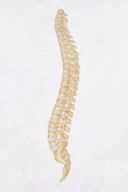
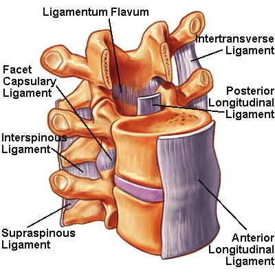
In biological kinematics, motion of a spine is realized by a number of functional spinal units
(FSU), as shown in Fig.1 (spineuniverse.com). Each FSU consists of two adjacent vertebras
and physiological organization joining FSUs end-to-end (Hou, 2005). Owe to the spine,
vertebrates have more flexible torsos than others. To understand, simulate and utilize the
motion of vertebrate’s torso, international researchers have made many bio-vertebrate
robots such as robotic dog (bostondynamics.com), fish (robotic-fish.net), snake (Hirose;
nasa.gov; ri.cmu.edu; snakerobots.com), rabbit (jsk.t.u-tokyo.ac.jp), lizard (birg.epfl.ch) and
humanoid robot (kawada.co.jp; sony.net; world.honda.com; Giuseppe et al., 2003).
Fig. 1. A human-spine and FSU physiological organization
Torsos of some bio-vertebrate robots adopt torsos without bio-spine structure. As the most
advanced quadruped robot on Earth, BigDog (bostondynamics.com) adopted rigid torso
which result in the failure to realize the motion between shoulder and waist.
498
Parallel Manipulators, Towards New Applications
To improve flexibility, some bio-vertebrate robots adopt bio-spine torso, which means a
number of functional kinematic units (FKU, working as FSU) joined end-to-end through
joining structure. Similar with the spine for vertebrates, the bio-spine torso enable
maneuverability of bio-vertebrate robots. High maneuverability qualifies robotic fishes for
the oceanographical observation, the leak detection on pipelines, the search for mines and <


