The first step to learning how to pick a lock is to understand how it works, and why the components can be exploited in the first place. This is something a lot of people don't really take the time to understand properly, because they ther don't think it's necessary, or they can't be bothered. I can't stress this enough, pay attention to this section above all else and make sure you understand everything 100% before you even think about sticking those picks anywhere.
Section A: The mechanism itself
The basic pin tumbler lock is pretty simple. I'm not go go into their history or any of the other stuff people like to throw in for filler, let's just stick to the facts. Before we begin, please note that technical diagrams are not to scale. All diagrams and descriptions are for rim or mortise type cylinders which have pins at the top of the keyway. Euro profile cylinders, which typically have pins at the bottom of the keyway, are the same mechanism just in different format. They're picked in the exact same way, but to avoid confusion we'll just focus on the one format.
With that out of the way, a pin tumbler lock consists of some basic main parts which you'll see in the diagram below. The pins are at rest, i e. their normal position when no key is inserted:
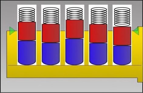
Fig. 1: Cylinder at rest.
The components you can see are:
Section B: How the key works
When we insert the correct key, the pin stacks will be lifted to their correct heights. The split between the key pins and drivers rests exactly at the shear line, and the plug is free to rotate. Please excuse the absence of a key in the following pictures, the diagrams aren't to scale and it was hard to draw a key without it looking rubbish.
So here is the correct key:
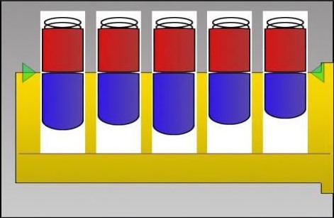
Fig. 2: Correct key inserted.
And here's an example of an incorrect key. As you can see, the shear line is still blocked because the pin stacks are misaligned:
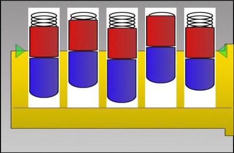
Fig. 3: Incorrect key inserted.
Even if only one pin is partially blocking the shear line, it's enough to stop the plug from turning. So how does picking work? Well, it all boils down to machining tolerances. Read on...
Section C: Tolerances and the binding defect
As you know, the key aligns all the pin stacks to their correct heights simultaneously. You'd think that without the key, this just can't be done and you'd be right. While possible, the chances of doing so would be extremely slim. But we can manipulate the pins individually, and this is made possible thanks to tolerances. Even with all our technology, it's physically impossible to make all the components exactly the same dimensions and this is what causes the binding defect.
When we apply a turning pressure to the plug, only one of the pins will be binding against the inside of its chamber. If everything was perfectly machined, then all of them would bind simultaneously, and picking with basic hand tools would be impossible. But in reality, this just isn't the case. The pin chambers are different diameters, they're not perfectly circular, and they're misaligned. The pins are all different as well, not identical in size or shape like you might think. The differences can't be seen with the naked eye unless the lock is very poorly made, but these defects are all present in even the highest quality locks, and this is what makes picking possible.
Below is an exaggerated example. To keep the head scratching to a minimum, the pin chambers are all the same size and everything is the same shape, chambers are perfectly aligned etc. the only variable here is the diameter of the pins. It's nowhere near this simple, but it's the easiest way to explain:
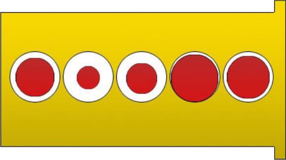
Fig. 4: Tolerances exagerrated & simplified.
In this lock, if we were to apply tension in either direction, pin 2 (looking right to left, where the key enters) would bind first because it's the biggest. It's physically impossible for any of the others to bind at this point, anyone can understand this. Pin 2 is blocking the plug from rotating, but the rest aren't making any contact with their chamber walls whatsoever. We would feel pin 2 binding, whereas the others would just spring up and down without any resistance. More on this shortly.
When we apply tension and lift this pin, once it reaches the shear line, three very important things will happen:
Fig. 5: Small ledge created by plug rotation.
The driver stays trapped above the plug, on that little ledge just to the side of the chamber, and the key pin drops back down. Now the pin stack in chamber 1 is binding, we lift that stack until the pins shear, and this same process continues until the lock opens. In this example, the binding order would be 2-1-5-3-4. And once 4 sets, the plug would rotate freely and open the lock. The binding order is completely random by the way, so don't go trying to pick every lock in this specific order. Even in 2 identical locks with the same key, the binding order will be completely different.
That covers the principles of binding and how pins stay set, so now you'll be able to understand all that funk you're feeling when you start to pick your first lock. Like I said, the tolerances are actually a mixed variety of imperfections working together and are much smaller than I've depicted — but generally speaking, the binding pin is pretty easy to identify. Higher quality machining means tighter tolerances, which makes it harder to tell (since multiple pins will be binding at once), but you'll still be able to tell which is binding more than the others. Don't give this too much thought, it all just comes down to practice and we'll be examining this in all its wonderful detail in just a moment.
I know you're dying to get started, so let's take a quick look at the different pin states and move on.
Section D: Pin states
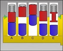
Fig. 6: Pin states.
From left to right:
OK. Now we can go.