Require the consignee to advise the consignor of any shipment not received more than 48 hours after the estimated time of arrival furnished by the consignor or the transshipping activity. Upon receipt of such notice, the consignor will immediately trace the shipment. If there is evidence that the classified material was subjected to compromise, the procedures set forth in AR 380-5, Chapter 10 for reporting compromises will apply.
z
Packaging material must be strong and durable enough to provide security protection while in transit, to keep items from breaking out of the container, and to help detect any tampering with the container. The wrappings must conceal all classified characteristics.
z
Use closed and locked vehicles, compartments, or cars for shipment of classified material except when the appropriate authority authorizes another method.
z
When classified material is transported, it will not be stored in any detachable storage compartment such as automobile trailers, luggage racks, aircraft travel pods, or drop tanks.
z
When transporting classified material across international borders, arrangements must be made to ensure that customs, border, or other inspectors (either US or foreign) do not open the material.
z
Place a serial-numbered seal on doors of containers, vehicles, or compartments that contain classified or protected cargo. The serial number must be entered on the shipment unit packing list and on all shipping documents.
z
The unit authorizing the transport of the classified equipment must notify the ITO/MCT and appropriate carrier in advance.
z
Shipping classified material by rail may require commanders to provide guards or escorts.
I-10. When traveling by motor convoy, escorts must ensure constant surveillance of classified material.
Classified material must stay within the escort’s personal possession and observation at all times. Larger pieces of secret shipments, such as missiles, may require outside storage. If so, take special protective measures to include constant and continuous surveillance by at least one or more escorts in the area.
SENSITIVE MATERIAL
I-11. Sensitive material is cargo that could threaten public safety if compromised. Sensitive cargo must be properly secured and identified to port personnel so sufficient security can be provided. Do not identify security cargo on the outside of the shipping containers. Detailed instructions are included in DTR
4500.9R.
I-12. For sensitive cargo, units must adhere to the following:
z
Remove crew-served weapons from vehicles. Place them in containers that are sealed and secured with an approved device.
z
Ensure packaging material is strong and durable enough to provide security protection while in transit.
z
Secure containers, vehicles, or compartments with an appropriate locking device as directed by the installation security officer. Also, place a serial-numbered seal on the door. Enter the serial number on the shipment unit packing list.
z
Identify sensitive items in the commodity code on the unit’s OEL/UDL.
z
Eliminate indications of sensitive items from outside of the container, vehicle, or compartment that it contains sensitive items. Identify this fact on the unit’s OEL/UDL.
z
Provide guards or escorts when shipping sensitive material by rail.
CUSTOMER SUPPORT
I-13. For assistance determining and complying with DOD packaging requirements contact DLA, DOSO-DH, DSN 695-4788 or (804) 379-4788, FAX X3793. Additionally, a performance-oriented I-4
FM 3-35
21 April 2010
Special Cargo
database is available to assist with determining and selecting appropriate packaging materials. To obtain access contact DLA. Container loading diagrams for ammunition and explosive items can be obtained by contacting the US Army Defense Ammunition Center, 1C Tree Road, Building 35, ATTN: SJMAC-DET, McAlester, OK 74501-9053.
21 April 2010
FM 3-35
I-5
This page intentionally left blank.
Appendix J
Automatic Identification Technology
AIT is a suite of technologies that enables the automatic capture of source data and enhances the ability to identify, track, and document deploying and redeploying
forces, equipment, and personnel. Commanders face many challenges during
deployment, and one is maintaining visibility of forces. ITV is intended to provide
them with the information necessary to track forces from point of origin to final
destination. AIT provides timely and accurate ITV data when combined with web-
enabled AIS. Effective management of deployment operations can be enhanced with
AIT. This appendix outlines the structure and components of AIT and the
responsibilities of the participants to maintain visibility of forces during deployment.
SIGNIFICANCE OF AIT
J-1. AIT alone is not the solution for maintaining ITV throughout the deployment and redeployment process. The AIT suite of capabilities significantly improves the accuracy and speed of ITV when combined with automated information systems, re-engineered operational procedures and staff engaged in force tracking and reporting. These capabilities can provide detailed, accurate, and timely information about the location of personnel, unit equipment, and sustainment cargo as they move from fort to foxhole and back.
J-2. To produce an accurate force tracking picture for the commander, an AIT network of trained personnel and equipment must be in place at each node of the deployment pipeline to collect and report the data. Moreover, established operational procedures must outline the process for the network to capture, report, and transfer the source data necessary to access the resulting force tracking data.
J-3. The resources of G1, G3, and G4 are brought together to build the force tracking network. The G1
has the responsibility to establish the procedures for collecting personnel data; the G3 establishes the readiness standards and the procedures for reporting force closure; and the G4 has the responsibility to provide AIT devices at appropriate locations to collect deployment movement data. The interrogator and transponder devices capture and report data as the equipment arrives and departs each node when RFID
tags or military shipping labels are interrogated or scanned. The data is passed at preset intervals (usually one hour) to a local automated information system and then to web-enabled ITV servers. Personnel data is collected through the use of smart cards that are scanned as personnel arrive and depart each location. This information will also be passed to the local automated information system and then to the appropriate web-enabled AIS.
CONFIGURATION
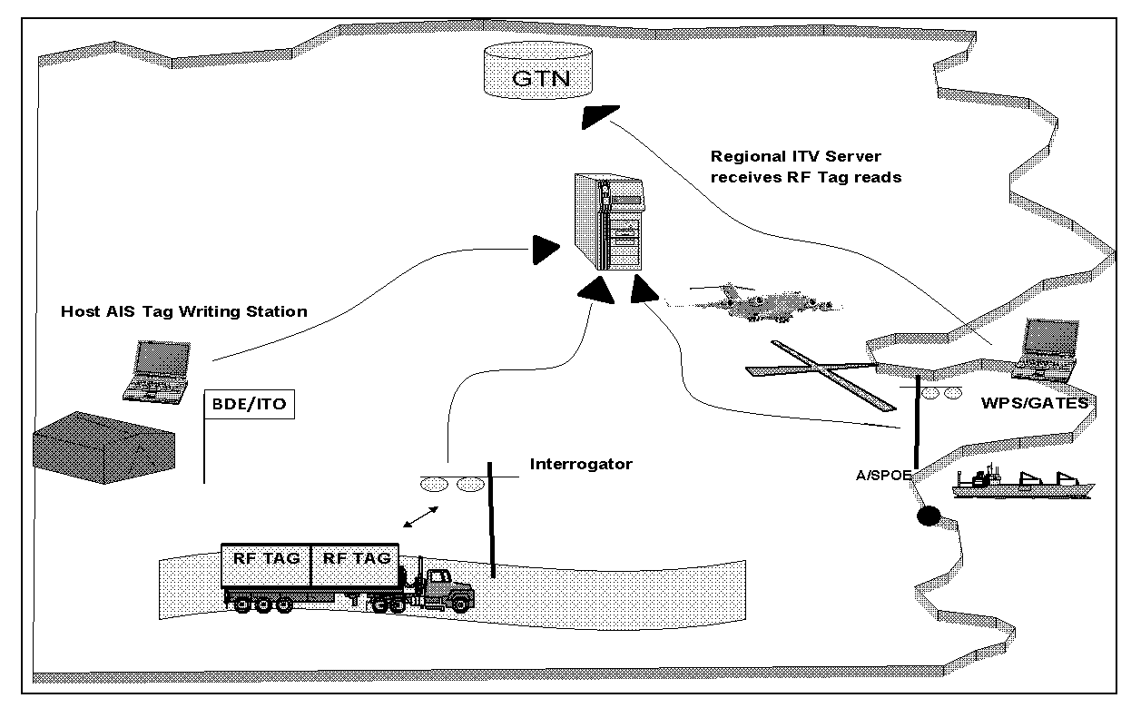
J-4. Radio frequency identification combines the features of a portable data collection device, a two-way radio, interrogator and transponder. RF tags contain information that can range from a permanent identification number to item level commodity data. Information can be written to tags using a fixed interrogator, a tag docking station, or hand held interrogator (HHI). After the initial data is written to the RFID tag, the data is passed from the host AIS to the regional ITV server. Once the tag is attached to a piece of equipment, pallet, or container and passes through the system, the interrogator sends out a RF
signal that "wakes up" the tag. The tag then transmits information back to the interrogator. The interrogator communicates with a host computer which, in turn, passes the data to the appropriate CONUS/regional ITV server updating the status (Figure J-1).
21 April 2010
FM 3-35
J-1
Appendix J
Figure J-1. RFID/ITV data collection
J-5. The active RF tag is the key to providing inside-the-box content visibility. Unlike a barcode, the RFID tag transmits the information wirelessly without human intervention. An RFID reader/interrogator reads and writes data to and from the tag. A Soldier with an interrogator can view the contents of the container/pallet/vehicle without having to open or unload them. This hands-off capability is what sets RF
tags apart from other AIT devices that require some form of intervention to capture the asset data.
STORAGE DEVICES
J-6. The Army will deploy in a joint environment, and there are numerous AIT devices available within DOD and the Army to support deployment missions. These devices capture and report arrivals and departures to GTN. AIT data storage devices contain or store essential transportation and supply data. It is printed or created and is then attached to equipment. The information on the AIT data storage device is also present in AIS and is passed to web-enabled AIS that provide global asset/movement visibility. The Army currently uses MSLs, RFID tags and other assorted media as data storage devices for deployment.
Data storage devices include but are not limited to the following:
z
Linear Bar Code: A bar code can be thought of as a key in the form of a unique number that is coded in a series of black and white bars. The key allows you to enter a database that contains detailed information about the item represented by the key. Linear bar codes are limited in the amount of information they contain and are one-dimensional.
z
2D Bar Code: 2D bar codes store data horizontally and vertically and therefore have a larger storage capacity. MSLs use this format.
z
RF Tags: Radio frequency identification combines the features of a portable data collection device and a two-way radio. RF tags contain information that can range from a permanent identification number to item level commodity data. Information can be written to tags using a fixed interrogator, a tag docking station, or HHI.
J-2
FM 3-35
21 April 2010

Automatic Identification Technology
COMPONENTS
J-7. Basic components of AIT used to support unit deployments and redeployments are shown in Figures J-2 through J-5.
Figure J-2. AIT/RFID tags
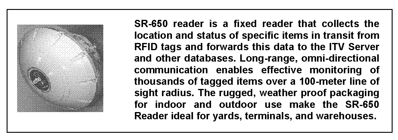
Figure J-3. Fixed interrogator
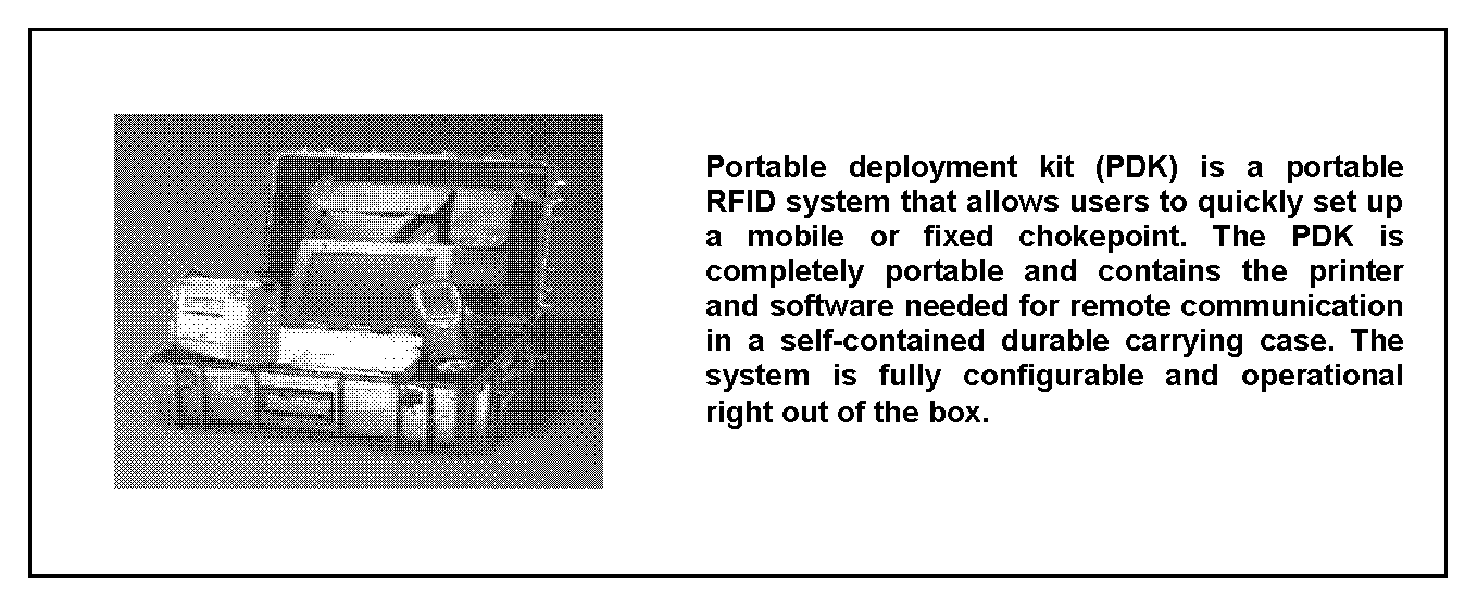
Figure J-4. Portable deployment kit (PDK)
21 April 2010
FM 3-35
J-3
Appendix J
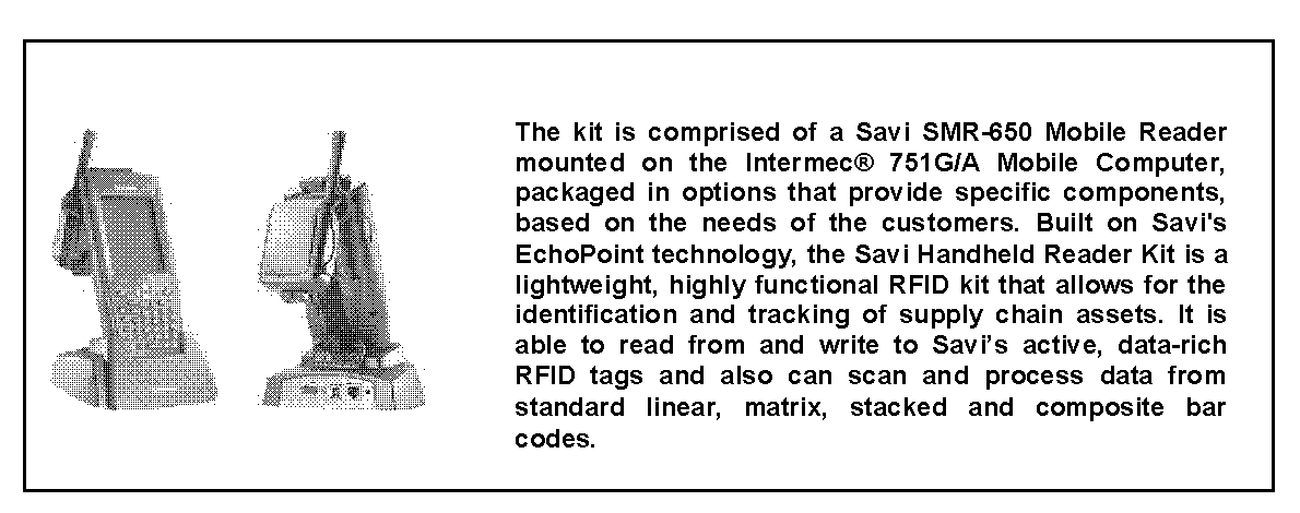
Figure J-5. Handheld interrogator/reader
APPLICATIONS
INSTALLATIONS
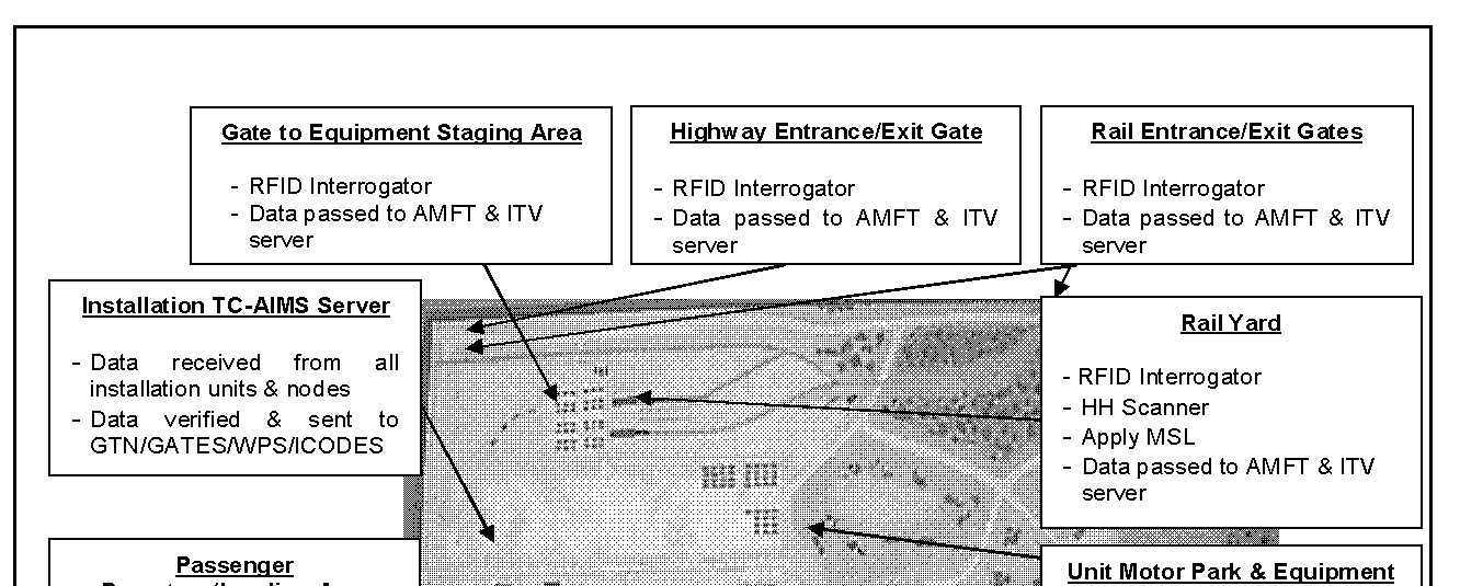
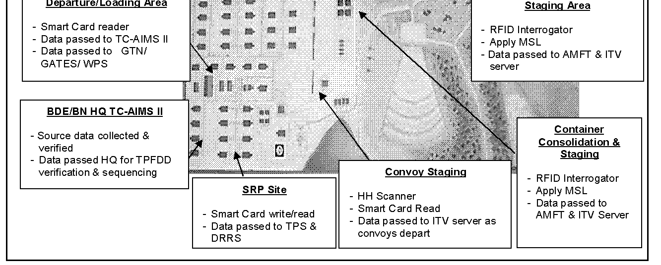
J-8. A plan must be in place to create a local area network (LAN) that links each installation deployment node and all headquarters possessing TC-AIMS II and associated AIS. This network must be capable of operating 24 hours a day to support the deployment flow throughout the operation. A direct dial-up capability should be considered if a LAN is not available. In addition to linking all the TC-AIMS II and global combat support systems to this LAN, procedures must be in place to link AIT interrogators/readers that are supporting service AIS. These procedures allow for the automatic capture and transfer of movement data with limited human intervention. Figure J-6 depicts a notional installation AIT laydown.
J-4
FM 3-35
21 April 2010
Automatic Identification Technology
Figure J-6. Notional installation AIT laydown
J-9. Installations have a responsibility to help build a deployment plan for all units and equipment deploying from their location. The information used to develop the deployment plan comes from UDLs and passenger manifests. As movements occur, installations take the data that is rolled up in TC-AIMS II and transmits to GTN. The installation will be the first location where AIT data storage devices are scanned/interrogated and verified against data resident in service AIS. Closely checking the AIT data storage devices of the first deploying units provide the installation and deploying commanders a benchmark to measure how well units are conducting their AIT and mission. Follow-on deploying units can be informed of AIT problems and correct deficiencies before departing the installation.
J-10. The installation must examine the deployment process and determine the best location to install fixed and temporary AIT interrogators and readers. Possible locations for the installation of interrogators include entry and exit gates, convoy marshalling/staging areas, loading areas, container consolidation points, ammunition supply points, and vehicle scales. Soldier readiness processing sites and passenger holding/staging areas are also possible locations for interrogators and CAC card readers.
21 April 2010
FM 3-35
J-5


Appendix J
Figure J-7. Notional APOE/APOD AIT laydown
J-11. installations must plan for the use of HHIs to scan labels attached to equipment. Data capture from the scanned labels is then used to create new RFID tags to restore ITV.
AERIAL PORT
J-12. The arrival and departure of all unit equipment, personnel, and sustainment air cargo transiting the aerial terminals must be captured in service AIS and reported to GTN. Detailed planning and coordination should be performed in advance of operations detailing AIT requirements at the aerial terminals. The A/DACG will coordinate with the USAF for specific AIT requirements, infrastructure, and support in order to collect and report data on Army unit and equipment arrivals. The A/DACG will then communicate with deploying units the ITV plan for providing and collecting in-transit visibility data of their unit equipment and cargo.
Processing Passengers
J-13. Passengers moving through an APOE can expect to process through a marshalling area and a passenger holding area. Marshalling areas may be located at the home station, the APOE, or both depending on the situation. If the marshalling area was at home station and this is the first time data has been collected on the arrival of passengers at the airfield, procedures must be established to pass this data to GTN. While in the marshalling area, the unit verifies personnel manifests and ensures that all Soldiers have a current CAC card. The Army support element controlling the marshalling area will scan the arriving Soldier’s CAC card for internal accountability and for ITV reporting requirements. Following the correction of any CAC card deficiencies, units should rescan all CAC cards and match the data against the manifest as Soldiers depart the marshalling area for the passenger holding area.
J-6
FM 3-35
21 April 2010
Automatic Identification Technology
J-14. Normally, a passenger holding area will be established near the APOE that is jointly operated by the Army and USAF. As Soldiers arrive, the Army support element will scan CAC cards and verify the information against the unit manifest. The Army support element will assist in making any final manifest corrections and when notified, pass control of deploying Soldiers to the USAF along with an electronic copy of the personnel manifest. The USAF element will load this electronic data into GATES and pass departure data to GTN.
Processing Unit Equipment
J-15. Unit equipment proceeds through four areas on or near the APOE when processing for deployment: by air-marshalling area, by alert holding area, by call-forward area, and by ready line/loading area. There are potential overlapping responsibilities at these locations, and prior coordination is essential to minimizing such occurrences.
J-16. An equipment marshalling area can be located on the installation, in the vicinity of the airfield, or both depending on the deployment situation. The marshalling area is normally operated by the supporting installation. A plan should be in place that clearly defines AIT responsibilities at the APOE. FORSCOM
has a memorandum of understanding in place with the USAF addressing responsibilities at CONUS
locations. While in the marshalling area and with the assistance of the support element, deploying units are responsible for preparing their equipment for shipment, to include the proper AIT tagging and marking.
The Army support element will capture the arrival and departure data and report it to GTN if the marshalling area is on the airfield. Any problems or deficiencies found with AIT data storage devices should be corrected by the unit before moving to the call-forward area. After preparing their equipment for air movement, units will arrange vehicles and equipment in chalk order before movement to the alert holding area.
J-17. The alert holding area is normally on the airfield and controlled by the DACG where they will coordinate operations between the unit and the USAF. In the alert holding area, the DACG scans the MSLs of arriving and departing equipment for internal accountability and control purposes. If the alert holding area is the first place where Army equipment is accounted for on the airfield, this arrival data must be passed on to GTN. Any deficiencies should be corrected by the unit before the equipment is moved to the call-forward area. This is the last place where Army AIT deficiencies can be corrected prior to air movement.
J-18. The call-forward area of the airfield is under the control of the DACG. It’s where the joint inspection of equipment is conducted and manifests are reviewed for accuracy. The unit and the USAF conduct a joint inspection of all equipment to ensure it is properly prepared for airlift. With assistance of the DACG, the unit corrects all deficiencies found during the joint inspection.
J-19. The ready line/loading area is under the operational control of the USAF. The DACG passes control of Army unit equipment to the USAF at the ready line. The USAF ensures that the aircraft is loaded properly and sends aircraft departure and ITV data to GTN via GATES.
SEAPORT
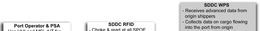
J-20. The SDDC is the military port manager for all common-user water terminals and is responsible for SPOE operations (Figure J-8). Also operating in the port complex will be MSC, the PSA, and the unit.
Other possible operators at the port are civilian port managers and operators as well as the Army port operators and movement control team. SDDC coordinates operations between Army units and MSC and all activities with the civilian port authorities and operators.
21 April 2010
FM 3-35
J-7


Appendix J
Figure J-8. Notional SPOE/SPOD AIT laydown
J-21. SDDC is responsible for installing, operating, and maintaining the AIT network within the port complex. The PSA will use AIT to capture the movement of unit equipment through the port complex and to locate tagged unit equipment in the port area. PSAs constituted from TOE units will normally have organic AIT equipment, while ad hoc PSAs must rely on the supporting installations for the necessary AIT
resources.
Processing Unit Equipment
J-22. Unit equipment transiting a SPOE will generally pass through a marshalling area (normally outside the port) and a staging area before vessel loading. Depending on the amount of unit equipment involved, a marshalling area may not be established. The purpose of a marshalling area is to provide a location near the port complex to assemble unit equipment and make final preparations before entering the port.
J-23. Fixed AIT interrogators/readers can be installed at port entrance and exit gates, marshalling and staging areas, container consolidation points, and off/on load sites established to assist in data capture and internal port control. Captured arrival/departure data will be passed to WPS and sent to the GTN.
J-24. The staging area is the final location where equipment is assembled prior to loading the vessel.
Equipment is usually lined up by piece type or in the order it is to be moved onto the ship. SDDC will control all equipment departing the staging area for loading on vessels. Normally, the equipment is scanned at the final stowage location and the data is passed to WPS and is sent to GTN in the form of a final ships manifest.
J-8
FM 3-35
21 April 2010
Automatic Identification Technology
J-25. Port managers and operators will rely on hand held scanners to collect data from the MSLs and transfer the data into WPS. The data will be used for internal port control of the equipment, to develop the final stow location of unit equipment aboard the vessel, and to prepare the final ships manifest.
J-26. Care must be used when establishing the location of fixed RFID interrogators. The interrogator must be properly positioned to capture the arrival and departure of all unit equipment moving past its location, while at the same time, not interrogating tags already staged. An interrogator located too close to RFID
tags can query tags constantly and drain the tag batteries before the equipment is loaded.
Processing Passengers
J-27. A final SPOE AIT consideration is capturing the movement of personnel by ship. This can be accomplished by means of support agreements with SDDC, the Navy, or the use of organic unit AIT
equipment. Planners must identify the requirement as early as possible to ensure the system is in place to capture the data and transmit it to GTN.
RESPONSIBILIES
INSTALLATIONS
J-28. Installations are the mainstay of deployment operations, and there are numerous AIT functions performed by the installation activities that support and enhance deployment. Plans must be in place defining the respective AIT responsibilities to ensure that the most accurate data is entered into the AIS in a timely fashion. The foremost installation AIT tasks are—
z
Install and maintain AIT interrogators/readers.
z
Ensure data is accurate and forwarded within established time standards.
z
Confirm units have properly labeled/tagged their equipment and Soldiers have a current CAC
card.
z
Implement and maintain an installation business process that is supportive of operations throughout the system.
J-29. Other AIT issues to be considered in developing an installation plan include location of source data, quality control procedures, funding, support, accountability, and training.
UNITS
J-30. Accurate and complete initial source data must be entered in automated information systems before the deployment begins. For units, this means ensuring the unit equipment list in TC-AIMS II is accurate and up-to-date. In addition, procedures must be followed to ensure MSLs and RF tags are produced using the data in TC-AIMS II. Once produced, these AIT data storage devices must be attached to the proper piece of equipment and then scanned/interrogated to verify readability and accuracy. Commanders must ensure that every Soldier has an updated CAC card after completing the Soldier readiness process. For passenger movements, these cards will be used to manifest and account for Soldiers at arrival and departure locations throughout the deployment operation.
J-31. The UMO will use TC-AIMS II to create an accurate UDL that identifies all items to be tagged and labeled for deployment. The Brigade Mobility Officer and UMC will review the file. When the review process is complete, the file will be passed to JFRG II and then to JOPES.
J-32. One-time capture and passing of source data between AISs is the preferred method for meeting ITV
and force tracking timeliness standards. All deployment nodes use this data to update their automated information systems for ITV.
THEATER
J-33. The Army's use of AIT in a deployment operation will be based on the supported combatant commander's movement control and RSOI plan. The plans will be designed to enable the in-theater 21 April 2010
FM 3-35
J-9


Appendix J
distribution systems to meet force closure requirements. ITV plans will vary based on the geographic area of operation, mission requirements, and the supporting transportation and communication infrastructures.
The ASCC G-4 in coordination with the G-3 develops the Army's portion of the theater ITV and RSOI plans. The G-4’s input to these plans includes the use of AIT and enables executing agencies to properly plan their local AIT requirements.
J-34. Once source data is verified, plans