by laying a straightedge across the rut, measuring its depth, then using
measurements taken along the length of the rut to compute its mean depth in
inches.
Name of Distress:
Shoving.
Description:
Shoving is a permanent, longitudinal displacement of a localized area of the pavement surface caused by traffic loading. When traffic pushes against the pavement, it produces a short, abrupt wave in the pavement surface. This
distress normally occurs only in unstable liquid asphalt mix (cutback or
emulsion) pavements.
Shoves also occur where asphalt pavements abut PCC pavements; the PCC
pavements increase in length and push the asphalt pavement, causing the
shoving.
Severity Levels:
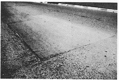
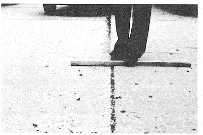
L-Shove causes low-severity ride quality (fig B-60).
B-20
TM 5-623
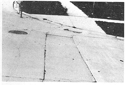
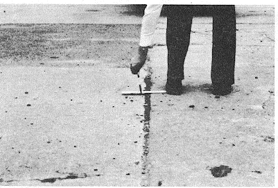
M-Shove causes medium-severity ride quality (fig B-61).
Figure B-60. Low-severity shoving.
Figure B-61. Medium-severity shoving approaching high
severity.
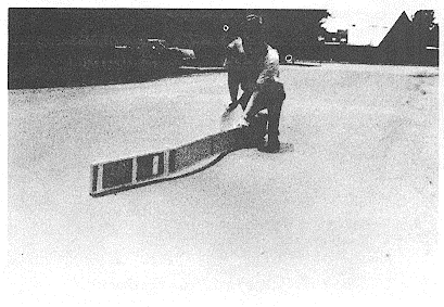
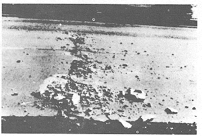
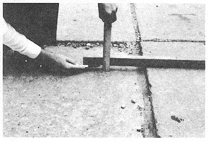
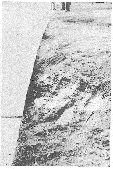
H-Shove causes high-severity ride quality (fig B-62).
How to Measure:
Shoves are measured in square feet of surface area.
Shoves occurring in patches are considered in rating the patch, not as a separate distress.
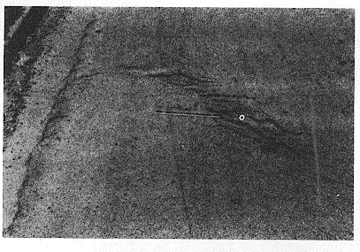
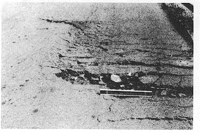
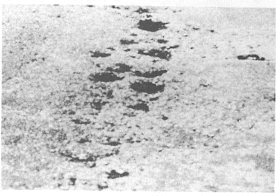
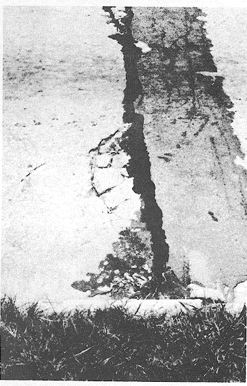
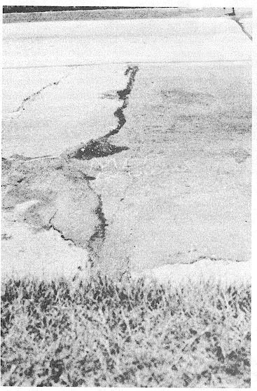
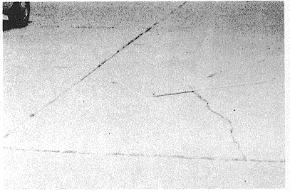
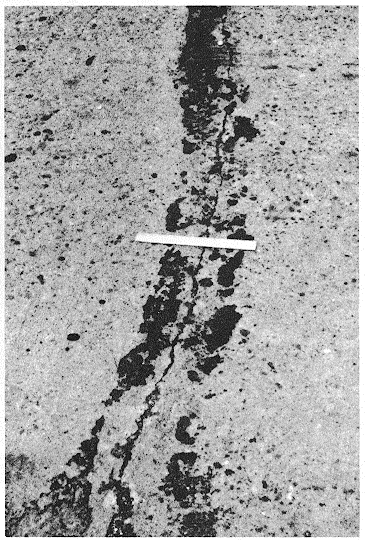
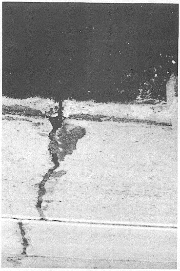
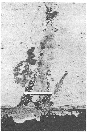
Name of Distress:
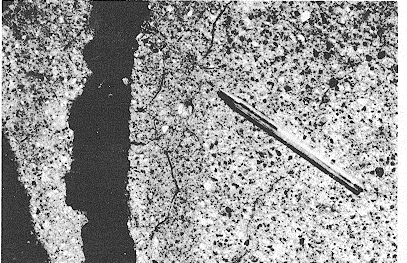
Slippage Cracking.
Description:
Slippage cracks are crescent or half-moon-shaped cracks having two ends
pointing away from the direction of traffic. They are produced when breaking or turning wheels cause the pavement surface to slide or deform. This
distress usually occurs when there is a low-strength surface mix or a poor
bond between the surface and the next layer of the pavement structure.
Severity Levels:
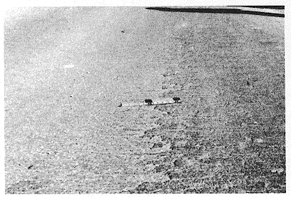
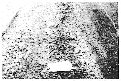
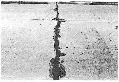
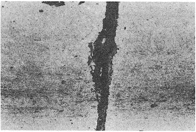
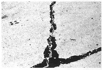
L-Average crack width is less than % inch (fig B-63).
Figure B-62. High-severity shoving.
Figure B-63. Low-severity slippage cracking.
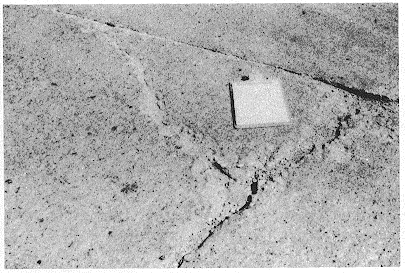
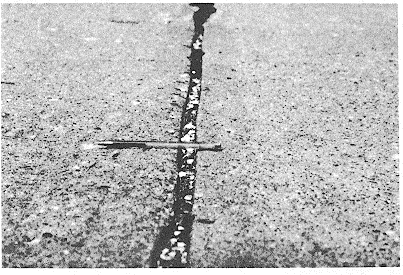
M-One of the following conditions exists (fig B-64):
1.
Average crack width is between X and 1 inches.
2.
The area around the crack is broken into tight-fitting pieces.
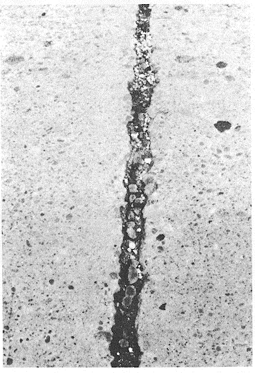
H-One of the following conditions exists (fig B-65):
B-21
TM 5-623
Figure B-65. High-severity slippage cracking.
Figure B-64. Medium-severity slippage cracking.
1.
The average crack width is greater than 1I inches.
2.
The area around the crack is broken into easily removed pieces.
How to Measure:
The area associated with a given slippage crack is measured in square feet and rated according to the highest level severity in the area.
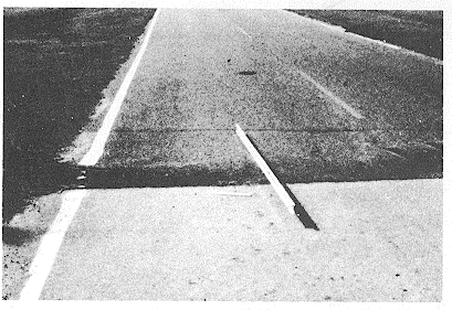
Name of Distress:
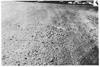
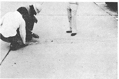
Swell.
Description:
Swell is characterized by an upward bulge in the pavement’s surface-a long,
gradual wave of more than 10 feet long. Swelling can be accompanied by
surface cracking. This distress is usually caused by frost action in the
subgrade or by swelling soil.
Severity Levels:
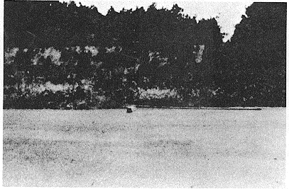
L-Swell causes low-severity ride quality. Low-severity swells are not always easy to see, but can be detected by driving at the speed limit over the pavement
section. An upward acceleration will occur at the swell if it is present. (See
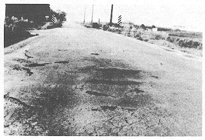
fig B-66.) M-Swell causes medium-severity ride quality. (See fig B-66.) H-
Swell causes high-severity ride quality. (See fig B-66.)
Figure B-66. Example swell; severity level is based on ride quality criteria.
How to Measure:
The surface of the swell is measured in square feet.
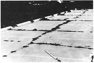
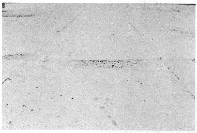
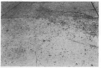
Name of Distress:
Weathering and Raveling.
B-22
TM 5623
Description:
Weathering and raveling are the wearing away of the pavement surface caused
by the loss of asphalt or tar binder and dislodged aggregate particles. These distresses indicate that either the asphalt binder has hardened appreciably or that a poor-quality mixture is present. In addition, raveling may be caused by certain types of traffic, e.g., tracked vehicles.
Severity Levels:
L-Aggregate or binder has started to wear away. In some areas, the surface is
starting to pit (figs B-67 and B-68).
Figure B-67. Low-severity weathering and raveling.
Figure B-68. Low-severity weathering and raveling
caused by tracked vehicles.
M-Aggregate and/or binder has worn away. The surface texture is moderately
rough and pitted (figs B-69 and B-70).
Figure B-69. Medium-severity weathering and raveling.
Figure B-70. Medium-severity weathering and raveling.
H-Aggregate and/or binder has been considerably worn away. The surface
texture is very rough and severely pitted. The pitted areas are less than 4
inches in diameter and less than 3 inch deep; pitted areas larger than this are
counted as potholes (fig B-71).
B-23
TM 5-623
How to Measure:
Weathering and raveling are measured in square feet of surface area.
ALPHABETICAL LISTING OF DISTRESS TYPES-JOINTED CONCRETE PAVEMENTS
Name of Distress:
Blow-up/Buckling.
Description:
Blow-ups or buckles occur in hot weather, usually at a transverse crack or joint that is not wide enough to permit slab expansion. The insufficient width is usually caused by infiltration of incompressible materials into the joint space.
When expansion cannot relieve enough pressure, a localized upward
movement of the slab edges (buckling) or shattering will occur in the vicinity of the joint. Blow-ups can also occur at utility cuts and drainage inlets.
Severity Levels:
L-Buckling or shattering causes low-severity ride quality (fig B-72).
Figure B-71. High-severity weathering and raveling.
Figure B-72. Low-severity blow-up/buckling.
M-Buckling or shattering causes medium-severity ride quality (figs B-73 and B-
B-24
TM 5-623
Figure B-74. Medium-severity blow-up/buckling.
Figure B-73. Medium-severity blow-up/buckling.
H-Buckling or shattering causes high-severity ride quality (fig B-75).
Figure B-75. High-severity blow-up/buckling approach inoperative conditions.
How to Count:
At a crack, a blow-up is counted as being in one slab. However, if the blowup occurs at a joint and affects two slabs, the distress should be recorded as
occurring in two slabs. When a blow-up renders the pavement inoperable, it
should be repaired immediately.
Name of Distress:
Corner Break.
B-25
TM 5-623
Description:
A corner break is a crack that intersects the joints at a distance less than or equal to one-half the slab length on both sides, measured from the corner of the
slab. For example, a slab with dimensions of 12 by 20 feet that has a crack 5
feet on one side and 12 feet on the other side is not considered a corner
break; it is a diagonal crack. However, a crack that intersects 4 feet on one side and 8 feet on the other is considered a corner break. A corner break
differs from a corner spall in that the crack extends vertically through the entire slab thickness, while a corner spall intersects the joint at an angle.
Load repetition combined with loss of support and curling stresses usually
causes corner breaks.
Severity Levels:
L*--Break is defined by a low-severity crack and the area between the break and
the joints is not cracked or may be lightly cracked (figs B-76 and B-77).
Figure B-76. Low-severity corner break.
Figure B-77. Low-severity corner break.
M*-Break is defined by medium-severity crack and/or the area between the break
and the joint is mediumly cracked (fig B-78).
H*--Break is defined by a high-severity crack and/or the area between the break
and the joints is highly cracked (fig B-79).
*See linear cracking for a definition of low-, medium, and high-severity cracks.
B-26
TM 5-623
Figure B-78. Medium-severity corner break. Defined by
Figure B-79. High-severity corner break.
a medium-severity crack.
How to Count:
Distressed slab is recorded as one slab if it::
1.
Contains a single corner break.
2.
Contains more than one break of a particular severity.
3.
Contains two or more breaks of different severities.
For two or more breaks, the highest level of severity should be recorded. For example, a slab containing both low and medium-severity corner breaks
should be counted as one slab with a medium corner break.
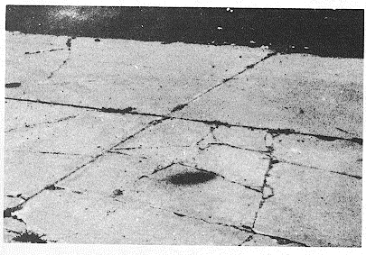
Name of Distress:
Divided Slab.
Description:
Slab is divided by cracks into four or more pieces due to overloading and/or inadequate support. If all pieces or cracks are contained within a corner
break, the distress is categorized as a severe corner break.
Severity Levels:
Severity of
Number of pieces in cracked slab
majority of
cracks
4 to 5
6 to 8
More than 8
L
L
L
M
M
M
M
H
H
M
H
H
See figures B-80 through B-84.
Figure B-80. Low-severity divided slab. Majority of
Figure B-81. Medium-severity divided slab.
cracks are low severity access than 1/2 inch wide and no
faulting).
B-27
TM 5-623
Figure B-82. High-severity divided slab caused by high-
Figure B-83. High-severity divided slab.
severity cracks.
Figure B-84. High-severity divided slab.
How to Count:
If the slab is medium or high-severity, no other distress is counted.
Name of Distress:
Durability ("D") Cracking.
Description:
"D" cracking is caused by freeze-thaw expansion of the large aggregate which, over time, gradually breaks down the concrete. This distress usually appears as a pattern of cracks running parallel and close to a joint or linear crack.
Since the concrete becomes saturated near joints and cracks, a dark-colored
deposit can usually be found around fine "D" cracks. This type of distress may eventually lead to disintegration of the entire slab.
Severity Levels:
L-"D" cracks cover less than 15 percent of slab area. Most of the cracks are
tight, but a few pieces may have popped out (figs B-85 and B-86).
B-28
TM 5-623
Figure B-86. Low-severity durability cracking.
Figure B-85. Low-severity durability cracking.
M-One of the following conditions exists (fig B-87):
Figure B-87. Medium-severity durability cracking.
1.
"D" cracks cover less than 15 percent of the area and most of the pieces have popped out or can be easily removed.
2.
"D" cracks cover more than 15 percent of the area. Most of the cracks are tight, but a few pieces may have popped our or can be easily removed.
H-"D" cracks cover more than 15 percent of the area and most of the pieces have
popped out or can be easily removed (see figs B-88 and B-89).
B-29
TM 5-623
Figure B-88. High-severity durability cracking.
Figure B-89. High-severity durability cracking.
How to Count:
When the distress is located and rated at one severity, it is counted as one slab.
If more than one severity level exists, the slab is counted as having the higher severity distress. For example, if low and medium "D" cracking are on the same slab, the slab is counted as having medium-severity cracking only.
Name of Distress:
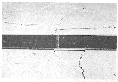
Faulting.
Description:
Faulting is the difference in elevation across a joint. Some of the common
causes of faulting are:
1.
Settlement because of soft foundation.
2.
Pumping or eroding of materiel from under the slab.
3.
Curling of the slab edges due to temperature and moisture changes.
Severity Levels:
Severity levels are defined by the difference in elevation across the crack or joint.
Severity level
Difference in elevation
L
1/8 to 3/8 inch
M
3/8 to 3/4 inch
H
> 3/4 inch
See figures B-90 through B-93.
Figure B-90. Low-severity faulting.
Figure B-91. Medium-severity faulting.
B-30

TM 5-623
Figure B-92. Medium-severity faulting.
Figure B-93. High-severity faulting.
How to Count:
Faulting across a joint is counted as one slab. Only affected slabs are counted.
Faults across a crack are not counted as distress, but are considered when
defining crack severity.
Name of Distress:
Joint Seal Damage.
Description:
Joint seal damage is any condition which enables soil or rocks to accumulate in the joints or allows significant water infiltration. Accumulation of
incompressible materials prevents the slabs from expanding and may result
in buckling, shattering, or spalling. A pliable joint filler bonded to the edges of the slabs protects the joints from material accumulation and prevents water
from seeping down and softening the foundation supporting the slab.
Typical types of joint seal damage are:
1.
Stripping of joint sealant.
2.
Extrusion of joint sealant.
3.
Weed growth.
4.
Hardening of the filler (oxidation).
5.
Loss of bond to the slab edges.
6.
Lack or absence of sealant in the joint.
Severity Levels:
L-Joint sealant is in generally good condition throughout the section. Sealant is
performing well, with only minor damage (see above) (fig B-94).
M-Joint sealant is in generally fair condition over the entire section, with one more of the above types of damage occurring to a moderate degree. Sealant
needs replacement within 2 years (fig B-95).
Figure B-94. Low-severity joint seal damage.
Figure B-95. Medium-severity joint seal damage.
B-31
TM 5-623
H-Joint sealant is in generally poor condition over the entire section, with one or more of the above types of damage occurring to a severe degree. Sealant
needs immediate replacement (figs B-96 and B-97).
Figure B-96. High-severity joint seal damage.
Figure B-97. High-severity joint seal damage.
How to Count:
Joint seal damage is not counted on a slab-by-slab basis, but rated based on the overall condition of the sealant over the entire area.
Name of Distress:
Lane/Shoulder Drop Off.
Description:
Lane/shoulder drop off is the difference between the settlement or erosion of the shoulder and the pavement travel-lane edge. The elevation difference can be a safety hazard; it can also cause increased water infiltration.
Severity Levels:
L-The difference between the pavement edge and shoulder is 1 to 2 inches (fig B-
M-The difference in elevation is 2 to 4 inches (fig B-99).
B-32
TM-5-623
Figure B-98. Low-severity lane/shoulder drop off.
Figure B-99. Medium-severity lane/shoulder drop off
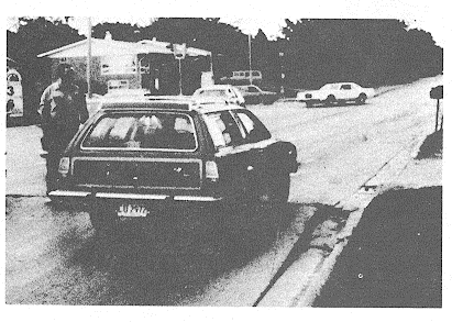
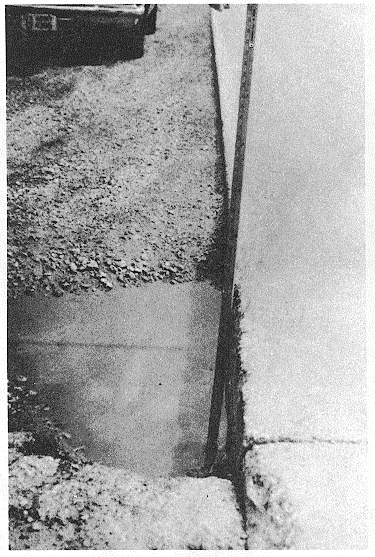
H-The difference in elevation is greater than 4 inches (fig B-100).
B-33
TM 5-623
Figure B-100. High-severity lane/shoulder drop off.
How to Count:
The mean lane/shoulder drop off is computed by averaging the maximum and
minimum drop along the slab. Each slab exhibiting distress is measured
separately and counted as one slab with the appropriate severity level.
Name of Distress:
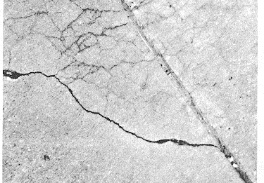
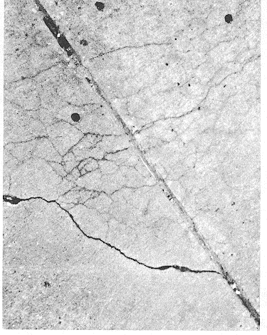
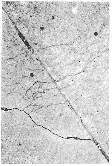
Linear Cracking (Longitudinal, Transverse, and Diagonal Cracks).
Description:
These cracks, which divide the slab into two or three pieces, are usually caused by a combination of repeated traffic loading, thermal gradient curling, and
repeated moisture loading. (Slabs divided into four or more pieces are
counted as Divided Slabs.) Low-severity cracks are usually related to warp or friction and are not considered major structural distresses. Medium or high-severity cracks are usually working cracks and are considered major
structural distresses (fig B-101 through B-106).
B-34
TM 5-623
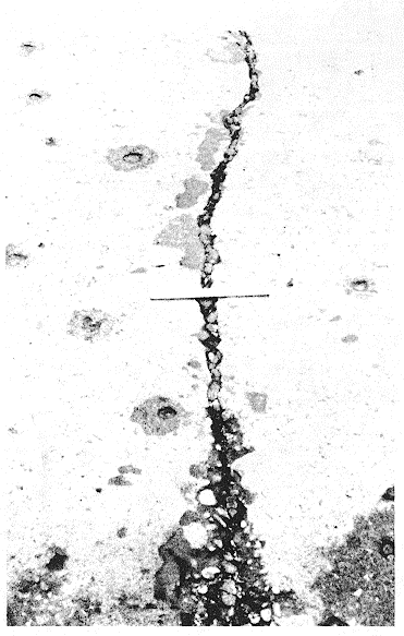
Figure B-101. Low-severity linear cracking in a
nonreinforced
concrete slab.
Figure B-102. Low-severity linear cracking in a
nonreinforced
concrete slab.
Figure B-103. Medium-severity linear cracking in a
reinforced
concrete slab.
B-35

TM 5-623
Figure B-104. Medium-severity linear cracking in a reinforced concrete slab.
Figure B-105. High-severity linear cracking in a nonreinforced concrete slab.
B-36
TM 5-623
Figure B-106. High-severity linear cracking in a nonreinforced concrete slab.
Hairline cracks that are only a few feet long and do not extend across the entire slab are counted as shrinkage cracks.
Severity Levels:
Nonreinforced Slabs: L-Nonfilled* cracks less than or equal to Y inch or filled cracks of any width with the filler in satisfactory condition. No faulting exists.
M-One of the following conditions exists:
1.
Nonfilled crack with a width between Y and 2 inches.
2.
Nonfilled crack of any width up to 2 inches with faulting of less than X inches.
3.
Filled crack of any width with faulting less than % inch.
H-One of the following conditions exists:
1.
Nonfilled crack with a width greater than 2 inches.
2.
Filled or nonfilled crack of any width with faulting greater than % inch.
Reinforced Slabs.
L-Nonfilled cracks with a width of Y8 to 1 inch; filled crack of any width with the filler in satisfactory condition. No faulting exists.
M-One of the following conditions exist:
1.
Nonfilled cracks with a width between 1 and 3 inches and no faulting.
2.
Nonfilled crack of any width up to 3 inches with up to v8 inch of faulting.
3.
Filled crack of any width with faulting less than % inch.
H-One of the following conditions exists:
1.
Nonfilled crack with width over 3 inches.
2.
Filled or nonfilled crack of any width with faulting over % inch.
*Filed cracks where filler is unsatisfactory are treated as nonfilled.
B-37