Chapter 3
Force Provider Module Equipment
SECTION I - INTRODUCTION TO FORCE PROVIDER MODULE EQUIPMENT
GENERAL INFORMATION
3-1. As previously stated, the Force Provider module is the basic building block for larger Force Provider systems. The major subsystems are rearranged to adapt to terrain, mission, local utility support, or area constraints. One module supports up to 550 Soldiers, however future plans call for the ability of the system to adapt to support independent 150 man modules.
3-2. The module consists of existing and new sustainment equipment. It is built around specific subsystems, some of which are found only in a Force Provider module (containerized latrine, the all- electric kitchen, and the containerized batch laundry system). Not all modules are identical. Throughout the production cycle modifications and improvements have been, and continue to be made. A notional layout of the 550 module is shown in Figure 3-1.
3-3. Aside from efficiency, a major factor in the design of the module was storage and ease of transportation. The system is packaged in triple containers (TRICONs). Each TRICON's outside dimensions are 8 by 8 by 6½ feet, and weigh up to 10,000 pounds fully loaded. Containerized latrines and showers, MWR equipment, and batch laundry subsystems are housed and shipped in 20-foot containers. Modules are classified as Army pre-positioned stock, available for deployment/placement by air, land or sea, from either depots or pre-positioned ships.
3-4. The Force Provider module supports eleven major functional areas which coincide with the module subsystems. In some cases, a subsystem may be located at more than one site, such as the latrine and shower systems, or may be large and dispersed, such as the gray water collection system. The major subsystems of a Force Provider module are:
• Billeting with environmental control units (ECU) for heating and cooling
• Administrative facility
• Morale, welfare, and recreation facility
• Containerized shower
• Containerized batch laundry
• Containerized latrine
• Food service subsystem (all electric)
• Bulk fuel storage and distribution system
• Potable water storage and distribution system
• Gray water collection system
• Power generation and illumination system (PDISE)
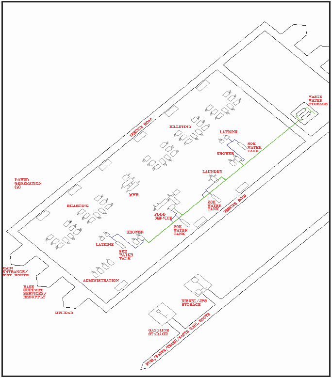
Figure 3·1. Force Provider Module Notional Layout
SECTION II - FORCE PROVIDER EQUIPMENT SUBSYSTEMS
TENT, EXTENDABLE, MODULAR, AND PERSONNEL (TEMPER)
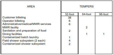
3-5. The heart of the Force Provider module is the TEMPER, although future plans call for it to be replaced by air-beam shelter systems. The TEMPER provides climate controlled billeting, supports facilities for customer/tenant functions, and is equipped with lights, convenience power outlets, fabric flooring, heating and air-conditioning, as well as vestibules and bump-through doors. Each billet TEMPER is equipped with bunk beds and footlockers, chairs and cleaning supplies. TEMPERs are constructed in 8- foot sections. A 32-foot TEMPER has four 8-foot sections, and requires 11 Soldiers to erect (supervisor and two Soldiers per arch). Table 3-1 shows TEMPER quantities in a typical Force Provider module. As the table illustrates, 96-foot TEMPER configurations may serve as large dining facilities, and 64-foot configurations may serve as smaller dining areas or MWR support facilities.
Table 3·1. TEMPERs in a Typical Force Provider Module
ADMINISTRATIVE SUBSYSTEM
3-6. The administrative subsystem provides facilities for administrative and Army Health Support. The six 32-foot TEMPERs in this section, which share a common area, are used for the following missions:
• Administrative. Provides space to control day-today operations of the module and includes tables and chairs.
• Army Health Support. Provides space for user unit or medical personnel and equipment to support a particular mission and includes tables, chairs, cots, and a first aid kit.
3-7. Available publications on the TEMPER and its auxiliary equipment are listed in the reference section located near the rear of this field manual.
MORALE, WELFARE AND RECREATION SUBSYSTEM
3-8. The Morale, Welfare and Recreation (MWR) Subsystem consists of two 64-foot TEMPERs, with environment control units (EeUs) to house MWR functions/services to support Force Provider operations. These services may include finance, mail handling, telephones, barber shop, recreational facility, personal services and a post exchange. Limited recreational equipment may be included, such as tennis tables, weights, and big-screen TV with VeR/DVD and satellite dish.
CONTAINERIZED SHOWER
3-9. The containerized shower houses 12 private shower stalls, with separate water controls for each stall. A containerized shower with four private shower stalls is being developed for future modules. A 32- foot TEMPER for shave stands and a changing area are included in the subsystem. Future plans call for incorporation of a shower water re-use system which promises to significantly reduce Force Provider water supply requirements. Available publications on the containerized shower are listed in the reference section located near the rear of this field manual.
CONTAINERIZED BATCH LAUNDRY
3-10. The containerized batch laundry subsystem consists of a 20-foot modified general cargo container and a TEMPER. See Figure 3-2. It houses two commercial-duty washers and dryers permanently mounted within the container. A modified end wall attaches to a standard 32-foot TEMPER for use as a workstation. A supervisor and two Soldiers are required to set up the containerized batch laundry (CBL). Eight additional Soldiers are required to erect the TEMPER, position the M-80 water heater, and install the CBL exhaust fan. Available publications on the CBL are listed in the reference section located near the rear of this field manual.
3-11. A Force Provider module includes one CBL. Major components of the CBL include: modified general cargo container; TEMPER with modified end wall; M-80 water heater; Sewage Ejection Pump (SEP) and hoses; ECU, PDISE and cables.
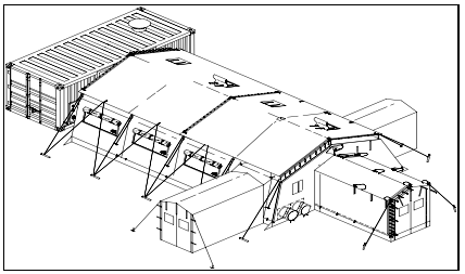
Figure 3·2. Containerized Batch Laundry Subsystem
CONTAINERIZED LATRINE
3-12. The containerized latrine is housed in a 20-foot modified general cargo container that includes all the equipment necessary to operate it. A double sink, three-person urinal, six toilets, a water heater, utility connectors (potable water, black water, and electrical), and a circuit breaker panel are permanently installed within the container. The exhaust fan is mounted on top of the container and must be removed prior to movement and storage. The containerized latrine uses utility/service panels for easy connection and control of potable water, black water, and electrical power. Black water is contained in the main waste tank below the toilets and collected with the waste water evacuation tank/trailer (WWET/T) through the service panel. One containerized latrine is designed to support 150 personnel on a continuous basis. A supervisor and two Soldiers are required to set up the latrine. Two additional Soldiers are temporarily required to assist in the initial installation of the ECU. See Figure 3-3 for the containerized latrine subsystem. Available publications on this subsystem are listed in the reference section located near the rear of this field manual.
3-13. Containerized latrine components include: modified general cargo container; ECU, PDISE and cables; potable and black water systems; and for optional use - a 3K gallon collapsible fabric storage tank and pump.
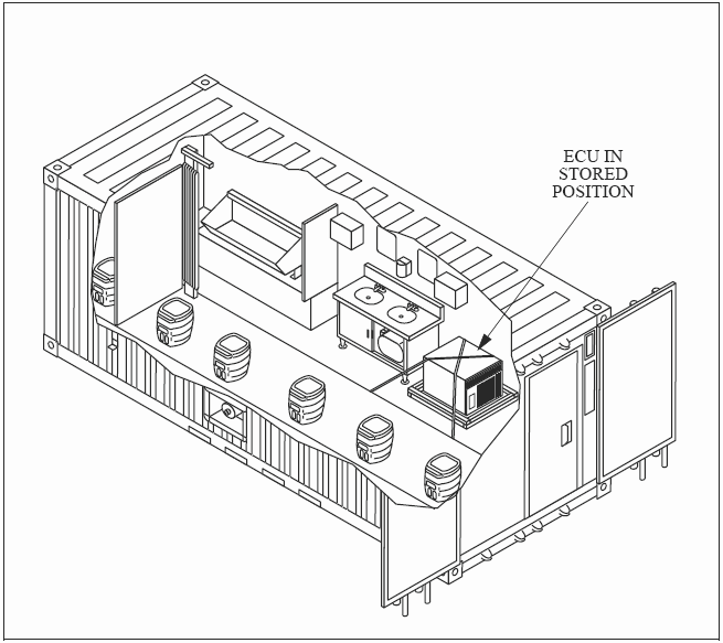
Figure 3·3. Containerized Latrine Subsystem
FOOD SERVICE SUBSYSTEM (ALL ELECTRIC)
3-14. The Force Provider food service subsystem consists of climate-controlled TEMPER facilities for dining, food preparation, kitchen and sanitation areas and the necessary equipment to provide three hot meals daily when local, existing support is not readily available. Future plans call for the use of containerized, all electric kitchens. The TEMPERs are joined together with vestibules and bump-through doors. A supervisor and 26 Soldiers are required to set up the 96-foot dining TEMPER. The remaining TEMPERs require two Soldiers per arch for erection. A utilities equipment repairer is required to supervise and assist in erecting the 600 cubic-foot walk-in refrigerators positioned outside the food preparation area. Hand washing facilities must be available near the entrance of the dining facility. See Figure 3-4 for a sample layout of the food service subsystem.
3-15. A typical Force Provider module contains one all-electric food service subsystem. Key components include: TEMPERS for dining, kitchen, food preparation and sanitation operations; large walk-in refrigerators; potable and gray water equipment and hoses; PDISE, ECU and M-80 water heater; and grease trap. Food preparation equipment includes force convection double ovens, griddles, floor-mounted braising pans, steam kettles, steam tables and assorted preparation, sanitation and serving equipment and accessories. Available publications for the food service subsystem are listed in the reference section located near the rear of this field manual.
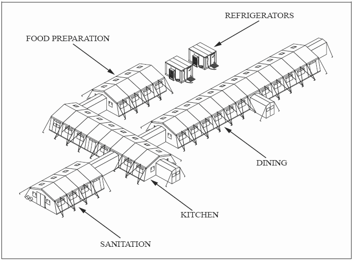
Figure 3·4. Force Provider Food Service Subsystem (all electric)
BULK FUEL STORAGE AND DISTRIBUTION SUBSYSTEM
3-16. The petroleum storage and distribution subsystem provides JP-8/diesel fuel and MOGAS for Force Provider operations. It consists of three separate functional areas/capabilities: bulk JP-8/Diesel fuel storage and distribution; bulk gasoline storage and distribution; optional JP-8/Diesel fuel storage and distribution to support Army Prime Power operations; and required firefighting and grounding equipment. Organic equipment authorized to the Force Provider Company includes a 5,000-gallon tanker and two 1,200 gallon- tank and pump units for refueling 500 gallon drums at each of the nine power generation clusters within the area of operations. The petroleum storage and distribution subsystem does not require electrical power generation for its operations. A supervisor and four Soldiers are required for setup of the current system. Future plans call for a fuel rack system referred to as the Force Provider fuel system, which incorporates a m50 gallon per minute electric pump and separator. See Figure 3-5 for equipment within the subsystem. Available publications for the fuel systems are listed in the reference section located at the rear of this field manual. Major components of the subsystem are listed below.
3-17. The bulk JP-8/diesel fuel storage and distribution equipment consists of:
• Forward area refueling equipment (FARE) with 100-GPM pumping assembly and 100-GPM filter/separator and required hoses
• 10,000-gallon collapsible fabric tanks
• Berm liner assemblies
• Various hoses and adapters
• Fuel spillage control equipment
• 500-gallon drums for each power generation cluster
3-l8. The bulk gasoline storage and distribution equipment consists of:
• 500-gallon collapsible fabric drums
• FARE with l00-GPM pump and l00-GPM filter/separator and required hoses
• Various hoses and adapters
• Nozzle assemblies
• Fuel spillage control equipment
• Five-gallon fuel cans for transporting fuel to water chillers
3-l9. The optional Bulk JP-8/Diesel Storage and Distribution equipment for Army Prime Power consists of:
• l0,000-gallon collapsible fabric tanks with berm liner assemblies
• Hoses and adapters for connection to Prime Power generation sets
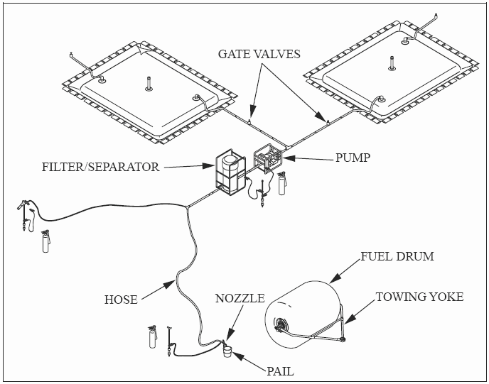
Figure 3·5. Fuel Storage and Distribution Equipment
POTABLE WATER DISTRIBUTION AND STORAGE SUBSYSTEM
3-20. The potable water distribution and storage subsystem consists of four 20,000-gallon storage and distribution sites which provide potable water to the laundry, shower, food service, and latrine subsystems, and on occasion the medical treatment facility (MTF). Also provided are four 400-gallon water tank trailers to distribute water to other locations within the area of operations. A supervisor and four Soldiers are required for the setup of a water distribution site. See Figure 3-6 for sample layout of the water distribution system. Available publications for the water distribution system are listed in the reference section located near the rear of this field manual.
3-21. A Force Provider module contains one potable water distribution and storage subsystem. Major components of the subsystem are listed below:
• 20,000-gallon collapsible fabric water tanks and liner
• Discharge hoses
• Electric water pump
• Pressure tank/switch assembly
• Valves, fittings, nozzle kits, and accessories
• 400-gallon water tank trailers
• Expansion tank assemblies
• Hypo-chlorination units
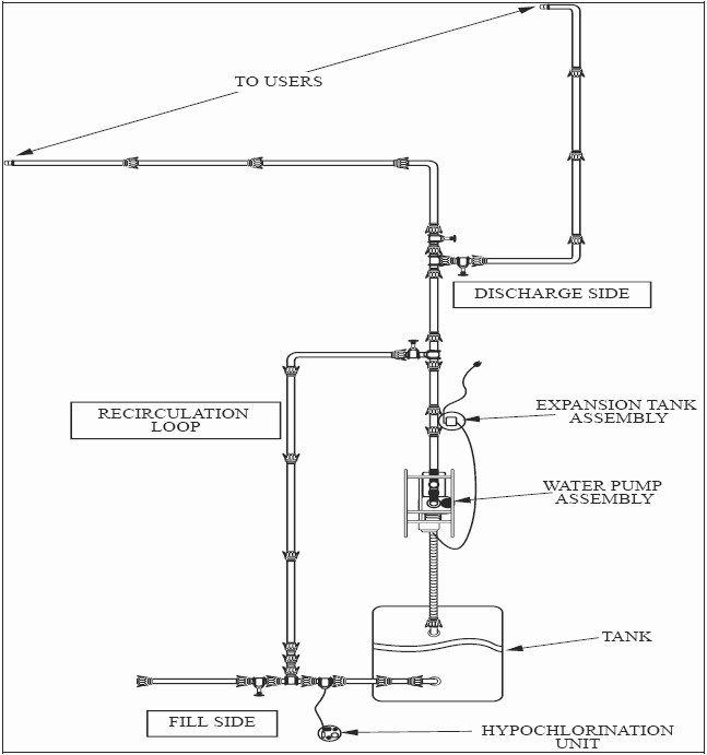
Figure 3·6. Potable Water Distribution and Storage Subsystem
GRAYWATER COLLECTION SUBSYSTEM
3-22. The Gray water Collection Subsystem collects, stores, and disperses gray water from the food service subsystem, containerized batch laundries and portable field shower assemblies. It consists of two 20,000- gallon collapsible fabric tanks for collection, polyvinyl chloride (PVC) pipe, suction/discharge hoses, assorted fittings, and valves and connector kits to interface to the subsystem's sewage ejection pumps. To move gray water off-site, a mobile tank and pump truck or two 125-gallons per minute (GPM) pumps can be used. An optional tank draining kit (with a 125-GPM pump) is available when gray water is pumped into a municipal sewer system or field-expedient disposal site. Four Soldiers are required to set up the 20,000-gallon tanks. The containerized batch laundry washers employ a water reuse system, where water from a previous wash cycle can be collected and saved in tanks for use in subsequent cycles. Future plans call for incorporation of a shower water re-use system which promises to further reduce Force Provider water requirements. The QM Force Provider Company is not authorized the appropriate personnel to setup, operate, and maintain the gray water subsystem. This is a responsibility of the engineer unit assets within the area of operations.
POWER GENERATION SUBSYSTEM
3-23. The power generation subsystem provides the electrical power required to operate a Force Provider module. The system is divided into nine power generation clusters, strategically placed in support of one or more of the module subsystems. See Figure 3-8 for sample layout of a power generation cluster. Available publications for the power system are listed in the reference section located near the rear of this field manual. Each power generation cluster contains:
• Tactical quiet generators (TQGs)
• 500-gallon collapsible fuel tank and liner
• Fire extinguisher
• Grounding equipment for fuel tank
• Junction boxes
• PDISE systems with cables
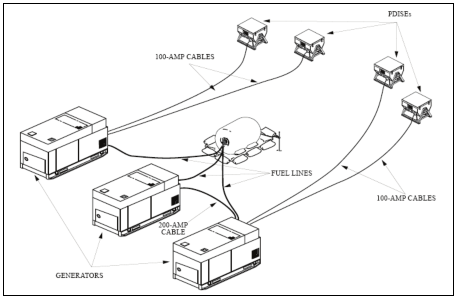
Figure 3·7. Layout of a Power Generation Cluster
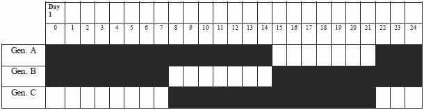
3-24. The generators are operated on a two-on/one-off rotating duty cycle. See Table 3-2 for a sample power generator schedule. At no time should all three generators be operating simultaneously. When commercial power or Army Prime Power is available, a power distribution loop and step-down transformers are required and will be provided and maintained by the Prime Power Team. Two Soldiers are required to install the PDISE units, junction boxes and cables. A forklift is required for positioning the TQGs. The 500-gallon drum with liner will be installed and operated by the petroleum and distribution section personnel.
Table 3·2. Sample Power Generator Schedule
OPTIONAL COLD WEATHER KIT
3-25. The cold weather kit is not standard equipment for the Force Provider module. If operations are anticipated in temperatures below 32°F, then a cold weather kit must be requisitioned along with the module. Specific heaters and TEMPER components must be installed during setup. See Appendix C for a list of items contained in the cold weather kit. Major components of the kit include:
• Army space heaters (ASH)
• 64-foot TEMPERs for the water storage tanks
• Heat-traced hoses for the water distribution subsystem
• Insulated flooring for specific TEMPERs
• Additional TEMPER for waste water evacuation tank and trailer (WWET/T)
• Tools
OPTIONAL PRIME POWER KIT
3-26. The Force Provider optional Prime Power kit is compatible with all U.S. military Prime Power generators (750 KW) or commercial generators. All connections to the transformers must be accomplished by the U.S. Army Prime Power Company or personnel with equivalent certification. The kit consists of 12 transformers that are rated for 150 KVA, 4160V DELTA, 208/120V WYE cable, conductor, 2/0, shielded 5 KV, 133%, direct burial up to 1800 feet.