M966-MOUNTED TOW/TOW 2
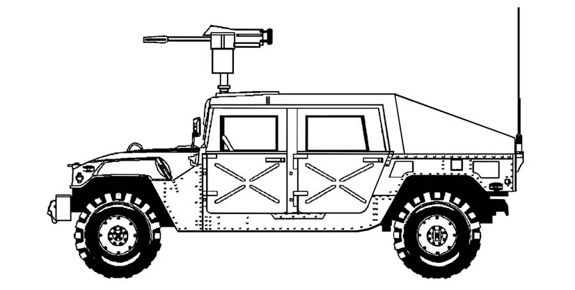
The M966-mounted TOW is a one-vehicle (1 1/4-ton truck) combat system that is air-transportable, versatile, maintainable, and survivable (Figure 3-1). Its 16-inch ground clearance, four-wheel independent suspension, steep approach and departure angles of 60-percent gradation, side slope of 40 percent, and 30-inch (without kit, 60-inch with kit) water-fording capability provides the off-road mobility and speed needed in combat. The vehicle carries one complete launcher system, six encased missiles, and a three-man crew. This chapter discusses the duties of the crew and the detailed operations of the weapon system.
Figure 3-1. M966-mounted TOW.
Section I. INDIVIDUAL DUTIES AND RESPONSIBILITIES
The three-man crew consists of the squad leader, the gunner, and the driver-loader. The duties and responsibilities of each crew member are discussed in the following paragraphs.
3-1. SQUAD
LEADER
The squad leader is responsible for the combat readiness and tactical employment of his squad. This includes discipline, health and welfare, training, and maintenance of equipment and weapons. Other specific duties include the following:
• Directing the driver over the exact route.
• Detecting and identifying targets.
• Issuing fire commands.
3-1
FM 3-22.34
• Controlling fire and movement.
• Supervising and assisting in dismounting and assembly of the M220-series TOW launcher.
• Employing the squad according to the orders of the section leader.
• Selecting primary, alternate, and supplementary firing positions.
• Requesting squad resupply.
• Informing the section leader of events that affect the tactical situation and of the status of his crew.
• Carrying the tripod, launch tube, coolant cartridges, battery case or BPCs, and binoculars when the TOW is used in the ground mode.
• Acting as the gunner when needed.
• Assisting the gunner in system check-out procedures.
• Supervising construction of the TOW firing position.
• Determining the direction of fire.
3-2. GUNNER
Specific duties of the gunner include the following:
• Conducting system check-out procedures.
• Acquiring, recognizing, and identifying armored vehicles.
• Determining if a target can be engaged.
• Engaging targets.
• Recognizing and eliminating firing-angle limitations.
• Adjusting the gunner’s platform before stowing the MGS.
• Stowing the TVPC in the MGS and stowing the MGS, nightsight, and traversing unit.
• Preparing range cards for the TOW.
• Removing the nightsight, daysight tracker, launch tube, traversing unit, and MGS when the TOW is used in the ground mode.
• Carrying the MGS and daysight tracker to the firing position when the TOW
is used in the ground mode.
3-3. DRIVER-LOADER
The driver-loader is a dual-purpose position in the M966 TOW squad. Specific duties of the driver-loader include the following:
• Driving the M966.
• Maintaining the vehicle.
• Camouflaging the vehicle.
• Carrying the traversing unit, encased missile, nightsight, and collimator to the firing position when the TOW is used in the ground mode.
• Securing the area.
• Stowing battery assembly, collimator, encased missiles, daysight tracker, spare battery case, coolant cartridges and batteries (or BPCs), and tripod on the M966 with the assistance of the squad leader.
• Maintaining radio equipment.
• Removing misfired missiles.
3-2
FM 3-22.34
Section II. OPERATION PROCEDURES
Before using the M966-mounted TOW/TOW 2, the squad must install the M220-series TOW launcher and encased missiles and must prepare the M966 for TOW firing. (To install an M220A1 TOW launcher and encased missiles on an M966, see TM 9-1425-472-12. To install an M220A2 TOW launcher and encased missiles on an M966, see TM
9-1425-450-12.)
3-4. EQUIPMENT
STORAGE
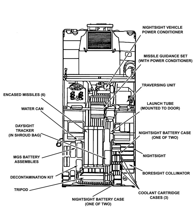
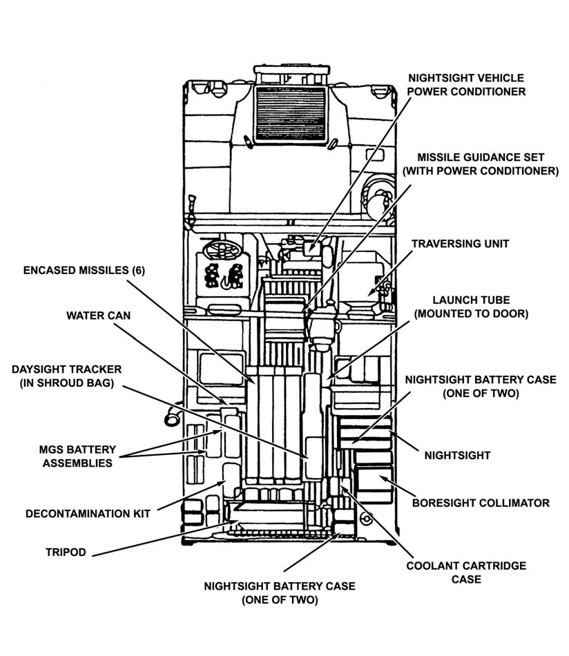
The TOW system components are stored in the interior of the vehicle (Figure 3-2
[M220A1], page 3-4 and Figure 3-3 [M220A2], page 3-5).
a. Six encased missiles are stowed in the missile racks on the left rear of the cargo area.
b. The traversing unit is stowed on the traversing unit adapter behind the right front passenger seat.
c. The MGS is stowed on the gunner’s platform between the left and right rear passenger seat.
d. The nightsight and collimator are stowed on the right cargo shelf.
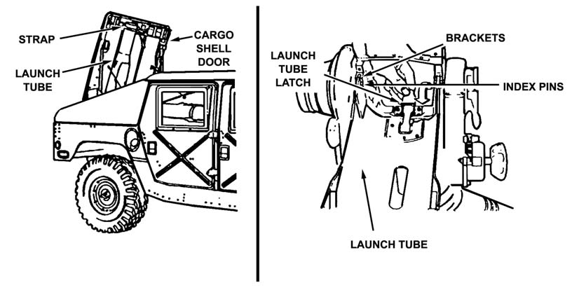
e. The launch tube is stowed on the right side of the cargo shell door.
f. The BPC and spare battery pack, or the nightsight coolant cartridges and the 4.8-volt nickel cadmium battery, are stowed in the floor bracket next to the right wall of the cargo shelf.
g. The daysight tracker is stowed in the floor bracket next to the missile rack.
h. The battery assemblies are stowed in the battery rack above the missile rack.
i. The tripod is stowed retracted, lying across the rear of the cargo area.
j. The TVPC is stowed in the MGS.
3-3
FM 3-22.34
Figure 3-2. Stowing M220A1 on M966.
3-4
FM 3-22.34
Figure 3-3. Stowing M220A2 on M966.
3-5.
HMMWV INTERCHANGEABLE MOUNT SYSTEM
The HMMWV Interchangeable Mount System (HIMS) is used to convert an M966 TOW
HMMWV carrier into an automatic weapons platform (Figure 3-4, page 3-6). The HIMS
provides units equipped with M966 TOW HMMWV carriers with low cost, quick, and effective options for tailoring forces for contingency missions. The HIMS contains two parts. (The HIMS technical data package contains the information needed to operate the HIMS and where to find the materials needed. TM 9-2320-280-10 contains the combat loading plans for the vehicle.)
a. Part one is an armament mount panel assembly with pintle that mounts on the M1025 armament HMMWV carrier. This part is interchangeable with the missile 3-5
FM 3-22.34
guidance tray on the M966 TOW HMMWV carrier. The common turret ring of the two vehicles will accommodate the armament mount panel assembly using existing holes. No modifications are required.
b. Part two consists of a locally fabricated internal floor stowage plate that has automatic weapons stowage brackets, ammunition stowage trays, and footman tie-down straps already mounted for quicker emplacement. This plate is made of sheet aluminum and is mounted in the floor of the M966 TOW HMMWV carrier after removal of selected items of the TOW bracketry.
Figure 3-4. M966 with HIMS.
3-6.
PREPARATION OF AN M966 FOR TOW FIRING
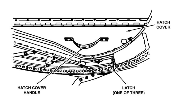
The three-man crew prepares the M966 for TOW firing by performing the following: a. The gunner, driver-loader, and squad leader release the latches securing the hatch cover (Figure 3-5). The driver-loader enters the right rear passenger door.
b. The gunner removes the MGS from its stowed position.
(1) The gunner unlatches the retaining strap securing the MGS.
(2) The gunner releases the latches to remove the MGS cover and hands the cover to the squad leader.
(3) The squad leader stows the MGS cover in the front passenger’s footwell of the vehicle.
(4) The gunner tilts the MGS to the vertical position on the gunner’s platform and releases the lower coupling clamp on the traversing unit adapter.
c. The gunner positions the weapon station. The gunner opens the hatch and enters the weapon station, secures the hatch with the retaining latch, and rotates the weapon station by pulling up on the brake handle so that the backrest is toward the rear of the vehicle. To lock the weapon station, the gunner pushes down on the brake handle.
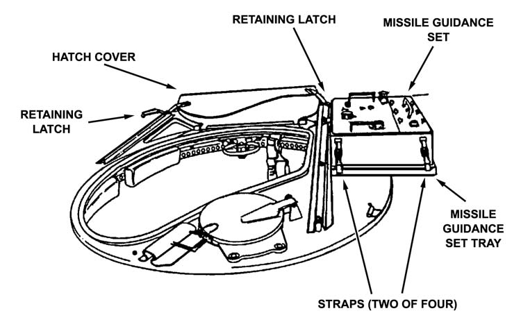
d. The gunner lifts the MGS through the weapon station, places it on the MGS tray, and secures it with the straps (Figure 3-6, page 3-8).
e. The gunner installs the traversing unit.
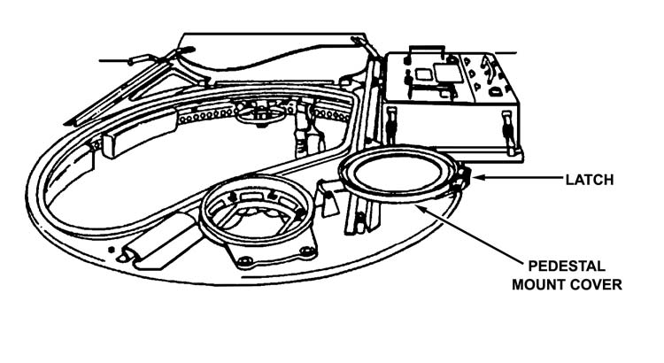
(1) The gunner opens the pedestal mount cover and secures it (Figure 3-7, page 3-8).
3-6
FM 3-22.34
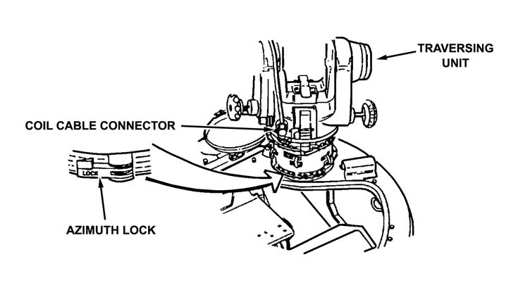
(2) The gunner lifts the traversing unit with adapter attached from the stowage base and secures the traversing unit to the pedestal mount with the coupling clamp ensuring that the traversing unit azimuth lock is toward the rear of the vehicle.
(3) The squad leader pulls the coil cable out of its retaining cup and hands it to the gunner (Figure 3-8, page 3-9).
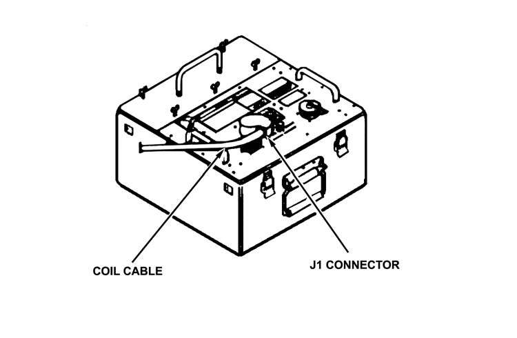
f. The gunner connects the coil cable connector by aligning the yellow indexing line on the coil cable connector with the yellow indexing line on the J1 connector on the MGS
(Figure 3-9, page 3-9). He turns the nut on the coil cable connector in the direction of the arrow until the red mark (band) on the M1 connector on the MGS cannot be seen. (Do not apply downward pressure on the coil cable connector. This can cause misalignment and bent pins.)
CAUTION
Ensure that no dirt is in the end of the coil cable
connector. Dirt can cause a bad connection with
the MGS, resulting in poor system operations.
NOTE:
On the MGS for the basic TOW, push down to seat the coil cable connector on the M1 connector and tighten the locking nut.
Figure 3-5. Hatch cover and latch.
3-7
FM 3-22.34
Figure 3-6. Hatch cover retaining latches and MIGS tray.
Figure 3-7. Pedestal mount cover and latch.
3-8
FM 3-22.34
Figure 3-8. Coil cable connector.
Figure 3-9. Coil cable connector and J1 connector.
g. The gunner installs the launch tube.
(1) The driver-loader uses the forward latch to open the cargo shell door and hands the launch tube to the gunner.
(2) The gunner installs the launch tube on the traversing unit and secures it with the launch tube latch (Figure 3-10, page 3-10).
3-9
FM 3-22.34
Figure 3-10. Launch tube latch.
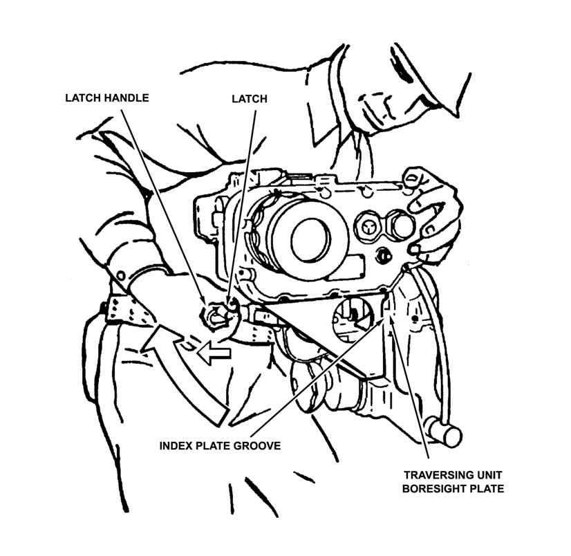
h. The gunner installs the daysight tracker.
(1) The driver-loader hands the daysight tracker to the gunner.
(2) The gunner mounts the daysight tracker on the traversing unit boresight plate. He secures the daysight tracker by locking the latch handle (Figure 3-11).
(3) The driver-loader stows the nightsight case in its bracket.
(4) The squad leader connects connector P2 of the TVPC power cable to the power conditioner cable.
(5) The squad leader unwinds the nightsight power conditioner cable and TVPC cable and hands both to the gunner.
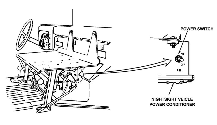
(6) The gunner connects the nightsight power cable 2W2 to the nightsight input power conditioner J1 (Figure 3-12, page 3-12), then connects the TVPC power cable P1
to connector J1.
(7) The squad leader turns on the TVPC.
(8) The gunner turns on the power conditioner.
(9) The gunner checks steps 10 through 15 of system self-test on TOW 2 (positions 1
and 7 on basic TOW), then collimates the nightsight.
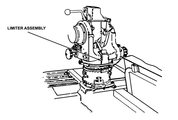
NOTE: The limiter assembly limits elevation to 20 degrees and depression to 10
degrees. If the limiter is used, the gunner makes sure both elevation and depression limiters are in the up position and pinned (Figure 3-13, page 3-12).
3-10
FM 3-22.34
Figure 3-11. Daysight tracker on traversing unit boresight plate.
WARNING
Injury to the gunner and damage to the equipment
can occur if the TOW system is fired at angles
greater than 20 degrees or less than -20 degrees
for all firing positions except over the cargo shell
door. If firing over the cargo shell door, firing
angles should not be greater than 20 degrees or
less than -13 degrees. Pressure waves and flying
debris can cause injury to personnel and damage
to equipment.
3-11
FM 3-22.34
Figure 3-12. Nightsight power cable 2W2, J1 connector,
and vehicle power conditioner.
Figure 3-13. Limiter assembly location.
3-7. LOADING,
ARMING, AND UNLOADING
The procedures for loading, arming, and unloading the M966-mounted TOW/TOW 2 are as follows:
a.
Load. Missiles must be unloaded from the missile racks in numerical order. The forward handling ring, preformed packing, and quick-release clamp are saved in case the 3-12
FM 3-22.34
missile is not fired. If missile diaphragms get damaged while loading, the missile can still be fired. The following procedures are performed to load the M966-mounted TOW/TOW 2.
WARNING
Never open one end of the cargo shell door until
the opposite end is securely closed. Personnel
injury, equipment damage, or mission abort will
occur if both ends open at the same time.
(1) On the traversing unit, the gunner ensures that the launch tube is locked in the 8-degree down position. He pushes the locking handle forward, then up, and opens the bridge clamp.
CAUTIONS
1. Do not drop an encased missile. Handling rings or
launch container may be bent or damaged.
2. Do not break the diaphragm on the end of an
encased missile. If water gets into the launcher
container, the missile can be damaged.
3. Do not dispose of bad missiles. If an encased
missile is damaged or handling rings are badly
bent, return the encased missile to the ammunition
unit for inspection.
4. Be careful not to punch a hole in an encased
missile diaphragm when the forward handling ring
is removed.
(2) The driver-loader unlatches and raises the cargo shell door using the forward latch. He removes the quick-release clamp and forward handling ring from the encased missile.
WARNING
Clear all personnel from the firing danger zone
before proceeding with missile loading procedure.
(a) The driver-loader turns the inside portion of the protective cover two complete turns counterclockwise, and he removes it from the electrical connector. (The protective cover is kept for future use.)
3-13
FM 3-22.34
(b) He turns the encased missile so that the electrical connector is facing up and hands it to the gunner.
(3) The gunner takes the encased missile from the driver-loader. He raises the back end of the missile and slides it forward and down into the launch tube until the missile indexing lugs are firmly in place. The gunner lowers the back end of the encased missile ensuring that the electrical connector joins with the bridge clamp. He lowers the bridge clamp and pushes down on the top of it. He pulls the bridge clamp locking handle downward and backward to lock the encased missile in the launch tube.
DANGER
CARGO SHELL DOOR MUST BE CLOSED AND
SECURELY LATCHED AT BOTH ENDS BEFORE
FIRING A MISSILE. FIRING A MISSILE WITH THE
DOOR NOT SECURE WILL CAUSE INJURY TO
PERSONNEL, DAMAGE TO EQUIPMENT, OR
MISSION ABORT.
b.
Arm. The following procedures are performed to arm the M966-mounted TOW/TOW 2.
(1) The driver-loader closes the cargo shell door.
(2) The gunner makes sure the cargo shell door is securely latched at the forward end.
WARNING
Do not raise arming lever until ready