5-3. Ground-to-Air Panel System
a. The panel system is a method ground troops use to communicate, to a limited degree, with aircraft by displaying panels on the ground. There are two types of panels: marking and identifying colored panels, and black and white panels for transmitting messages.
(1) The marking and identifying panels are made in fluorescent colors. The panels are used to mark positions and identify friendly units. These panels can be ordered through the supply system using the nomenclature Panel Marker, Aerial, Liaison (Figure 5-23).
(2) Black and white panel sets are arranged on light or dark terrain backgrounds. They are used to transmit brief messages or to identify a unit. This is done by using the combined panel system and the panel recognition code in the unit's communications-electronics operating instructions.
b. Panels (if constructed locally) should be large enough to permit easy reading from the air. There should be as much color contrast as possible between the symbols and the background. Panels should beat least six feet long and two feet wide.
c. Select a relatively flat, clear area of ground about 40 by 130 feet. This area is large enough to display messages and special signs. For message drop and pickup, the area should be clear of obstacles which could prevent aircraft from flying into the wind at reduced airspeed and low altitude.
d. When using the panel system, one of the panels is used as a base panel. Place the base panels first and keep them in place as long as panel signaling is in progress. The distance between panels is one panel length throughout, when space is available. Change from one panel figure to another as soon as possible by shifting, adding, or removing panels (other than the base panels). The index panel is the first removed and the last laid out when the display is changed. Remove all panels from view that are not used for a particular display.
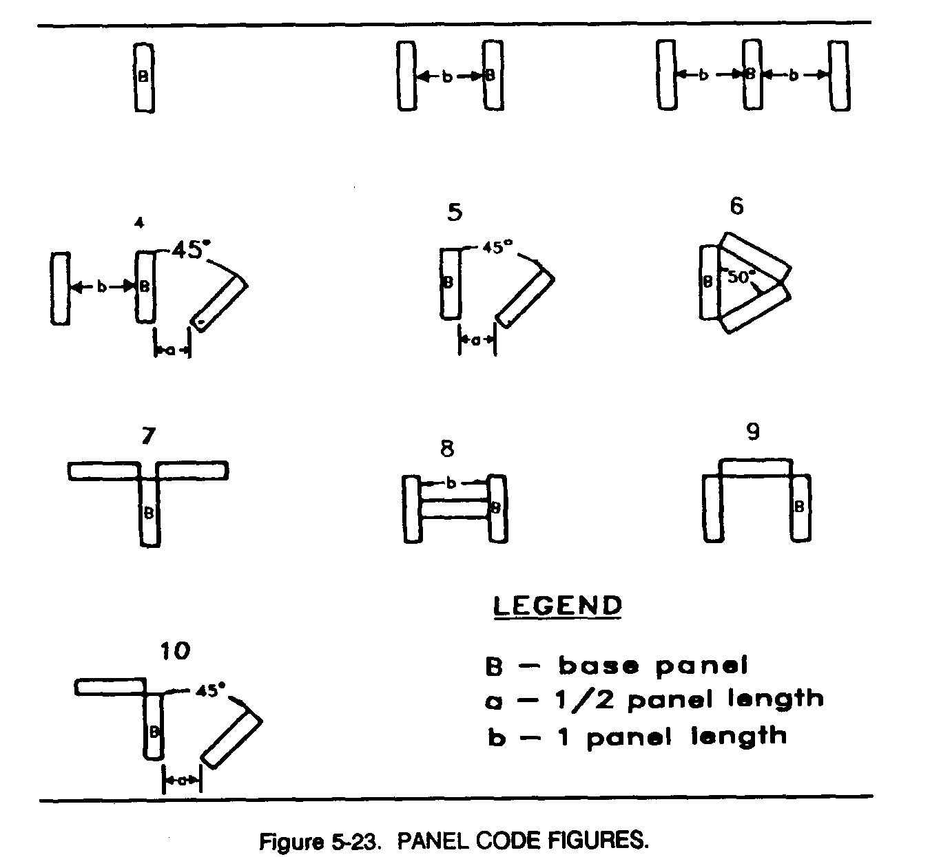
e. The unit's communications-electronics operating instructions assign specific vocabulary, receipting, acknowledging, and identification procedures. Code meanings are normally based on this manual, with local amplification, while the numbers associated with the meanings are determined by the unit's communications-electronics operating instructions. They are changed periodically to prevent compromise.
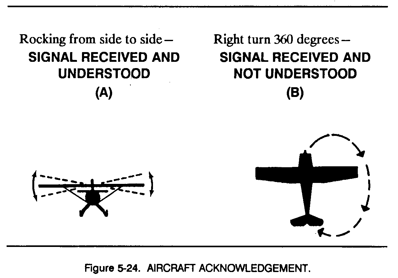
f. An aircraft pilot indicates that ground signals have been understood by rocking the wings laterally, by flashing a green signal lamp, or by any prearranged signal CA, Figure 5-24). The pilot indicates that ground signals are not understood by making a 360degree turn to the right, by flashing a red signal lamp, or by any prearranged signal CB, Figure 5-24). Each panel display is acknowledged. A pilot requests a unit to display an identification code by a prearranged signal. In no case does a unit display an identification code until the aircraft has been identified as friendly.
g. Ground units can identify themselves as friendly elements to a pilot by using a panel marker or its equivalent. This panel marker is displayed on combat vehicles to identify the vehicle as friendly to the pilot. It is also displayed on the ground for other purposes; for example, to identify friendly front lines and dismounted troops. The color and pattern of the display are prescribed in unit standing operating procedures.
5-4. Special Panel Signals
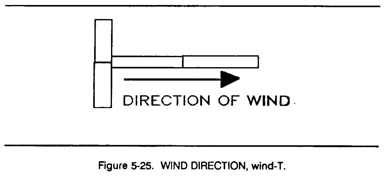
a. Wind-T. The T is used to indicate wind direction. It represents an aircraft flying into the wind. The wind-T is two panels wide and two panels long (Figure 5-25).
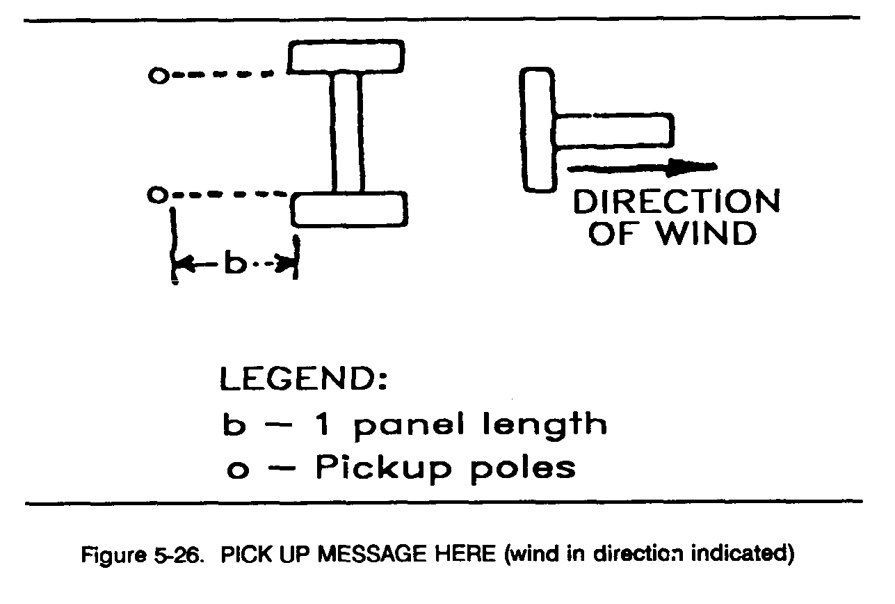
b. Message Pickup. This message is displayed by the figure 8 (H) with the wind-T centered below it. The crossbar of the H (8) is not placed in position until the message is ready to be picked up. The pickup poles are placed so that each pole is one panel-length away from the comer of the nearest panel (Figure 5-26).
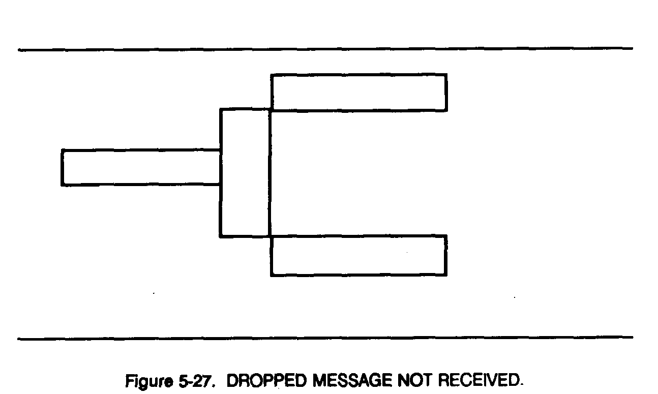
c. Message Drop. When a dropped message is not found, this symbol is displayed in the drop area (Figure 5-27).
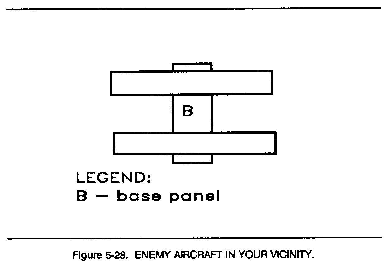
d. Enemy Aircraft. Two panels, placed at right angles to a third and on the axis of any base panel, always means enemy aircraft near even though other parts of the panel display remain in place (Figure 5-28).
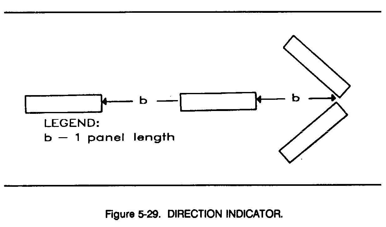
e. Direction Indicator. An arrow made with not less than four panels means "in this direction." This sign is used alone or with the pattern preceding it to complete its meaning (Figure 5-29).