How can we guarantee that a body is in equilibrium and what can we learn from systems that are in equilibrium? There are actually two conditions
that must be satisfied to achieve equilibrium. These conditions are the topics of the first two sections of this chapter.
9.1 The First Condition for Equilibrium
The first condition necessary to achieve equilibrium is the one already mentioned: the net external force on the system must be zero. Expressed as
an equation, this is simply
(9.1)
net F = 0
Note that if net F is zero, then the net external force in any direction is zero. For example, the net external forces along the typical x- and y-axes are zero. This is written as
(9.2)
net Fx = 0 and Fy = 0
Figure 9.2 and Figure 9.3 illustrate situations where net F = 0 for both static equilibrium (motionless), and dynamic equilibrium (constant velocity).
Figure 9.2 This motionless person is in static equilibrium. The forces acting on him add up to zero. Both forces are vertical in this case.
Figure 9.3 This car is in dynamic equilibrium because it is moving at constant velocity. There are horizontal and vertical forces, but the net external force in any direction is zero. The applied force F app between the tires and the road is balanced by air friction, and the weight of the car is supported by the normal forces, here shown to be equal
for all four tires.
However, it is not sufficient for the net external force of a system to be zero for a system to be in equilibrium. Consider the two situations illustrated in
Figure 9.4 and Figure 9.5 where forces are applied to an ice hockey stick lying flat on ice. The net external force is zero in both situations shown in the figure; but in one case, equilibrium is achieved, whereas in the other, it is not. In Figure 9.4, the ice hockey stick remains motionless. But in
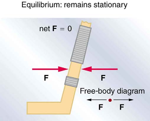

CHAPTER 9 | STATICS AND TORQUE 291
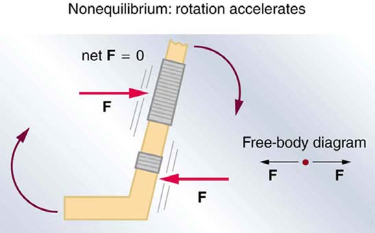
Figure 9.5, with the same forces applied in different places, the stick experiences accelerated rotation. Therefore, we know that the point at which a force is applied is another factor in determining whether or not equilibrium is achieved. This will be explored further in the next section.
Figure 9.4 An ice hockey stick lying flat on ice with two equal and opposite horizontal forces applied to it. Friction is negligible, and the gravitational force is balanced by the support of the ice (a normal force). Thus, net F = 0 . Equilibrium is achieved, which is static equilibrium in this case.
Figure 9.5 The same forces are applied at other points and the stick rotates—in fact, it experiences an accelerated rotation. Here net F = 0 but the system is not at equilibrium. Hence, the net F = 0 is a necessary—but not sufficient—condition for achieving equilibrium.
PhET Explorations: Torque
Investigate how torque causes an object to rotate. Discover the relationships between angular acceleration, moment of inertia, angular
momentum and torque.
Figure 9.6 Torque (http://cnx.org/content/m42170/1.4/torque_en.jar)
9.2 The Second Condition for Equilibrium
Torque
The second condition necessary to achieve equilibrium involves avoiding accelerated rotation (maintaining a constant angular velocity. A rotating
body or system can be in equilibrium if its rate of rotation is constant and remains unchanged by the forces acting on it. To understand what
factors affect rotation, let us think about what happens when you open an ordinary door by rotating it on its hinges.
Several familiar factors determine how effective you are in opening the door. See Figure 9.7. First of all, the larger the force, the more effective it is in opening the door—obviously, the harder you push, the more rapidly the door opens. Also, the point at which you push is crucial. If you apply your
force too close to the hinges, the door will open slowly, if at all. Most people have been embarrassed by making this mistake and bumping up against
292 CHAPTER 9 | STATICS AND TORQUE
a door when it did not open as quickly as expected. Finally, the direction in which you push is also important. The most effective direction is
perpendicular to the door—we push in this direction almost instinctively.
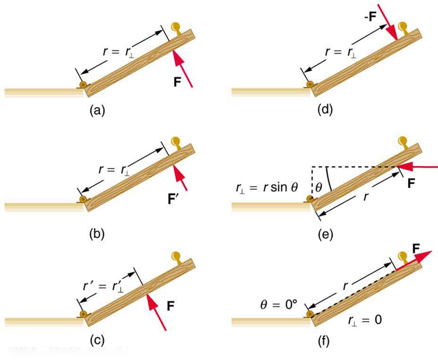
Figure 9.7 Torque is the turning or twisting effectiveness of a force, illustrated here for door rotation on its hinges (as viewed from overhead). Torque has both magnitude and direction. (a) Counterclockwise torque is produced by this force, which means that the door will rotate in a counterclockwise due to F . Note that r⊥ is the perpendicular distance of the pivot from the line of action of the force. (b) A smaller counterclockwise torque is produced by a smaller force F′ acting at the same distance from the hinges
(the pivot point). (c) The same force as in (a) produces a smaller counterclockwise torque when applied at a smaller distance from the hinges. (d) The same force as in (a), but
acting in the opposite direction, produces a clockwise torque. (e) A smaller counterclockwise torque is produced by the same magnitude force acting at the same point but in a
different direction. Here, θ is less than 90º . (f) Torque is zero here since the force just pulls on the hinges, producing no rotation. In this case, θ = 0º .
The magnitude, direction, and point of application of the force are incorporated into the definition of the physical quantity called torque. Torque is the
rotational equivalent of a force. It is a measure of the effectiveness of a force in changing or accelerating a rotation (changing the angular velocity
over a period of time). In equation form, the magnitude of torque is defined to be
τ
(9.3)
= rF sin θ
where τ (the Greek letter tau) is the symbol for torque, r is the distance from the pivot point to the point where the force is applied, F is the
magnitude of the force, and θ is the angle between the force and the vector directed from the point of application to the pivot point, as seen in
Figure 9.7 and Figure 9.8. An alternative expression for torque is given in terms of the perpendicular lever arm r ⊥ as shown in Figure 9.7 and
Figure 9.8, which is defined as
r
(9.4)
⊥ = r sin θ
so that
τ
(9.5)
= r⊥ F.
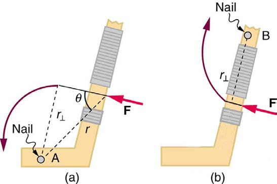
Figure 9.8 A force applied to an object can produce a torque, which depends on the location of the pivot point. (a) The three factors r , F , and θ for pivot point A on a body are shown here— r is the distance from the chosen pivot point to the point where the force F is applied, and θ is the angle between F and the vector directed from the point of application to the pivot point. If the object can rotate around point A, it will rotate counterclockwise. This means that torque is counterclockwise relative to pivot A. (b) In this case, point B is the pivot point. The torque from the applied force will cause a clockwise rotation around point B, and so it is a clockwise torque relative to B.
CHAPTER 9 | STATICS AND TORQUE 293
The perpendicular lever arm r ⊥ is the shortest distance from the pivot point to the line along which F acts; it is shown as a dashed line in Figure
9.7 and Figure 9.8. Note that the line segment that defines the distance r ⊥ is perpendicular to F , as its name implies. It is sometimes easier to find or visualize r ⊥ than to find both r and θ . In such cases, it may be more convenient to use τ = r ⊥ F rather than τ = rF sin θ for torque, but both are equally valid.
The SI unit of torque is newtons times meters, usually written as N · m . For example, if you push perpendicular to the door with a force of 40 N at a
distance of 0.800 m from the hinges, you exert a torque of 32 N·m(0.800 m×40 N×sin 90º) relative to the hinges. If you reduce the force to 20 N,
the torque is reduced to 16 N·m , and so on.
The torque is always calculated with reference to some chosen pivot point. For the same applied force, a different choice for the location of the pivot
will give you a different value for the torque, since both r and θ depend on the location of the pivot. Any point in any object can be chosen to
calculate the torque about that point. The object may not actually pivot about the chosen “pivot point.”
Note that for rotation in a plane, torque has two possible directions. Torque is either clockwise or counterclockwise relative to the chosen pivot point,
as illustrated for points B and A, respectively, in Figure 9.8. If the object can rotate about point A, it will rotate counterclockwise, which means that the
torque for the force is shown as counterclockwise relative to A. But if the object can rotate about point B, it will rotate clockwise, which means the
torque for the force shown is clockwise relative to B. Also, the magnitude of the torque is greater when the lever arm is longer.
Now, the second condition necessary to achieve equilibrium is that the net external torque on a system must be zero. An external torque is one that is
created by an external force. You can choose the point around which the torque is calculated. The point can be the physical pivot point of a system or
any other point in space—but it must be the same point for all torques. If the second condition (net external torque on a system is zero) is satisfied for
one choice of pivot point, it will also hold true for any other choice of pivot point in or out of the system of interest. (This is true only in an inertial frame
of reference.) The second condition necessary to achieve equilibrium is stated in equation form as
(9.6)
net τ = 0
where net means total. Torques, which are in opposite directions are assigned opposite signs. A common convention is to call counterclockwise (ccw)
torques positive and clockwise (cw) torques negative.
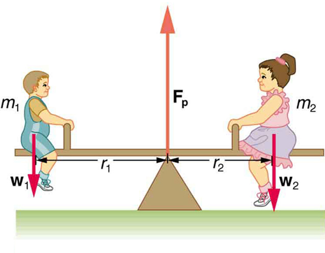
When two children balance a seesaw as shown in Figure 9.9, they satisfy the two conditions for equilibrium. Most people have perfect intuition about seesaws, knowing that the lighter child must sit farther from the pivot and that a heavier child can keep a lighter one off the ground indefinitely.
Figure 9.9 Two children balancing a seesaw satisfy both conditions for equilibrium. The lighter child sits farther from the pivot to create a torque equal in magnitude to that of the heavier child.
Example 9.1 She Saw Torques On A Seesaw
The two children shown in Figure 9.9 are balanced on a seesaw of negligible mass. (This assumption is made to keep the example
simple—more involved examples will follow.) The first child has a mass of 26.0 kg and sits 1.60 m from the pivot.(a) If the second child has a
mass of 32.0 kg, how far is she from the pivot? (b) What is F p , the supporting force exerted by the pivot?
Strategy
Both conditions for equilibrium must be satisfied. In part (a), we are asked for a distance; thus, the second condition (regarding torques) must be
used, since the first (regarding only forces) has no distances in it. To apply the second condition for equilibrium, we first identify the system of
interest to be the seesaw plus the two children. We take the supporting pivot to be the point about which the torques are calculated. We then
identify all external forces acting on the system.
Solution (a)
The three external forces acting on the system are the weights of the two children and the supporting force of the pivot. Let us examine the
torque produced by each. Torque is defined to be
τ
(9.7)
= rF sin θ.
Here θ = 90º , so that sin θ = 1 for all three forces. That means r ⊥ = r for all three. The torques exerted by the three forces are first,
294 CHAPTER 9 | STATICS AND TORQUE
τ
(9.8)
1 = r 1 w 1
second,
τ
(9.9)
2 = – r 2 w 2
and third,
τ
(9.10)
p = r p F p
= 0 ⋅ F p
= 0.
Note that a minus sign has been inserted into the second equation because this torque is clockwise and is therefore negative by convention.
Since F p acts directly on the pivot point, the distance r p is zero. A force acting on the pivot cannot cause a rotation, just as pushing directly on
the hinges of a door will not cause it to rotate. Now, the second condition for equilibrium is that the sum of the torques on both children is zero.
Therefore
τ
(9.11)
2 = – τ 1,
or
r
(9.12)
2 w 2 = r 1 w 1.
Weight is mass times the acceleration due to gravity. Entering mg for w , we get
r
(9.13)
2 m 2 g = r 1 m 1 g.
Solve this for the unknown r 2 :
m
(9.14)
r
1
2 = r 1 m .
2
The quantities on the right side of the equation are known; thus, r 2 is
(9.15)
r 2 = (1.60 m)26.0 kg
32.0 kg = 1.30 m.
As expected, the heavier child must sit closer to the pivot (1.30 m versus 1.60 m) to balance the seesaw.
Solution (b)
This part asks for a force F p . The easiest way to find it is to use the first condition for equilibrium, which is
(9.16)
net F = 0.
The forces are all vertical, so that we are dealing with a one-dimensional problem along the vertical axis; hence, the condition can be written as
(9.17)
net Fy = 0
where we again call the vertical axis the y-axis. Choosing upward to be the positive direction, and using plus and minus signs to indicate the
directions of the forces, we see that
F
(9.18)
p – w 1 – w 2 = 0.
This equation yields what might have been guessed at the beginning:
F
(9.19)
p = w 1 + w 2.
So, the pivot supplies a supporting force equal to the total weight of the system:
F
(9.20)
p = m 1 g + m 2 g.
Entering known values gives
⎛
⎛
(9.21)
F p = ⎛⎝26.0 kg⎞⎠⎝9.80 m/s2⎞⎠ + ⎛⎝32.0 kg⎞⎠⎝9.80 m/s2⎞⎠
= 568 N.
Discussion
The two results make intuitive sense. The heavier child sits closer to the pivot. The pivot supports the weight of the two children. Part (b) can also
be solved using the second condition for equilibrium, since both distances are known, but only if the pivot point is chosen to be somewhere other
than the location of the seesaw’s actual pivot!
Several aspects of the preceding example have broad implications. First, the choice of the pivot as the point around which torques are calculated
simplified the problem. Since F p is exerted on the pivot point, its lever arm is zero. Hence, the torque exerted by the supporting force F p is zero
relative to that pivot point. The second condition for equilibrium holds for any choice of pivot point, and so we choose the pivot point to simplify the
solution of the problem.
CHAPTER 9 | STATICS AND TORQUE 295
Second, the acceleration due to gravity canceled in this problem, and we were left with a ratio of masses. This will not always be the case. Always
enter the correct forces—do not jump ahead to enter some ratio of masses.
Third, the weight of each child is distributed over an area of the seesaw, yet we treated the weights as if each force were exerted at a single point.
This is not an approximation—the distances r 1 and r 2 are the distances to points directly below the center of gravity of each child. As we shall
see in the next section, the mass and weight of a system can act as if they are located at a single point.
Finally, note that the concept of torque has an importance beyond static equilibrium. Torque plays the same role in rotational motion that force plays
in linear motion. We will examine this in the next chapter.
Take-Home Experiment
Take a piece of modeling clay and put it on a table, then mash a cylinder down into it so that a ruler can balance on the round side of the cylinder
while everything remains still. Put a penny 8 cm away from the pivot. Where would you need to put two pennies to balance? Three pennies?
9.3 Stability
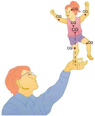
It is one thing to have a system in equilibrium; it is quite another for it to be stable. The toy doll perched on the man’s hand in Figure 9.10, for
example, is not in stable equilibrium. There are three types of equilibrium: stable, unstable, and neutral. Figures throughout this module illustrate
various examples.
Figure 9.10 presents a balanced system, such as the toy doll on the man’s hand, which has its center of gravity (cg) directly over the pivot, so that the torque of the total weight is zero. This is equivalent to having the torques of the individual parts balanced about the pivot point, in this case the
hand. The cgs of the arms, legs, head, and torso are labeled with smaller type.
Figure 9.10 A man balances a toy doll on one hand.
A system is said to be in stable equilibrium if, when displaced from equilibrium, it experiences a net force or torque in a direction opposite to the
direction of the displacement. For example, a marble at the bottom of a bowl will experience a restoring force when displaced from its equilibrium
position. This force moves it back toward the equilibrium position. Most systems are in stable equilibrium, especially for small displacements. For
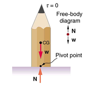
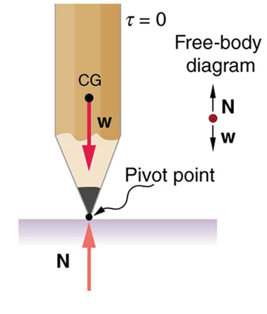
another example of stable equilibrium, see the pencil in Figure 9.11.
Figure 9.11 This pencil is in the condition of equilibrium. The net force on the pencil is zero and the total torque about any pivot is zero.
A system is in unstable equilibrium if, when displaced, it experiences a net force or torque in the same direction as the displacement from
equilibrium. A system in unstable equilibrium accelerates away from its equilibrium position if displaced even slightly. An obvious example is a ball
resting on top of a hill. Once displaced, it accelerates away from the crest. See the next several figures for examples of unstable equilibrium.
296 CHAPTER 9 | STATICS AND TORQUE
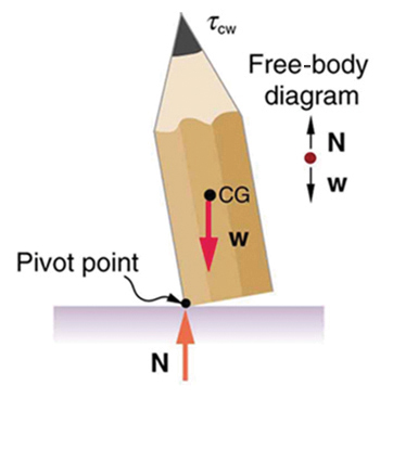
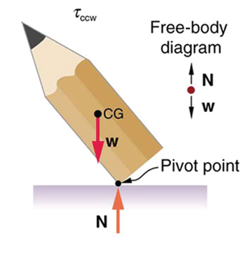
Figure 9.12 If the pencil is displaced slightly to the side (counterclockwise), it is no longer in equilibrium. Its weight produces a clockwise torque that returns the pencil to its equilibrium position.
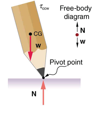
Figure 9.13 If the pencil is displaced too far, the torque caused by its weight changes direction to counterclockwise and causes the displacement to increase.
Figure 9.14 This figure shows unstable equilibrium, although both conditions for equilibrium are satisfied.
CHAPTER 9 | STATICS AND TORQUE 297
Figure 9.15 If the pencil is displaced even slightly, a torque is created by its weight that is in the same direction as the displacement, causing the displacement to increase.
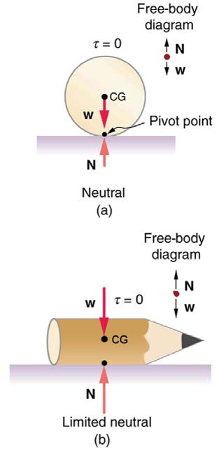
A system is in neutral equilibrium if its equilibrium is independent of displacements from its original position. A marble on a flat horizontal surface is
an example. Combinations of these situations are possible. For example, a marble on a saddle is stable for displacements toward the front or back of
the saddle and unstable for displacements to the side. Figure 9.16 shows another example of neutral equilibrium.
Figure 9.16 (a) Here we see neutral equilibrium. The cg of a sphere on a flat surface lies directly above the point of support, independent of the position on the surface. The
sphere is therefore in equilibrium in any location, and if displaced, it will remain put. (b) Because it has a circular cross section, the pencil is in neutral equilibrium for
displacements perpendicular to its length.
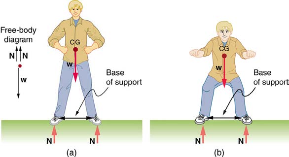
When we consider how far a system in stable equilibrium can be displaced before it becomes unstable, we find that some systems in stable
equilibrium are more stable than others. The pencil in Figure 9.11 and the person in Figure 9.17(a) are in stable equilibrium, but become unstable for
relatively small displacements to the side. The critical point is reached when the cg is no longer above the base of support. Additionally, since the cg
of a person’s body is above the pivots in the hips, displacements must be quickly controlled. This control is a central nervous system function that is
developed when we learn to hold our bodies erect as infants. For increased stability while standing, the feet should be spread apart, giving a larger
base of support. Stability is also increased by lowering one’s center of gravity by bending the knees, as when a football player prepares to receive a
ball or braces themselves for a tackle. A cane, a crutch, or a walker increases the stability of the user, even more as the base of support widens.
Usually, the cg of a female is lower (closer to the ground) than a male. Young children have their center of gravity between their shoulders, which
increases the challenge of learning to walk.
298 CHAPTER 9 | STATICS AND TORQUE
Figure 9.17 (a) The center of gravity of an adult is above