⎞
⎝103 kg
m3⎠⎝9.80 m
s2⎠
= 3.92×10⁵ N
m2 = 392 kPa.
Strategy for (b)
The force exerted on the dam by the water is the average pressure times the area of contact:
(11.20)
F = P¯ A.
Solution for (b)
We have already found the value for P¯ . The area of the dam is A = 80.0 m×500 m = 4.00×10⁴ m2 , so that
(11.21)
F = (3.92×10⁵ N/m2)(4.00×104 m2)
= 1.57×10¹⁰ N.
Discussion
Although this force seems large, it is small compared with the 1.96×10¹³ N weight of the water in the reservoir—in fact, it is only 0.0800% of
the weight. Note that the pressure found in part (a) is completely independent of the width and length of the lake—it depends only on its average
depth at the dam. Thus the force depends only on the water’s average depth and the dimensions of the dam, not on the horizontal extent of the
reservoir. In the diagram, the thickness of the dam increases with depth to balance the increasing force due to the increasing pressure.epth to
balance the increasing force due to the increasing pressure.
Figure 11.11 The dam must withstand the force exerted against it by the water it retains. This force is small compared with the weight of the water behind the dam.
Atmospheric pressure is another example of pressure due to the weight of a fluid, in this case due to the weight of air above a given height. The
atmospheric pressure at the Earth’s surface varies a little due to the large-scale flow of the atmosphere induced by the Earth’s rotation (this creates
weather “highs” and “lows”). However, the average pressure at sea level is given by the standard atmospheric pressure P atm , measured to be
(11.22)
1 atmosphere (atm) = P atm = 1.01×10⁵ N/m2 = 101 kPa.
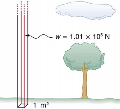
This relationship means that, on average, at sea level, a column of air above 1.00 m2 of the Earth’s surface has a weight of 1.01×10⁵ N ,
equivalent to 1 atm . (See Figure 11.12.)
CHAPTER 11 | FLUID STATICS 365
Figure 11.12 Atmospheric pressure at sea level averages 1.01×10⁵ Pa (equivalent to 1 atm), since the column of air over this 1 m2 , extending to the top of the
atmosphere, weighs 1.01×10⁵ N .
Example 11.4 Calculating Average Density: How Dense Is the Air?
Calculate the average density of the atmosphere, given that it extends to an altitude of 120 km. Compare this density with that of air listed in
Strategy
If we solve P = hρg for density, we see that
(11.23)
ρ¯ = P
hg.
We then take P to be atmospheric pressure, h is given, and g is known, and so we can use this to calculate ρ¯ .
Solution
Entering known values into the expression for ρ¯ yields
(11.24)
ρ¯ =
1.01×10⁵ N/m2
= 8.59×10⁻² kg/m3.
(120×103 m)(9.80 m/s2)
Discussion
This result is the average density of air between the Earth’s surface and the top of the Earth’s atmosphere, which essentially ends at 120 km.
The density of air at sea level is given in Table 11.1 as 1.29 kg/m3 —about 15 times its average value. Because air is so compressible, its
density has its highest value near the Earth’s surface and declines rapidly with altitude.
Example 11.5 Calculating Depth Below the Surface of Water: What Depth of Water Creates the Same Pressure
as the Entire Atmosphere?
Calculate the depth below the surface of water at which the pressure due to the weight of the water equals 1.00 atm.
Strategy
We begin by solving the equation P = hρg for depth h :
(11.25)
h = P
ρg.
Then we take P to be 1.00 atm and ρ to be the density of the water that creates the pressure.
Solution
Entering the known values into the expression for h gives
(11.26)
h =
1.01×10⁵ N/m2
= 10.3 m.
(1.00×10³ kg/m3)(9.80 m/s2)
Discussion
366 CHAPTER 11 | FLUID STATICS
Just 10.3 m of water creates the same pressure as 120 km of air. Since water is nearly incompressible, we can neglect any change in its density
over this depth.
What do you suppose is the total pressure at a depth of 10.3 m in a swimming pool? Does the atmospheric pressure on the water’s surface affect the
pressure below? The answer is yes. This seems only logical, since both the water’s weight and the atmosphere’s weight must be supported. So the
total pressure at a depth of 10.3 m is 2 atm—half from the water above and half from the air above. We shall see in Pascal’s Principle that fluid pressures always add in this way.
11.5 Pascal’s Principle
Pressure is defined as force per unit area. Can pressure be increased in a fluid by pushing directly on the fluid? Yes, but it is much easier if the fluid
is enclosed. The heart, for example, increases blood pressure by pushing directly on the blood in an enclosed system (valves closed in a chamber). If
you try to push on a fluid in an open system, such as a river, the fluid flows away. An enclosed fluid cannot flow away, and so pressure is more easily
increased by an applied force.
What happens to a pressure in an enclosed fluid? Since atoms in a fluid are free to move about, they transmit the pressure to all parts of the fluid and
to the walls of the container. Remarkably, the pressure is transmitted undiminished. This phenomenon is called Pascal’s principle, because it was
first clearly stated by the French philosopher and scientist Blaise Pascal (1623–1662): A change in pressure applied to an enclosed fluid is
transmitted undiminished to all portions of the fluid and to the walls of its container.
Pascal’s Principle
A change in pressure applied to an enclosed fluid is transmitted undiminished to all portions of the fluid and to the walls of its container.
Pascal’s principle, an experimentally verified fact, is what makes pressure so important in fluids. Since a change in pressure is transmitted
undiminished in an enclosed fluid, we often know more about pressure than other physical quantities in fluids. Moreover, Pascal’s principle implies
that the total pressure in a fluid is the sum of the pressures from different sources. We shall find this fact—that pressures add—very useful.
Blaise Pascal had an interesting life in that he was home-schooled by his father who removed all of the mathematics textbooks from his house and
forbade him to study mathematics until the age of 15. This, of course, raised the boy’s curiosity, and by the age of 12, he started to teach himself
geometry. Despite this early deprivation, Pascal went on to make major contributions in the mathematical fields of probability theory, number theory,
and geometry. He is also well known for being the inventor of the first mechanical digital calculator, in addition to his contributions in the field of fluid
statics.
Application of Pascal’s Principle
One of the most important technological applications of Pascal’s principle is found in a hydraulic system, which is an enclosed fluid system used to
exert forces. The most common hydraulic systems are those that operate car brakes. Let us first consider the simple hydraulic system shown in
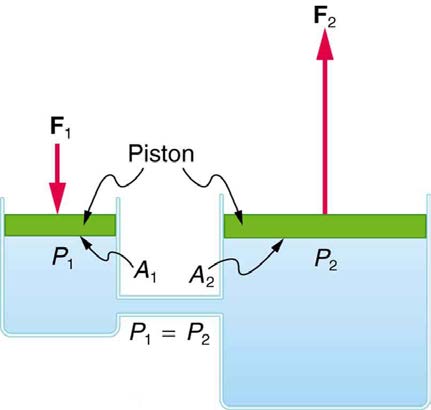
Figure 11.13 A typical hydraulic system with two fluid-filled cylinders, capped with pistons and connected by a tube called a hydraulic line. A downward force F1 on the left piston creates a pressure that is transmitted undiminished to all parts of the enclosed fluid. This results in an upward force F2 on the right piston that is larger than F1
because the right piston has a larger area.
Relationship Between Forces in a Hydraulic System
We can derive a relationship between the forces in the simple hydraulic system shown in Figure 11.13 by applying Pascal’s principle. Note first that the two pistons in the system are at the same height, and so there will be no difference in pressure due to a difference in depth. Now the pressure
due to F 1 acting on area A 1 is simply P 1 = F 1
A , as defined by P = F
1
A . According to Pascal’s principle, this pressure is transmitted
CHAPTER 11 | FLUID STATICS 367
undiminished throughout the fluid and to all walls of the container. Thus, a pressure P 2 is felt at the other piston that is equal to P 1 . That is
P 1 = P 2 .
F
But since P
1
2 = F 2
A , we see that
= F 2 .
2
A 1 A 2
This equation relates the ratios of force to area in any hydraulic system, providing the pistons are at the same vertical height and that friction in the
system is negligible. Hydraulic systems can increase or decrease the force applied to them. To make the force larger, the pressure is applied to a
larger area. For example, if a 100-N force is applied to the left cylinder in Figure 11.13 and the right one has an area five times greater, then the force out is 500 N. Hydraulic systems are analogous to simple levers, but they have the advantage that pressure can be sent through tortuously curved
lines to several places at once.
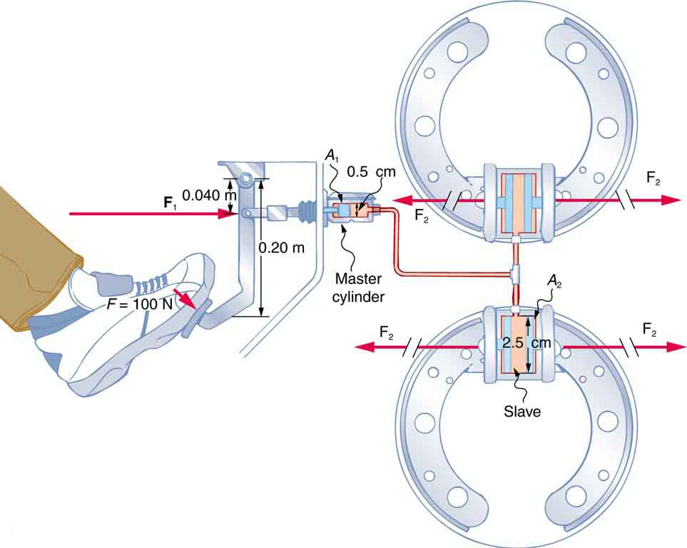
Example 11.6 Calculating Force of Slave Cylinders: Pascal Puts on the Brakes
Consider the automobile hydraulic system shown in Figure 11.14.
Figure 11.14 Hydraulic brakes use Pascal’s principle. The driver exerts a force of 100 N on the brake pedal. This force is increased by the simple lever and again by the
hydraulic system. Each of the identical slave cylinders receives the same pressure and, therefore, creates the same force output F 2 . The circular cross-sectional areas
of the master and slave cylinders are represented by A 1 and A 2 , respectively
A force of 100 N is applied to the brake pedal, which acts on the cylinder—called the master—through a lever. A force of 500 N is exerted on the
master cylinder. (The reader can verify that the force is 500 N using techniques of statics from Applications of Statics, Including Problem-
Solving Strategies.) Pressure created in the master cylinder is transmitted to four so-called slave cylinders. The master cylinder has a diameter
of 0.500 cm, and each slave cylinder has a diameter of 2.50 cm. Calculate the force F 2 created at each of the slave cylinders.
Strategy
We are given the force F 1 that is applied to the master cylinder. The cross-sectional areas A 1 and A 2 can be calculated from their given
F
diameters. Then
1
A = F 2 can be used to find the force F
1
A 2
2 . Manipulate this algebraically to get F 2 on one side and substitute known values:
Solution
F
Pascal’s principle applied to hydraulic systems is given by
1
A = F 2 :
1
A 2
2
(11.27)
F 2 = A 2
A F
1 1 = πr 2
πr 2 F 1 = (1.25 cm)2
1
(0.250 cm)2×500 N = 1.25×10⁴ N.
Discussion
This value is the force exerted by each of the four slave cylinders. Note that we can add as many slave cylinders as we wish. If each has a
2.50-cm diameter, each will exert 1.25×10⁴ N.
368 CHAPTER 11 | FLUID STATICS
A simple hydraulic system, such as a simple machine, can increase force but cannot do more work than done on it. Work is force times distance
moved, and the slave cylinder moves through a smaller distance than the master cylinder. Furthermore, the more slaves added, the smaller the
distance each moves. Many hydraulic systems—such as power brakes and those in bulldozers—have a motorized pump that actually does most of
the work in the system. The movement of the legs of a spider is achieved partly by hydraulics. Using hydraulics, a jumping spider can create a force
that makes it capable of jumping 25 times its length!
Making Connections: Conservation of Energy
Conservation of energy applied to a hydraulic system tells us that the system cannot do more work than is done on it. Work transfers energy, and
so the work output cannot exceed the work input. Power brakes and other similar hydraulic systems use pumps to supply extra energy when
needed.
11.6 Gauge Pressure, Absolute Pressure, and Pressure Measurement
If you limp into a gas station with a nearly flat tire, you will notice the tire gauge on the airline reads nearly zero when you begin to fill it. In fact, if there
were a gaping hole in your tire, the gauge would read zero, even though atmospheric pressure exists in the tire. Why does the gauge read zero?
There is no mystery here. Tire gauges are simply designed to read zero at atmospheric pressure and positive when pressure is greater than
atmospheric.
Similarly, atmospheric pressure adds to blood pressure in every part of the circulatory system. (As noted in Pascal’s Principle, the total pressure in a
fluid is the sum of the pressures from different sources—here, the heart and the atmosphere.) But atmospheric pressure has no net effect on blood
flow since it adds to the pressure coming out of the heart and going back into it, too. What is important is how much greater blood pressure is than
atmospheric pressure. Blood pressure measurements, like tire pressures, are thus made relative to atmospheric pressure.
In brief, it is very common for pressure gauges to ignore atmospheric pressure—that is, to read zero at atmospheric pressure. We therefore define
gauge pressure to be the pressure relative to atmospheric pressure. Gauge pressure is positive for pressures above atmospheric pressure, and
negative for pressures below it.
Gauge Pressure
Gauge pressure is the pressure relative to atmospheric pressure. Gauge pressure is positive for pressures above atmospheric pressure, and
negative for pressures below it.
In fact, atmospheric pressure does add to the pressure in any fluid not enclosed in a rigid container. This happens because of Pascal’s principle. The
total pressure, or absolute pressure, is thus the sum of gauge pressure and atmospheric pressure: P abs = P g + P atm where P abs is absolute
pressure, P g is gauge pressure, and P atm is atmospheric pressure. For example, if your tire gauge reads 34 psi (pounds per square inch), then the
absolute pressure is 34 psi plus 14.7 psi ( P atm in psi), or 48.7 psi (equivalent to 336 kPa).
Absolute Pressure
Absolute pressure is the sum of gauge pressure and atmospheric pressure.
For reasons we will explore later, in most cases the absolute pressure in fluids cannot be negative. Fluids push rather than pull, so the smallest
absolute pressure is zero. (A negative absolute pressure is a pull.) Thus the smallest possible gauge pressure is P g = − P atm (this makes P abs
zero). There is no theoretical limit to how large a gauge pressure can be.
There are a host of devices for measuring pressure, ranging from tire gauges to blood pressure cuffs. Pascal’s principle is of major importance in
these devices. The undiminished transmission of pressure through a fluid allows precise remote sensing of pressures. Remote sensing is often more
convenient than putting a measuring device into a system, such as a person’s artery.
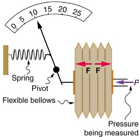
Figure 11.15 shows one of the many types of mechanical pressure gauges in use today. In all mechanical pressure gauges, pressure results in a
force that is converted (or transduced) into some type of readout.
CHAPTER 11 | FLUID STATICS 369
Figure 11.15 This aneroid gauge utilizes flexible bellows connected to a mechanical indicator to measure pressure.
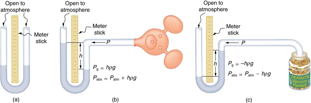
An entire class of gauges uses the property that pressure due to the weight of a fluid is given by P = hρg. Consider the U-shaped tube shown in
Figure 11.16, for example. This simple tube is called a manometer. In Figure 11.16(a), both sides of the tube are open to the atmosphere.
Atmospheric pressure therefore pushes down on each side equally so its effect cancels. If the fluid is deeper on one side, there is a greater pressure
on the deeper side, and the fluid flows away from that side until the depths are equal.
Let us examine how a manometer is used to measure pressure. Suppose one side of the U-tube is connected to some source of pressure P abs
such as the toy balloon in Figure 11.16(b) or the vacuum-packed peanut jar shown in Figure 11.16(c). Pressure is transmitted undiminished to the
manometer, and the fluid levels are no longer equal. In Figure 11.16(b), P abs is greater than atmospheric pressure, whereas in Figure 11.16(c), P abs is less than atmospheric pressure. In both cases, P abs differs from atmospheric pressure by an amount hρg , where ρ is the density of the
fluid in the manometer. In Figure 11.16(b), P abs can support a column of fluid of height h , and so it must exert a pressure hρg greater than atmospheric pressure (the gauge pressure P g is positive). In Figure 11.16(c), atmospheric pressure can support a column of fluid of height h , and so P abs is less than atmospheric pressure by an amount hρg (the gauge pressure P g is negative). A manometer with one side open to the
atmosphere is an ideal device for measuring gauge pressures. The gauge pressure is P g = hρg and is found by measuring h .
Figure 11.16 An open-tube manometer has one side open to the atmosphere. (a) Fluid depth must be the same on both sides, or the pressure each side exerts at the bottom
will be unequal and there will be flow from the deeper side. (b) A positive gauge pressure P g = hρg transmitted to one side of the manometer can support a column of fluid of height h . (c) Similarly, atmospheric pressure is greater than a negative gauge pressure P g by an amount hρg . The jar’s rigidity prevents atmospheric pressure from being transmitted to the peanuts.
Mercury manometers are often used to measure arterial blood pressure. An inflatable cuff is placed on the upper arm as shown in Figure 11.17. By
squeezing the bulb, the person making the measurement exerts pressure, which is transmitted undiminished to both the main artery in the arm and
the manometer. When this applied pressure exceeds blood pressure, blood flow below the cuff is cut off. The person making the measurement then
slowly lowers the applied pressure and listens for blood flow to resume. Blood pressure pulsates because of the pumping action of the heart,
reaching a maximum, called systolic pressure, and a minimum, called diastolic pressure, with each heartbeat. Systolic pressure is measured by
noting the value of h when blood flow first begins as cuff pressure is lowered. Diastolic pressure is measured by noting h when blood flows without
interruption. The typical blood pressure of a young adult raises the mercury to a height of 120 mm at systolic and 80 mm at diastolic. This is
commonly quoted as 120 over 80, or 120/80. The first pressure is representative of the maximum output of the heart; the second is due to the
elasticity of the arteries in maintaining the pressure between beats. The density of the mercury fluid in the manometer is 13.6 times greater than

370 CHAPTER 11 | FLUID STATICS
water, so the height of the fluid will be 1/13.6 of that in a water manometer. This reduced height can make measurements difficult, so mercury
manometers are used to measure larger pressures, such as blood pressure. The density of mercury is such that 1.0 mm Hg = 133 Pa .
Systolic Pressure
Systolic pressure is the maximum blood pressure.
Diastolic Pressure
Diastolic pressure is the minimum blood pressure.
Figure 11.17 In routine blood pressure measurements, an inflatable cuff is placed on the upper arm at the same level as the heart. Blood flow is detected just below the cuff,
and corresponding pressures are transmitted to a mercury-filled manometer. (credit: U.S. Army photo by Spc. Micah E. Clare\4TH BCT)
Example 11.7 Calculating Height of IV Bag: Blood Pressure and Intravenous Infusions
Intravenous infusions are usually made with the help of the gravitational force. Assuming that the density of the fluid being administered is 1.00
g/ml, at what height should the IV bag be placed above the entry point so that the fluid just enters the vein if the blood pressure in the vein is 18
mm Hg above atmospheric pressure? Assume that the IV bag is collapsible.
Strategy for (a)
For the fluid to just enter the vein, its pressure at entry must exceed the blood pressure in the vein (18 mm Hg above atmospheric pressure). We
therefore need to find the height of fluid that corresponds to this gauge pressure.
Solution
We first need to convert the pressure into SI units. Since 1.0 mm Hg = 133 Pa ,
(11.28)
P = 18 mm Hg× 133 Pa
1.0 mm Hg = 2400 Pa.
P g
Rearranging P g = hρg for h gives h = ρg . Substituting known values into this equation gives
CHAPTER 11 | FLUID STATICS 371
(11.29)
h =
2400 N/m2
⎛
⎛
⎝1.0×10³ kg/m3⎞⎠⎝9.80 m/s2⎞⎠
= 0.24 m.
Discussion
The IV bag must be placed at 0.24 m above the entry point into the arm for the fluid to just enter the arm. Generally, IV bags are placed higher
than this. You may have noticed that the bags used for blood collection are placed below the donor to allow blood to flow easily from the arm to
the bag, which is the opposite direction of flow than requi