,
.1)
с W + V
a
Where A is a coefficient: for high quality materials A=0.8, medium quality
– 0.75 and low quality – 0.65; V is volume of entrained air; C, W –
a
contents of cement and water, kg/m3; R –strength of cement, MPa.
c
146


Numerous experimental data shows, that there are a lot of factors besides
cement-water ratio (C/W), cement strength and aggregate quality such as
placeability of fresh concrete, hardening conditions, presence and quantity of
admixtures etc. which make influence on fine grained concrete strength.
Quality of the aggregate for fine grained concrete make much more influence
on its basic properties than those for conventional heavy concrete. According to
Y.Bagenov data replacement coarse sand for fine sand in concrete can reduce
strength for 25...30%, and sometimes in 2...3 times.
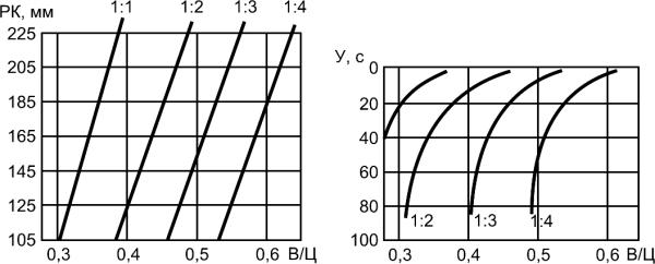
Concrete placeability parameter defines sand - cement ratio at given watercement ratio (Fig. 8.1).
147


FD, mm
P, seс
W/C
W/C
Fig. 8.1 Curves for selection of cement and medium coarseness sand
ratio, that provides given value of flow diameter (FD) and placeability (P)
of cement-sand mixtures (according to Y.M.Bagenov)
148


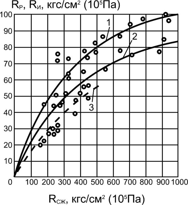
Raised tensile (flexural) strength and compressive strength ratio is distinctive
feature for fine grained concrete (Fig. 8.2).
Rt, Rf, МПа
10
9
Structure peculiarities make
8
influence on deformation
properties of fine grained concrete.
7
They have modulus of elasticity at
6
20...30% lower and higher
5
shrinkage and creep than ordinary
4
concrete. Deformability and creep
3
can be reduced considerably due
2
to the harshness of concrete mix,
application of force compacting
1
method.
10 20 30 40 50 60 70 80 90 100
Rcmp, МПа
Fig.8.2. Dependence of concrete flexural
strength (Rf) and tensile strength (Rt) on
compressive strength (Rcmp):
1 - Rf of sand concrete, 2 - Rf of ordinary
concrete, 3 – Rt of sand concrete
149


8.2. High-strength concrete
Until present there is no direct definition for the types of concrete, which
can be considered as high-strength ones. Conditional border between
conventional and high-strength concrete varies as concrete technology
develops. In the fifties of last century concrete grades 25-40 MPa
considered to be high-strength, in the sixties – 50-60 MPa. Now normally
high-strength concrete is ranged as concrete with compressive strength at
the age of 28 days 70-150 MPa. European standard EN206 envisage
possibility of concrete production and application including 115MPa
concrete grade. Mostly due to effective modifiers (superplasticizers and
silica fume) industrial technology of concrete production at given strength
range have been developed and appropriate standards were worked out.
Such concrete is used widely for load-carrying structures, monolithic
framework of high-rise constructions (Table 8.1), bridges, platforms,
vibrohydropressed tubes. There has been obtained concrete with
compressive strength up to 200 MPa.
150


Table 8.1
Examples of high-strength concrete application
at the high-rise buildings construction
Year
Number of
Concrete strength,
City
of construction
floors
MPa
Montreal 1984
26 119.6
Toronto 1986
68 93.6
New York
1987
72 57
Toronto 1987
69 70
Paris 1988
36 70
Chicago 1989
82 78
Guangow, China
1989
63 70
Chicago 1990
65 84
Frankfurt 1990
58 45
Seattle 1990
58 133
Frankfurt 1991
51 112
151


High-performance concrete is a type of high-strength concrete which has
compressive strength at the age of 2 days 30-50 MPa, at the age of 28 days –
60-150 MPa, frost resistance – more than 600 cycles of freezing and thawing,
water absorption – less than 1-2%, abrasiveness – no more than 0.3-0.4
g/cm2, adjustable deformability parameters.
Obtaining high strength of heavy concrete at high-strength aggregates is
possible due to increasing in concrete density and strength of cement stone
(cohesive factor) and contact zone (adhesive factor). The main direction of
high-strength concrete obtaining is providing extremely low water-cement ratio
(W/C) at comparatively high hydration degree of cement and necessary
compacting of concrete mix. At low W/C ratio obtaining of optimal ratio between
crushed stone and mortar content makes positive influence on concrete
strength.
Cardinal way of W/C ratio reduction without significant workability degradation
of concrete mix are superplasticizers (SP) adding. Unlike ordinary plasticizers
reducing water consumption up to 10-5%, superplasticizers permit to reduce
water consumption at 20-30% and more and to increase concrete strength.
Concrete with high early age strength can be obtained by regulation of SP
and W/C ratio. It can be increased in 2-3 times at adequately high dosage of
the admixture.
152


Concrete strength changes almost linearly with cement strength increasing.
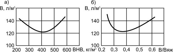
Binders of low water requirement (BLWR) obtained by fine milling of
portland cement clinker and mineral admixture with adding powdered
superplasticizer belongs to the effective binders for high-strength
concrete. BLWR have high specific surface (4000-5000 cm2/g), low water
requirement (16-20%) and strength up to 100 MPa. Water amount of
concrete mixes on the basis of binders of low water requirement (BLWR)
is lower at 35-50% than at the ordinary Portland cement (Fig.8.3).
A
B
W, l/m3
W, l/m3
BLWR,
W/C
kg/m3
Fig.8.3 Relationship between water amount of concrete mixes
(slump 1-4 cm) and BLWR content (A), water-cement ratio W/C (B)
153


In the fifties of the last century in Norway it has been suggested to improve
concrete properties by adding ultra fine byproducts of metallurgy industry –
silica fume (SF) and it have been started wide production of concrete with SF
since the middle seventies. It was found out that the most effective
microsilica admixtures are byproducts of crystalline silica and ferrosilicium.
They basically consist of amorphous silica (85-95% SiO ) in the form of
2
particles with diameter 0.1 mkm and have specific surface 1500-2000 m2/kg.
Silica fume adding to the concrete is effective in complex with
superplasticizer admixture taking into consideration increasing in mix water
requirement.
Also other ultra fine silica and aluminosilica materials can be effective in the
composition with superplasticizer.
154


8.3. Polymer-impregnated and
polymer-cement concrete
Polymer-impregnated concrete. Polymer-impregnated concrete is
concrete impregnated by polymer compositions or monomers with
subsequent polymerization. Polymer-impregnated concrete is included into
“P-concrete” group collecting different types of concrete where polymers
are used both as admixtures and basic components. Polymer-impregnated
concrete divides depending on impregnating material type: monomers
(styrene, methylmetacrylate etc.), viscous organic binders (bitumen,
paraffin etc.).
At concrete impregnation its structure changes, at first open capillary
porosity decreases drastically, cement stone and aggregate contact
zone is condensed. As a result water absorption reduces and
compressive strength and other mechanical properties increase
significantly.
155


There are shown comparison of the properties of ordinary initial concrete and
impregnated concrete at polymerization by metylmetacrylate (according to
Y.Bagenov data) in Table 8.2.
Table 8.2
Properties of ordinary initial concrete and polymer-impregnated concrete
Parameter
Initial concrete
Polymer-impregnated
concrete
Strength, MPa:
compressive
30...50
100...200
tensile
2...3
6...19
flexural
5...6
14...28
Modulus of elasticity at compression, MPa
2.5.104...3.5.104
3.5.104...5.104
Limit deformation at compression
0.001
0.002
Bond strength with reinforcement, MPa
1...2
10...18
Shrinkage
50.10–5
0...5.10–5
Creep
(40...60).10–5
(6...8).10–5
Electrical resistance, Om
105
1014
Water absorption, %
3...5
1
Frost resistance, cycles of freezing and
200
5000
thawing
Corrosive resistance to sulfates and acids
Insufficient
High
156


Polymer-cement concrete. Polymer-cement concrete is concrete modified
with polymer admixtures. Cresson had received first patent on application of
polymer cement with latex admixture in 1923.
Modified cement mixes differ from ordinary mixes due to their ability to water
keeping that increases when polymer-cement ratio increases. That permits to
improve placeability, prevent “drying” and reach good adhesion with porous
base.
One of the main results of polymer admixtures adding is tensile strength
increasing of cement concrete and their deformability. At adding of
polyvinylacetate (PVA) and latexes admixtures flexural strength increasing in
2-3 times. There is also observed increasing in limit extensibility and adhesion
to old concrete and reinforcement. PVA adding as an admixture to mortars
increases extensibility up to 2 times.
At selection of the application area of polymer-cement mortars and concrete
there are taken into consideration their specific properties and advantages
(Tab.8.3).
157


Table 8.3
Technical application areas of mortars and concrete modified by latex
(according to I. Okama)
Materials group
Materials assignment
Floors for public buildings, storages, administration buildings,
Floor coverings
shops, toilets
Road and abrasion
Crosswalks, stairs, railway platforms, road coverings
resistance coverings
Concrete flat roofs, masonry blocks, water cisterns, swimming
Watertight structures
pools, dikes for silage
Mortars for adhesion of finishing, heat-insulating and other
Binding compositions
materials;
Bonding new concrete to old one and new mortar to old one
Drainpipes, floors of chemical plants, mortars for acid resistant
Anticorrosive
tiles, basements for machinery, floors for chemical laboratories,
compositions
drug-store storages
Ship decks, bridges coverings, trains floors, coverings for
Toppings
pedestrian overpasses
158


8.4. Fiber reinforced concrete
Fibrous or fiber reinforced concrete is a group of composite materials
including short chopped fibers in cement matrix. There are different types of
fiber made of steel, glass, synthetic materials, asbestos, carbon etc.
For composite materials with discrete fibers modulus of elasticity (E) and
flexural strength (R ) can be approximately calculated from following:
fl
E=KrEfVf+EmVm, (8.2)
Rfl= KrRfVf+RmVm , (8.3)
Where K – reinforcement coefficient of concrete, E and E – modulus of
r
f
m
elasticity of fiber and matrix, R and R – flexural strength of fibers and
f
m
matrix, V and V – volume content of fibers and matrix.
f
m
159


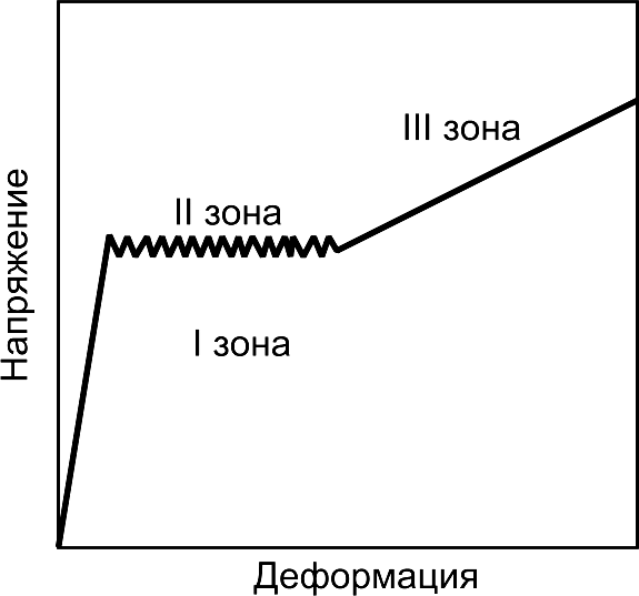
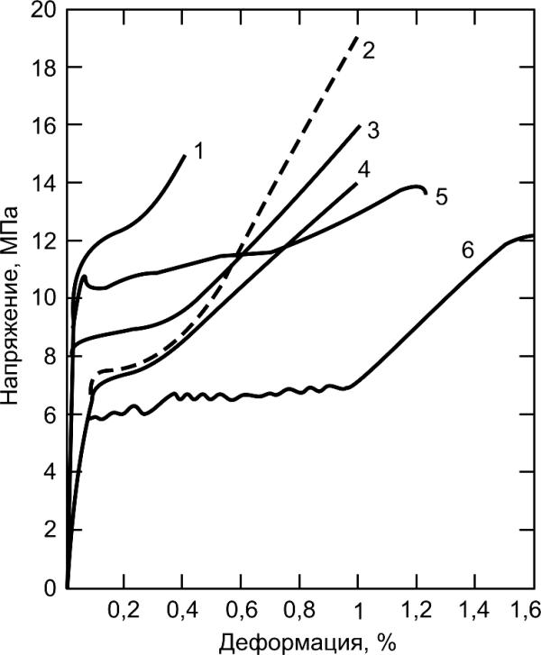
Typical stress – strain diagram of fibrous concrete consists of 3 zones (Fig.8.4, 8.5).
3 zone
2 zone
a
Stress
tress, MP
1 zone
S
Strain
Fig. 8.4. Typical curve of stress –
strain dependence for cement
Strain, %
compositions reinforced by fiber
Fig. 8.5. Curves of stress – strain dependences for
several fiber reinforced cement composites:
1 – Portland cement – steel wire, 1.5% by volume; 2 –
The same, 1% by volume, 3 – High-alumina cement –
fiberglass, 0.067% by volume; 4 – Portland cement –
zirconium fiberglass, 5% by volume; 5 – Portland cement
– polyamide fiber, 1.93% by volume; 6 –gypsum –
fiberglass, 1% by volume
160


At fibrous concrete destruction maximum work done at burst (W ) is expressed
b
by formula:
Wb=VfRflcr/12, (8.4)
Where R – flexural strength of fibers, V – volume content of fibers; l is
f
f
cr
critical length of fiber.
Steel fibrous concrete. Steel fibrous concrete is the most common fibrous
concrete on the basis Portland cement reinforced by steel fiber. Steel fiber is
presented usually by cuts of wire. Fibers can have different cross-area –
round, oval etc. with dimensions from 0.2 to 1.6 mm and length from 10 to 160
mm. Fibers surface can be sectional and smooth. Amount of added fibers
mostly varies from 0.5 to 2 % by volume. Adding into concrete steel fibers in
the amount of 1-1.5% by volume increases its tensile strength up to 100%,
flexural strength – up to 150-200%, compressive strength increases at 1025%.
161


Glass-fiber reinforced concrete. Along with steel fibrous concrete there is
positive experience of application of glass-fiber reinforced concrete (glass-fiber
reinforced cement) that allows reducing additionally weight of constructions.
Their production is based on adding into cement paste or cement mortar
alkaline-resistant fiber in the amount of 5% by mass. Tensile strength and
flexural strength of glass-reinforced mortar increases the strength of nonreinforced mortar in 2-3 times even after 10 years of air-dry hardening.
Maximum deformation caused by limit tensile stress in glass-reinforced mortar
is in 10 times more than in non-reinforced mortar.
There are combined successfully properties of initial materials and high
strength and durability is reached in the composites on the basis of mineral
binders reinforced by glass fiber.
Fiber made of non-alkaline aluminoborosilicate glass has the largest strength.
Alkaline oxides reduce strength of a fiber.
162

