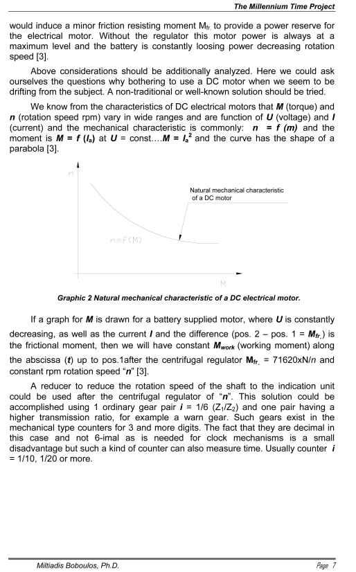
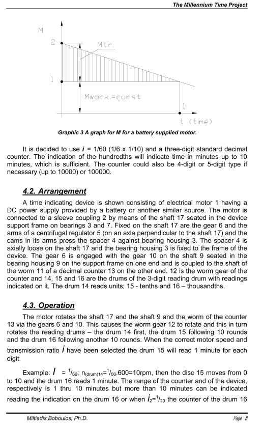
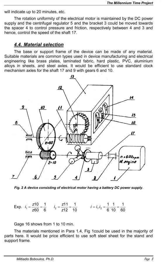
necessary uniformity and constant ωlevel. If I could only use such a motor the
electrical diagram would be very simple and supplied by a low-power battery and we would not have to use the pulsating electrical magnet wired in a much more complicated diagram with the reversible pendulum in the electrical clocks – like the ones used in cars [3].
What if the centrifugal regulator varies a forced resisting moment? This could be accomplished if some resistance is introduced caused by the friction of a washer on a fixed bracket and a rotating washer. Mfr.=F.μ.R, where F - force and R – radius. As the coefficient of friction μ (Note: could be f) does not change much with some minor changes in the speed, then it would be possible that the force and hence, the moment would be varied only by the pressing force F between two such washers. Such a design diagram could include one centrifugal regulator and use its arms to press the fractioning washers more or less and thus quickly change Mfr.
It is decided to use a centrifugal regulator providing constant rotation, as this seems to be an answer to the important issue of having a correct time reading. Varying the force of the spring pulling up the inertia weights towards the axis


