Once more a clock mechanism without the widely used anchor-balance stroke regulators. The idea is to use the kinetic energy of identical masses falling from identical heights – for example metal balls. They could also be used to rotate a blade wheel at the end of their free falling just like water stream in turbines [10].
This wheel could also be used as a mechanical stroke controller for the device provided the balls fall in equal intervals of time. It would be necessary to have a kinematical connection between a lever system and the blades of the impeller so when a ball falls and moves on another one is released at the top.
It would be necessary to install a bin (tank) for the metal balls in operation and another bin in front of this one for a back-up quantity ensuring continuous operation. Moving the balls from the bottom bin to the upper one should be by means of a DC electrical motor via a screw conveyor. It would be necessary to have a cyclic driving of the screw conveyor (elevator) including it in the kinematical circuit of an electric switch operated by the load of the heavy bottom bin when it is filled with balls [11]. The arrangement of this diagram seems to be rather simple. The blade wheel is connected via several gears to the dial and hands of an ordinary clock.
Such a time measuring device could be made with an attractive and novel looking appearance. We made the arrangement for the elevator – screw conveyor defining the cross-sectional shape of the vertical pipe so the spheres engaged in
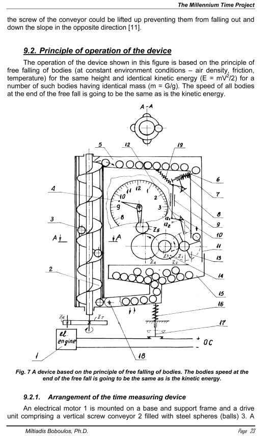
metal balls container 5 is located in the upper section and a vertical pipe 11 having an inner diameter larger than the diameter of the spheres (balls). Mounted across the upper end of the pipe 11 is a cutting device 6 with a spring 7 and arm 8, which is hinged to the stem 10 comprising two parts, connected by means of the nut 9. The stem 10 is hinged to another double-arm bar 12. An oblong cut is made in the bottom end of the pipe 11 where the vanes of a 4-vane (or 3-vane) wheel 13 are moving and the wheel 13 rotates around one central axle and is engaged via its gear Z1 with a gear transmission comprising the gears:
Z1 .Z2.Z3.Z4 . Z2 Z3 Z4 Z5