The uniform outflow off a tank could be used to build up a time measuring device. The idea belongs to our ancient predecessors who made the sand glass. This idea could be given a modern concept and thus apply it using liquids, for example water. We have observed water dripping of the tap uniformly filling vessels of identical volumes for equal intervals of time [12].
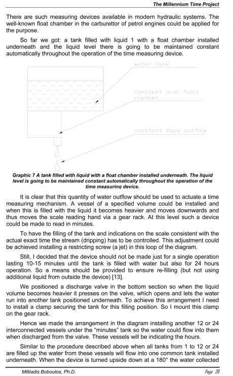
To have the water flowing out uniformly, which is the first and most important condition, we need to have constant pressure p (Pa). If I could think of some way of having constant pressure at the outlet of the tank, maybe using a motor driven pump or maintaining constant liquid level in the tank, then this will solve the question of the water regulator [12].
It seems the solution is maintaining a certain constant level in the tank.
 The Millennium Time Project
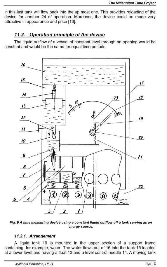
10 is positioned under 15 both connected by means of the pipe 12 having a flow control valve 11installed in it. The tank 10 is fixed to a gear rack 21, which is engaged with the gear 20 on the axle of the time indication hand 19 on a division scale 19. An opening closed by the valve 9 is provided in the bottom of the tank 10 and a spring 8 is provided under the tank 10. Tanks 6, 4, etc. up to 12 or 24 are provided under the tank 10 all connected by spout holes 5. The tanks 4, 6 …12 or 24 are one unit. Each has a valve 3 and a support lifting spring 2 or only a single one underneath. A tank 22 is located under these tanks, which is connected by means of a pipe to the tank 16. Indicating windows 1 are provided against the tanks 4, 6…. to 12 or 24.
11.2.2. OperationThe fluid from 16 flows into the lower tank 15 where the level is kept constant by means of the float 13 and the needle 14. The liquid flows out of 15 through the hole in the bottom and into the tank 10 where the flow rate is controlled by the flow control valve 11 so the tank 10 is filled up within a specified period of time, for example 60 minutes.
When 10 is full it becomes heavier and compresses the spring 8 and via the rack 21 and the gear 20 rotates the time indicating hand 19. When 10 is filled to the top it moves downwards, the valve 9 opens and the spring 23 holds the lighter tank 10 while the liquid flows out of it into the tank 6. Consecutively all tanks from 6 to 12…24 are filled up within 60 minutes, for example. When all these are filled in they press the springs 2 and open the valves 2 and then tanks 6, etc. are emptied similar to 10 above by means of another spring 23 attached to them. When the liquid flows into tank 22 the spring 23 under the hours tanks 6 releases them and they lift up closing the valves 2 and the procedure can then be repeated again. When the liquid in 22 is spent the whole device is turned upside down like a sand glass and re-filled again.