Performance Analysis of 2.5 Gbps GPON
S.Srinath
B.Tech , Department of ECE, Vellore Institute Of Technology, Vellore, Tamilnadu, India
ABSTRACT: The ITU-T G.984 is Gigabit-capable Passive Optical Networks (GPON) standard. In this paper, 2.5 Gb/s GPON link is presented. The quality or performance of a digital communication system is specified by its BER or Q value with respect to other parameters such as receiver sensitivity . The system performance is presented through various parameters such as Q factor, eye diagram. The proposed models have the nominal bit rate 2.5 Gbit/s with required bandwidth. It implemented using OptiSystem 7.0.
KEYWORDS: GPON, Bit Error Rate(BER), Q Factor, Eye Diagram.
I. INTRODUCTION
Fiber optics uses light signals to transmit data. As this data moves across a fiber, there needs to be a way to separate it so that it gets to the proper destination. A passive optical network does not include electrically powered switching equipment and instead uses optical splitters to separate and collect optical signals as they move through the network. A passive optical network shares fiber optic strands for portions of the network. Powered equipment is required only at the source and receiving ends of the signal. GPON (Gigabit Passive Optical Network) network consists of three important units ie Optical Line Terminal (OLT), Optical Network Unit (ONU) and Optical Splitters. The data is transmitted from the central office to a single optical fibre which runs from the central office to the optical splitters. This splitter then divides the power into N separate paths that goes to different subscribers. The number of splitting paths can vary from 2 to 64.Optical Line Terminal is a device that serves as the service provider endpoint of a passive optical network. It has two main functions: To perform conversion between the electrical signals used by the service provider’s equipment and the fiber optic signals used by the passive optical network. To coordinate the multiplexing between the conversion devices on the other end of that network (called Optical Network Units).Optical Network Unit is used in combination with an Optical Line Terminal (OLT). It is a device that terminates any one of the endpoints of a fiber to the premises network. It transforms incoming optical signals into electronics at a customer's premises. Optical Splitters are used to divide the incoming light beam from a single fiber into two or more fiber channels.GPON offers many advantages:It supports triple play service. It is a term for the provisioning of two bandwidth intensive service-high speed internet access and television and a less bandwidth demanding service, telephone over a single broadband connection.It has a high bandwidth transmission and long reach service coverage (20 km).Since PON uses the same fiber for upstream as well as downstream transmission, it utilizes WDM (Wave Division Multiplexing) for bidirectional transmission. It adopts two multiplexing techniques. In the downstream direction the data packets are transmitted in a broadcast manner. 1,490 nm wavelength is used for downstream traffic while in the upstream direction the packets are transmitted in a TDMA manner. The wavelength used for upstream traffic is 1310 nm. 1550 nm is reserved for overlay services, typically RF video (analog).
In this paper different characteristics like jitter, minimum Bit Error Rate (BER), Q factor and optical power for different wavelengths are compared. We will also see the variation of these factors when there is a change in the fiber attenuation.
II. RELATED WORK
While previous survey and research papers focussed on the downstream performance of a GPON system for data rates less than 2Gbps, this paper focuses on both the upstream and downstream performance of a GPON for data rate above 2Gbps ie 2.5Gbps(ITU-T G.984.1 standard).Higher data rate simulation is performed in this paper as high speed GPON network are the need of the hour. The performance measure of a GPON system presented in this paper analyses how the BER , Q-Factor and Optical power changes as wavelength and attenuation changes and how effective these factors are for better communication. The downstream performance analysis of GPON system is analysed for ‘single user’ case and ‘multiple user’ case. The upstream performance analysis of GPON system is analysed for ‘multiple user’ case. For analysing the performance of multiple user GPON system ‘BiDirectional Optical Fibres’, ‘BiDirectional Circulators’ and ‘BiDirectional Splitters’ available in Optisystem 7.0 software were used.
III. THEORY
Bit Error Rate (BER) is defined as the number of bit errors is the number of received bits of a data stream over a communication channel that has been altered due to noise, interference, and distortion or bit synchronization errors. BER is the number of bit errors divided by the total number of transferred bits during a studied time interval ie ( )  where E(t) is the number of bits received in error over time t, and N(t) is the total number of bits ( ) transmitted in time t. BER is a unit less performance measure, often expressed as a percentage.Q Factor describes how under damped an oscillator or resonator is. Higher Q factor indicates a lower loss of energy.Higher Q indicates a lower rate of energy loss relative to the stored energy of the resonator. A high-Q tuned circuit in a radio receiver would have more selectivity and hence better job of filtering out signals from other stations that lie nearby on the spectrum.Eye Diagram patterns are a widely used tool for studying the quality and stability of optical communication systems. The quality of the signals can be judged from the appearance of the eye. It is an experimental tool for the evaluation of the combined effects of channel noise and inter symbol interference on the performance of a baseband pulse-transmission system. It is the synchronized superposition of all possible realizations of the signal of interest viewed within a particular signaling interval. It is a composite view of all the bit periods of a captured waveform superimposed upon each other. If the bottom appears to have a smaller amplitude variation than the top, the signal seems to carry more 0s than 1s.
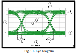
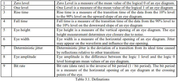
The following can be obtained from an eye diagram.
IV. OVERVIEW OF GPON SYSTEM
Recommendation ITU-T G.984.1 describes a flexible optical fibre access network capable of supporting the bandwidth requirements of business and residential services and covers systems with nominal line rates of 2.4 Gbit/s in the downstream direction and 1.2 Gbit/s and 2.4 Gbit/s in the upstream direction. Both symmetrical and asymmetrical (upstream/downstream) gigabit-capable passive optical network (GPON) systems are described.GPON standard defines a lot of different line transmission rates for downstream and upstream direction.

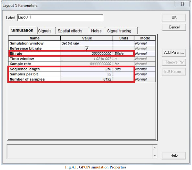
The simulation was performed for a bit rate of 2.5Gbps.
V. SIMULATION DESIGN, MODELING & RESULTS AND DISCUSSION
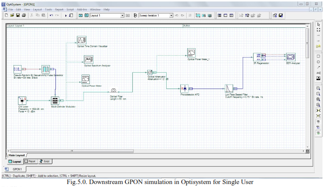
The proposed 2.5 Gbps simulation model of GPON was done in optisystem software.The model was designed for a ‘single user’ scenario and a ‘multiple user’ scenario. It consist of pseudo random sequence generator, NRZ pulse generator, continuous wave laser source, Mach-Zehender modulator, It also has an ONT receiver should have photodiode, low pass filter,3R generator, BER analyzer, Bessel optical fiber filter. The link, sometimes called channel, is consists of 20 km/50km of single mode fiber SMF28 and optical attenuator so as to add the loss for all the ODN class.
SINGLE USER :
CASE 1:
In CASE 1 , the wavelength of 1490 nm was chosen with a fibre length of 50km and fibre attenuation of 0.7db/km.
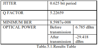
In figure 5.1 an open eye pattern is obtained which indicates less jitter and signal distortion. Figure 5.2 represents the Q factor which is high and its sharp graph indicates low loss. Figure 5.3 indicates the BER which is less. The optical power at the end of the fiber through which the signal has been transmitted has reduced from 6.75 dBm to -29.418 dBm.
CASE 2:
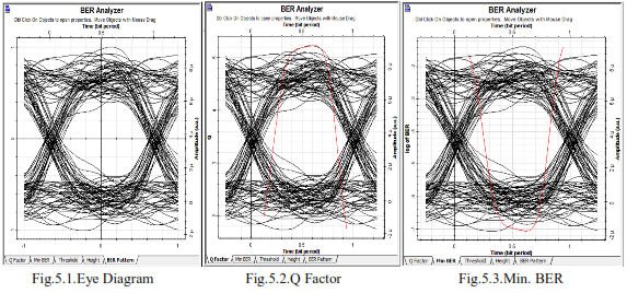
In CASE 2 , the wavelength of 1699.983 nm was chosen with a fibre length of 50km and fibre attenuation of 0.6db/km.

Table.5.2. Results
Figure 5.4 has more number of amplitude variation at the one level than the zero level. Hence there are more number of one’s in the signal than zero’s. Figure 5.5 represents the Q factor which is around 20. Figure 5.6 indicates the BER which is low. The optical power at the end of the fiber through which the signal has been transmitted has reduced from 6.785 dBm to -24.501 dBm.
CASE 3:
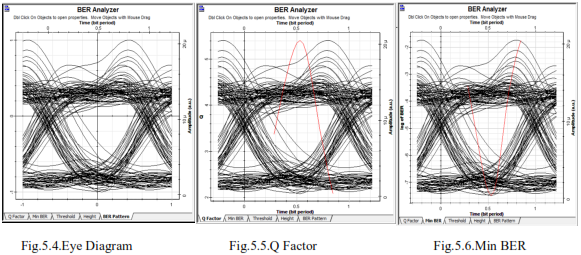
In CASE 3 , the wavelength of 1700 nm was chosen with a fibre length of 50km and fibre attenuation of 0.2db/km.
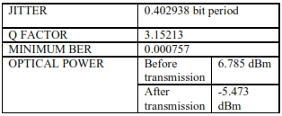
Table.5.3. Results
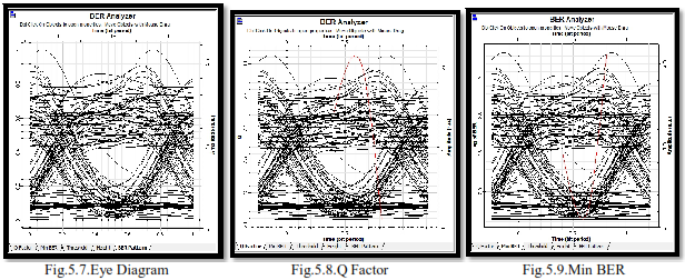
In figure 5.7 the eye opening is very small indicating lot of noise and crosstalk in the signal. Figure 5.8 represents the Q factor which is low. Figure 5.9 indicates the BER which too has increased from the previous cases. The optical power at the end of the fiber through which the signal has been transmitted has reduced from 6.785 dBm to -5.473 dBm.
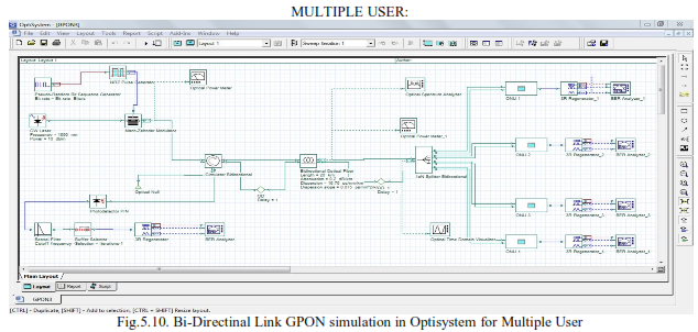
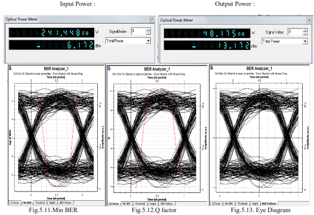
The wavelength of 1550 nm was chosen with a fibre length of 20km and fibre attenuation of 0.2db/km.

In figure 5.11 an open eye pattern is obtained which indicates less jitter and signal distortion. Figure 5.12 represents the Q factor which is high and its sharp graph indicates low loss. Figure 5.13 indicates the BER is less. The optical power at the end of the fiber through which the signal has been transmitted has reduced from -6.172 dBm to -13.172 dBm.
VI. CONCLUSION
SINGLE USER - From the graphs we can see that as the wavelength is changed from 1490 nm to 1700 nm the eye diagram changes. In the first case i.e. 1490 nm an open eye pattern is obtained which indicates less jitter and signal distortion. The Q factor is high and its sharp graph indicates low loss. Also the BER is less. The optical power at the end of the fiber through which the signal has been transmitted has reduced from 6.75 dBm to -29.418 dBm.
The second case 1699.983 nm has more number of amplitude variation at the one level than the zero level. Hence there are more number of one’s in the signal than zero’s. The jitter has increased from the previous cases. The Q factor has reduced to a mere 20 and there is a small BER too.
In the third case of 1700 nm, the eye opening is very small indicating lot of noise and crosstalk in the signal. There is a huge amount of jitter and it has a very low Q factor. The BER too has increased from the previous cases. Thus performance of the network is best obtained at a wavelength of 1490 nm.
MULTIPLE USER USING BIDIRECTIONAL LINK - From table 5.4,the wavelength was chosen to be 1550 nm in which Q factor was found out to be around 6 for the ‘Optical network units’ and the BER was found out to be 10^-12. Similarly for the uplink Q factor was found out to be around 6 for the ‘OLT’ and the BER was found out to be 10^-8. Thus, we see that the Q factor and the BER was exceptionally good for the GPON system operating at a wavelength of 1550nm and an input power of 10dbm using an optical fibre of length 20km with an attenuation of 0.2db/km.
VIII. ACKNOWLEDGEMENT
At the outset, I would like to express my gratitude for my institute – Vellore Institute of Technology (V.I.T.) for providing me with the opportunity to undergo my undergraduate training, and assimilate knowledge and experience hitherto unknown to me. I would like to sincerely thank my teacher, Prof. Revathi.S - Assistant Professor(Selection Grade), for her constant support during the course of my activities. I will forever be obliged to madam for her assistance, encouragement and guidance.
REFERENCES
[1] X. Z. Qiu, J. Vandewege, F. Fredricx, and P. Vetter, “Burst Mode Transmission in PON Access Systems”, 7th Eur. Conf. networks Optical Communication, pp.127–132,2002.
[2] Xing-Zhi Qiu,“Development of GPON Upstream Physical-Media-Dependent Prototypes,” Journal of Lightwave Technology,Vol.22, Issue.11, pp.2498 – 2508,2004.
[3] P. Vetter ,“Study and Demonstration of Extensions to the Standard FSAN BPON” ,Int. Symp. Services Local Access,pp.119–128, 2002.
[4] ITU-T recommendation G.984.1, “Gigabit-capable Passive Optical Networks (GPON): General Characteristics”, International Telecommunication Union, March 2003.
[5] ITU-T Recommendation G.984.2, “Gigabit-capable Passive Optical Networks (G-PON): Physical Media Dependent (PMD) layer specification”, International Telecommunication Union, March 2003.
[6] ITU-T Recommendation G.975, “Forward error correction for Submarine systems”, International Telecommunication Union, Oct. 2000.
[7] ITU-T recommendation G.984.4, “Gigabit-capable Passive Optical Networks (GPON): ONT management and control interface specification”, International Telecommunication Union, June 2004.
[8] Bakarman H.A. ,Shaari . S, Ismail.M , “Simulation of 1.25 Gb/s downstream transmission performance of GPON-FTTx”, International Conference on Photonics (ICP), pp. 1 – 5, 2010
[9] V. Alwayn, “Optical Network Design and Implementation”, Cisco Press,2004.
[10] J. H. Franze and V. K. Jain, “Optical Communications: Components and Systems”, Narosa Publishing House, 2000.
[11] T. Antony and A. Gumaste,“WDM Network Design”, Cisco Press, ch. 4,2003.
[12] Lallukka, Sami & Raatikainen,“Pertti. Passive Optical Networks. Transport concepts”, Espoo,2006.
[13] F. J. Effenberger and E. Shraga,“Status of GPON and B-PON standards”, Flexlight-networks,2004.
BIOGRAPHY


 where E(t) is the number of bits received in error over time t, and N(t) is the total number of bits ( ) transmitted in time t. BER is a unit less performance measure, often expressed as a percentage.Q Factor describes how under damped an oscillator or resonator is. Higher Q factor indicates a lower loss of energy.Higher Q indicates a lower rate of energy loss relative to the stored energy of the resonator. A high-Q tuned circuit in a radio receiver would have more selectivity and hence better job of filtering out signals from other stations that lie nearby on the spectrum.Eye Diagram patterns are a widely used tool for studying the quality and stability of optical communication systems. The quality of the signals can be judged from the appearance of the eye. It is an experimental tool for the evaluation of the combined effects of channel noise and inter symbol interference on the performance of a baseband pulse-transmission system. It is the synchronized superposition of all possible realizations of the signal of interest viewed within a particular signaling interval. It is a composite view of all the bit periods of a captured waveform superimposed upon each other. If the bottom appears to have a smaller amplitude variation than the top, the signal seems to carry more 0s than 1s.


