Design and Electromagnetic Modeling of E-Plane Sectoral Horn Antenna For Ultra Wide Band Applications On WR-137 & WR-62 Waveguides
S.Srinath
(Final Year Student,ECE, Vellore Institute of Technology, Vellore, India)

ABSTRACT : The Design and EM modeling of a E-Plane Sectoral Horn Antenna for Ultra Wide Band Application on WR-137 and WR-62 standard waveguides are presented in this paper. In E-plane sectoral antenna, the E-Plane is much narrower as the flaring and dimensions of the horn are much greater in that direction. The horn flare angle, horn size, wall thickness, etc of the E-plane sectored horn antenna are examined. The return loss, input impedance, total gain and field pattern of the E-plane sectored horn antenna are observed. The antenna is simulated using ANSOFT HFSS 14.0.
KEYWORDS : Ansoft HFSS Simulator, Beam width, Directivity, E-Plane Horn Antenna, Electromagnetic modeling, Radiation Pattern, Return Loss
I. INTRODUCTION
An antenna is an electrical device which converts electric currents into radio waves, and vice versa. To transmit the signal a transmitter applies an oscillating radio frequency electric signal to the antenna’s terminals, and the antenna radiates the energy in the form of electromagnetic waves.Horn antennas are used as antennas at UHF and microwave frequencies, above 300 MHz. They are used as feeders for larger antenna structures such as parabolic antennas. Over the hundred years, horn antennas have given the best directive and high power operation for Microwave Frequencies. Design Simplicity and large gain with best matching properties are added advantage of Horn antenna. Applications include Radar, Satellite tracking, Radio astronomy and Communication dish antennas. Other applications are Reflector feeds, Gain standards for antenna measurements, EMC/EMI tests, Communication systems, Direction finding (DF), mm-wave systems.
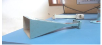
Fig 1 : A Practical Horn Antenna
A E-plane sectoral horn is one in which the opening is flared in the direction of the E-field.
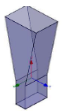
Fig 2 : E-Sectored Horn Antenna
The E-Plane sectored horn antennas are chosen because of their directional radiation pattern, ability to achieve high gain and directivity, and their ease of fabrication. The horn antenna which is designed was subject to the following constraints:
II. ANTENNA DESIGN
The C and Ku frequency bands were selected as the operating frequency. These bands are selected as they pertain to the communication frequency bands. The design was performed to accomplish an ultrawide bandwidth. (i) For the first case of 8Ghz (C Band) the operating frequency was chosen to be 8Ghz. The waveguide dimensions are a = 34.85mm, b = 15.8mm, waveguide length = 31.75mm. These indicate the standard WR-137 waveguide. Horn size dimensions are b=44.45mm, horn flare length = 95.25mm, wall thickness = 1.626mm. (ii) For the second case of 16Ghz (Ku Band) the operating frequency was chosen to be 16Ghz. The waveguide dimensions are a = 15.8mm, b = 7.9mm, waveguide length = 15.88mm. These indicate the standard WR-62 waveguide. Horn size dimensions are b=22.23mm, horn flare length = 47.63mm, wall thickness = 1.016mm. For both the cases the outer boundary condition is Radiation Boundary Condition. The Radiation Boundary Condition are as follows :
In HFSS to properly model the far field behavior of an antenna, an appropriate volume of air must be included in the simulation. Truncation of the solution space is performed by including a radiation boundary condition on the faces of this air volume that mimics free space. The appropriate distance between strongly radiating structures and the nearest face of the air volume depends upon whether a radiation boundary condition is used. HFSS also uses Finite Element Method (FEM) as analysis & solution to Electromagnetic problems by developing technologies such as tangential vector finite elements, adaptive meshing, and Adaptive Lanczos-Pade Sweep (ALPS).
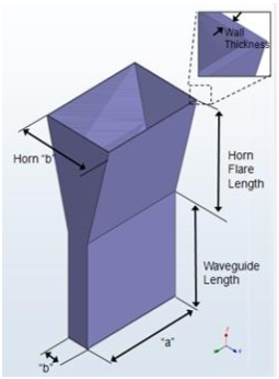
Fig 3 : Structure of the proposed E-Plane Horn Antenna
III. PROPOSED MODEL IN ANSOFT HFSS 14.0 FOR CASE 1
The 3D view of the designed E-Plane Horn Antenna in HFSS for a solution frequency of 8Ghz (C-Band ) is shown below. The boundaries for the air-box are set as an ideal propagation space and and the ground plane as perfect electric conductor.
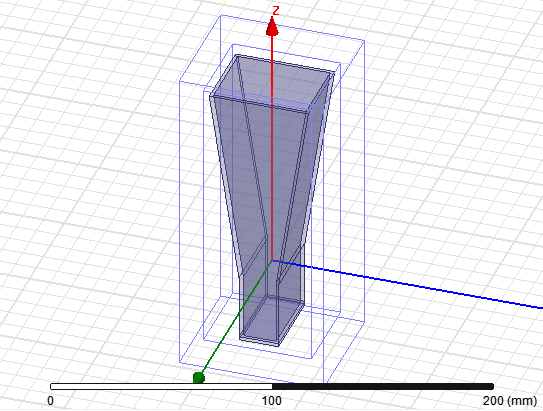
Fig 4 : 3D View of the E-Plane Horn antenna in HFSS for a solution frequency of 8Ghz
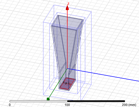
Fig 5 : Figure showing the direction of excitation for a solution frequency of 8Ghz
IV. RESULTS AND DISCUSSION FOR CASE 1
The parameters which verify the success of antenna design are beam width, impedance matching , etc. These are analysed here. The gain of the antenna versus frequency with return loss is -44dB at 8Ghz is shown below.
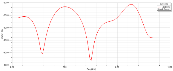
Fig 6 : Return loss in db over frequency range for a solution frequency of 8Ghz
The Radiation pattern for the antenna design in 3D is shown in below.
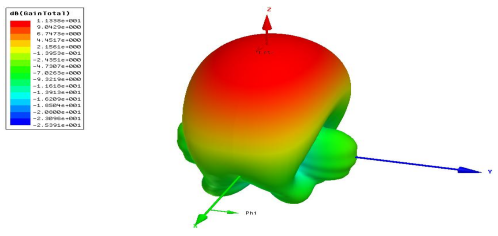
Fig 7 : 3D Radiation pattern of the antenna in HFSS for a solution frequency of 8Ghz
The 2D plot is total gain for phi = ‘0 deg’ and phi = ’90 deg’ is shown below.
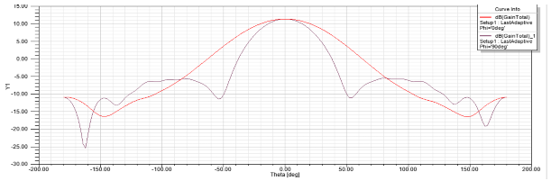
Fig 8 : 2D Plot for total gain versus theta (deg) with phi for a solution frequency of 8Ghz
V. PROPOSED MODEL IN ANSOFT HFSS 14.0 FOR CASE 2
The 3D view of the designed E-Plane Horn Antenna in HFSS for a solution frequency of 16Ghz (Ku-Band ) is shown below.
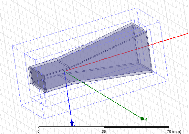
Fig 9 : 3D View of the E-Plane Horn antenna in HFSS for a solution frequency of 16Ghz
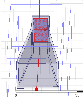
Fig 10 : Figure showing the direction of excitation for a solution frequency of 16Ghz
VI. RESULTS AND DISCUSSION FOR CASE 2
The parameters which verify the success of antenna design are beam width, impedance matching , etc. These are analysed here. The gain of the antenna versus frequency with return loss is -49dB at around 16 Ghz is shown below.
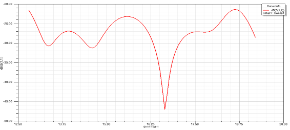
Fig 11 : Return loss in db over frequency range for a solution frequency of 16Ghz
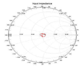
Fig 12 : The range of input impedance is shown below for a solution frequency of 16Ghz
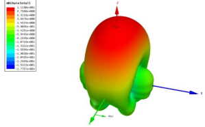
Fig 13 : 3D Radiation pattern of the antenna in HFSS for a solution frequency of 16Ghz
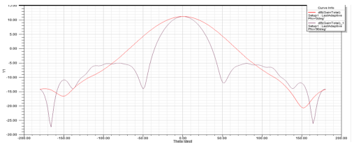
Fig 14 : 2D Plot for total gain versus theta (deg) with phi for a solution frequency of 16Ghz
VII. CONCLUSION
An Ultra Wide Band E-Plane sectored Horn Antenna operating at solution frequencies of 8Ghz and 16Ghz frequency range was designed. The horn antenna which was designed satisfied the following constraints: (i)Operating frequency around 8 GHz (C Band) for first case and 16 GHz (Ku Band) for second case; (ii)Maintain a gain of 10 dB over the entire operating frequency range. The return loss for both the cases was found to be greater than -40db.Thus the desired results are achieved and the simulated structures are suitable for various applications.
At the outset, I would like to express my gratitude for my institute – Vellore Institute of Technology (V.I.T.) for providing me with the opportunity to undergo my undergraduate training, and assimilate knowledge and experience hitherto unknown to me.
REFERENCES
[1] Lei Yang, Weihua Tan, Zhongxiang Shen, and Wen Wu, WideBand Wide-Coverage Linear Array of Four Semi-Circular Sector Horns, IEEE transactions on antennas and propagation, vol. 60, no.8, August 2012.
[2] Thomas A Milligan, Modem Antenna Design (John Wiley & Sons INC, Second Edition.)
[3] Constantine. A. Balanis, Antenna Theory Analysis & Design (John Wiley, & Sons INC, Third Edition.)
[4] M. M. Tentzeris, J. Laskar, J. Papapolymerou, S. Pinel, V. Palazzari, R. Li, G. DeJean, N. Papageorgiou, D. Thompson, R.Bairavasubramanian, S. Sarkar, and J.-H. Lee, 3D Integrated RF and millimeter-wave functions and modules using liquid crystal polymer (LCP) system-on-package technology, IEEE Trans. Adv. Packag., vol. 27, no. 2, pp. 332–340, May 2004.
[5] D. M. Pozar and D. H. Schubert, Microstrip Antennas—The Analysis and Design of MicrostripAntennas and Arrays (New York: IEEE Press, 1995.)
[6] F.Mohamadi Monavar , N.Komjani and P.Mousavi, Application of Invasive Weed Optimization to design a broadband Patch antenna with symmetric radiation Pattern, IEEE antennas and wireless propagation letters,Vol.10,2011.
[7] Qi wu ,ronghong jin, and junping geng, A Single layer ultrawideband microstrip antenna , IEEE antennas and wireless propagation letters,vol.1,January 2010.
[8] A. W. Love , Antenna Engineering Hand book (R. C. Johnson and H. Jasik, Ed. New York, 1984.)
BIOGRAPHY

S.SRINATH passed 10th C.B.S.E. Board with a mark of 475/500(95%) and 12th C.B.S.E. Board from D.A.V. Boys Senior Secondary School, Gopalpuram, Chennai ,India with a mark of 458/500(91.6%).Currently he is studying final year B.Tech, ECE, School of Electronics Engineering in Vellore Institute of Technology , Vellore, India.

Reads:
110
Pages:
36
Published:
Apr 2023
“IntroductionWith a few poor decisions, your life may veer off-track. One thing leads to another, and suddenly you realize you’re unable to live the life you ...
Formats: PDF, Epub, Kindle, TXT

Reads:
192
Pages:
86
Published:
Nov 2022
Social media marketing can be automated. It can be mastered to the point where it can produce income after you've set it. You need to be visible on the four m...
Formats: PDF, Epub, Kindle, TXT

Reads:
17
Pages:
30
Published:
Aug 2022
In this guide, we’re sharing 15 marketing tips for lawyers to keep their law firms relevant, cut through the competition, and draw in even more clients in 202...
Formats: PDF, Epub, Kindle, TXT

Reads:
114
Pages:
191
Published:
Mar 2020
Main author Ravi S. Iyer created the eklavyasai.blogspot.com blog and used it mainly from September 2011 to end 2014 to play a part-time, peaceful and amicab...
Formats: PDF, Epub, Kindle, TXT