While I am not a radio frequency (RF) engineer, I have had a lot of practical experience setting up 802.11b networks. There isn't nearly enough room here for a full examination of the nuances of radio frequency communications. For more authoritative sources, be sure to check out the great resources in Appendix A—notably, the fantastic publications put out by the American Radio Relay League (AARL), an association of amateur radio operators. Radio is an entire field of study unto itself.
Antenna selection has a tremendous impact on the range and usability of your wireless network. Ironically, the design of almost every external 802.11b card puts the antenna in the worst possible orientation: sideways and very close to the laptop (or desktop). In this position, the radiation pattern is almost straight up and down! Not only does this drive half your signal into the table, it leaves your poor, underpowered radio susceptible to interference from the computer itself.
The one notable exception to this state of affairs is Apple's built-in AirPort card. They've thought enough to include an internal antenna connector that runs up the LCD panel. This is an excellent design with much better range, although it does preclude adding an external antenna. It looks like IBM is the first to play copycat with their i Series ThinkPads as well.
You will see a tremendous difference in signal strength by attaching a small omnidirectional external antenna to your client card and orienting it properly. Which way is properly? That depends on your environment. Try every possible position, with your signal strength meter open. I've put mine on top of my monitor, below the desk, sideways, on the table behind me, and even slung over my shoulder. The best orientation of your antenna is always in the position in which it receives the best signal, so don't be afraid to move the antenna around.
If you're in a pinch without an external antenna, you can watch the wonders of RF by opening up your strength meter and tilting your laptop sideways. Watch that signal bar grow. Go for the green! Learn to type sideways! Better yet, redesign your network to extend your range, and always pack a spare external antenna.
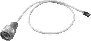
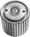
Before looking at adding antennas to your network, make sure your card can take an external antenna. Many low-priced cards don't include external connectors anymore. You will have trouble finding a connector to fit the ones that do, as every manufacturer provides its own proprietary connector (see Figure 6-6). Check out your friendly local radio supplier for proprietary-to-standard adapters, although they tend to be overpriced.
Figure 6-6. The infamous Lucent Pigtail adapter, list price $80
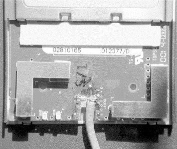
Of course, if you have good tools and moderate soldering skill, you may have luck making your own adapter, similar to the one shown in Figure 6-7. Why spend $80 on a ridiculous proprietary connector when you can make your own in a few minutes?
Figure 6-7. A do-it-yourself adapter: $3
The hack-it-in approach is really only practical for a fixed, point-to-point link, as there is no strain relief on the joint. As time marches on, bulk discounts for proprietary-to-standard pigtails are becoming more common. You shouldn't have to spend more than $20-30 per adapter if you can buy in quantity from a third party. Remember to buy the shortest cable you can use to minimize signal loss in the cable (see the discussion later in this chapter on choosing cable).
Pigtails are manufacturer- (and even model number-) specific, so be sure that you are getting the correct pigtail for the card you intend to use it with. Also, because PCMCIA cards have limited space for connectors, the pigtail plugs tend to be tiny and very fragile. One good tug will ruin your pigtail, connector, or both. You have been warned! (Not that I would personally know how easy they are to break. Not even at 2:00 A.M. after too much espresso and too many hours staring at the screen, trying to make a deadline. No sir.)
However you attach your antenna to your radio, always look for a way to position your equipment so it can see the antenna at the other end. This is called having line of sight (LOS) to the other node. While it helps on short links (such as from your laptop to your access point), it is absolutely critical on long-distance point-to-point links. The ideal path between two antennas would be on towers well above any ground clutter, with a valley in between, pointed directly at each other. This is hardly ever the case, but try to get as close to this ideal as possible.
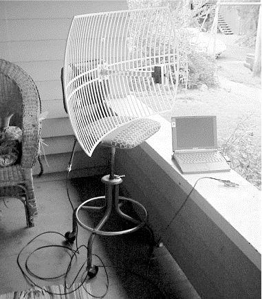
For outdoor applications, trees are probably going to be your single biggest signal killer (followed by metal, wet masonry, and other 2.4GHz gear). When choosing a place to locate your antenna, consider how changes in the environment will affect your link (what looks like the perfect place in the winter may be completely obscured by leaves in the spring!). Walk around the space you have available, and try to find the best possible place for the antenna. Don't just assume that the highest point is the place to install it. After trying every spot on my roof (in vain) to find line of sight to O'Reilly, I got down and sat on my front porch in frustration. It was then that I noticed that I could see the building, about half a mile away, with nothing in between. Setting the antenna on a tripod on my porch, I instantly got a solid signal. Lesson learned: the right place for the antenna is different in every installation.
6.2.1 AntennasAntennas do not give you more signal than you started with (that's what amplifiers are for). What they do is focus the available signal in a particular direction, like turning the focus head of a flashlight. It doesn't make the bulb any brighter, it just focuses what you have into a tighter space. Focusing a flashlight gives you a brighter beam that covers a smaller total area, and, likewise, more directional antennas give you a stronger perceived signal in a smaller area. All antennas are somewhat directional, and the measure of their directionality is referred to as gain. Typically, the higher the gain, the better the range (in the direction that the antenna radiates best in).
There are four different general types of antennas suitable for 2.4GHz use. Each works well for its own application, and no single antenna works best for every application. Plan ahead of time what your goals are, and configure your network to meet those goals. The following sections describe the most common types of antennas, listed in rough order of increasing directionality.
6.2.1.1 OmniOmnidirectionals (or omnis), shown in Figure 6-8, radiate outward in all horizontal directions roughly equally. Imagine putting an enormous donut around the center pole of an omni. That is what the radiation pattern looks like. These are good for covering a large area where you don't know which direction your clients might come from. The downside is that they also receive noise from every direction, so they typically aren't as efficient as more directional antennas.
Figure 6-8. Omnis range from tiny extenders to building-mounted poles
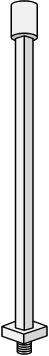
They look like tall, thin poles, anywhere from one to five feet long, and they tend to be expensive. The longer they are, the more elements they have (and usually more gain and higher price). They are mounted vertically, like a popsicle stick reaching skyward. They gain in the horizontal, at the expense of the vertical. This means that the worst place to be in relation to an omni is directly beneath (or above) it. The vertical response improves dramatically as you move away from the antenna.
6.2.1.2 SectorPicture an omni with a mirror behind it, and you'll have the radiation pattern of a sector (or sectoral) antenna. Sectors radiate in one direction, with a beam as wide as 180 degrees, or as narrow as 60 degrees (or even less). They excel in point-to-multipoint applications, where several clients access the wireless network from the same direction.
Sector antennas (shown in Figure 6-9) come in a variety of packages, from flattened omnis (tall, thin, and rectangular) to small, flat squares or circles. Some are only eight inches across and mount flat against a vertical wall or on a swivel mount. They can also be ceiling mounted to provide access to a single room, like a meeting room, classroom, or tradeshow floor. As with omnis, cost is usually proportional to gain.
Figure 6-9. Sector antennas tend to be flat and thin
 6.2.1.3 Yagi
A yagi looks like an old television aerial. It is either a flat piece of metal with a bunch of horizontal crosspieces or a long pipe with bunch of washers along its length (see horizontal crosspieces or a long pipe with bunch of washers along its length (see 10). The typical beam width can vary from 15 degrees to as much as 60, depending on the type of antenna. As with omnis, adding more elements means more gain, a longer antenna, and higher cost.
Figure 6-10. A Yagis come in various shapes, but all have multiple elements
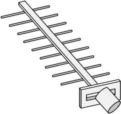
Some yagis are simply bare, like a flat Christmas tree pointed vaguely in the direction of communications. Others are mounted in long, horizontal PVC cans. They can work well in point-to-point or point-to-multipoint applications, and usually they can achieve higher gain than sectors.
6.2.1.4 Parabolic dishIn some ways, a dish is the opposite of an omni. Rather than trying to cover the entire area, a dish focuses on a very tight space (see Figure 6-11). Dishes typically have the highest gain and most directionality of any antenna. They are ideal for a point-to-point link and nearly useless for anything else.
Figure 6-11. A 24dB parabolic dish
Dishes can be solid or mesh, as small as 18 inches across or as big as you like (a 30-foot dish is possible, but probably not very convenient). A dish that can send an 802.11b signal more than 20 miles can be as small as a few feet across. In terms of gain for the buck, dishes are probably the cheapest type of antenna. Some people have been successful in converting old satellite and DSS dishes into 2.4GHz dishes; see Appendix A for links.
One other property of antennas worth mentioning here is polarization. The polarization of an antenna refers to the direction that the electrical part of the electromagnetic wave travels in. Both horizontal and vertical polarizations are common, but in some exotic antennas, circular (clockwise or counterclockwise) polarization is possible. The polarization of the antenna on each end of a link must match, or the radios will have trouble talking to each other. Omnis and sectors are vertically polarized. Yagis and dishes can be mounted vertically or horizontally, depending on the application. On a point-to-point link, try both and see which incurs the lowest noise. The polarization of a dish is indicated by the position of the receiving element, not the rear reflector (so an oval dish that goes up and down is probably mounted in horizontal polarization and, therefore, won't be able to talk very well to an omni).
You can also use polarization to your advantage. For example, you can run two parallel links on the same channel, one with vertical and one with horizontal polarization. If separated by a few feet, two dishes can operate quite happily on the same channel without interfering with each other, providing twice the bandwidth on the same frequency. This setup would require four antennas, four radios, and Ethernet channel bonding on each end, but it is entirely possible.
6.2.1.5 CablingNot all coaxial cable is appropriate for 2.4GHz use. The same piece of cable that delivers high quality video and audio to your TV is nearly useless for connecting microwave antennas. Choosing the proper type and length of cable is just as important as choosing the right antenna for the job. A 12dB sector antenna is useless if you lose 18dB in the cable that connects it to the radio. While all cable introduces some loss as signal travels through it, some types of cable do better than others at 2.4GHz.
LMR is a kind of coax cable made by Times Microwave Systems (http://www.timesmicrowave.com/) and is possibly the most popular type of cable used for extending 802.11b networks. LMR uses a braided outer shield and solid center conductor, and it comes in various sizes.
Heliax is another kind of microwave cabling made by Andrew Corporation (http://www.andrew.com/). It is made of a semirigid corrugated outer shell (a sort of flexible copper tubing), rather than the braided strands found in coax. The center conductor can be either solid or a corrugated tube inner conductor. It is designed to handle loads much greater than (legal) 802.11b installations, but it is very expensive and difficult to work with. It is also extremely low loss. The foam dielectric type part numbers start with LDF.[1]
Don't mess with air dielectric unless you enjoy the challenge of keeping your feed lines pressurized with nitrogen. Air dielectric cable at 802.11b power levels is like the proverbial elephant gun to kill the mosquito.In addition to Times Microwave's and Andrew's offerings, Belden, Inc., (http://www.belden.com/) also makes a very common piece of cable that works fine in the 2.4GHz range. You'll frequently see references to 9913; this refers to Belden 9913.
Generally speaking, the thicker and better built the cable, the lower the loss and the higher the cost (see Table 6-1). Cable in excess of half an inch or so in thickness is difficult to work with and can be hard to find connectors for. Whenever possible, order the specific length you need, with the proper connectors preinstalled, rather than trying to cut and crimp it yourself. A commercial outlet will usually have the tools and experience needed to make a well-built cable. The best cable in the world won't help you if your connector isn't properly installed.
Table 6-1. Attenuation, size, and approximate cost of microwave coax Cable type Diameter Loss in dB/100' at 2500MHz Approximate price per foot LMR-200 0.195" 16.9 $0.37 LMR-400 0.405" 6.8 $0.64 LMR-600 0.509" 4.4 $1.30 LMR-900 0.870" 3.0 $3.70
LMR-1200 1.200" 2.3 $5.50 Belden 9913 0.405" 8.2 $0.97 LDF1-50 0.250" 6.1 $1.66 LDF4-50A 0.500" 3.9 $3.91 LDF5-50A 0.875" 2.3 $2.27 LDF6-50 1.250" 1.7 $10.94 LDF7-50A 1.625" 1.4 $15.76
To sum up: use the best quality cable you can afford at the shortest length possible. A couple of dB here and there really adds up. If you want to put an antenna on the roof, look into weatherproof enclosures for your router and mount it as close to the antenna as possible. Then run your Ethernet cable as long as you need (up to 100 meters!).
6.2.2 ConnectorsY ou have the radio, an antenna, and a length of cable. How do you connect them together? You need to use connectors that work well in the 2.4GHz range, fit the kind of cabling you're using, and mate with each other. Practically all common connectors have two halves, a male and a female (or pin and socket). A few of the more exotic types (like the APC-7) are sexless, so any connector will match up with any other. Here are the most common connectors you are likely to encounter in the microwave bestiary.
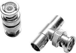
The Bayonet Navy Connector (BNC) is a small, cheap connector using a quick-connect half turn (the same connector found on 10base2 Ethernet). The BNC (shown in Figure 6-12) isn't well suited for 2.4GHz use, but it is mentioned here because, with the death of 10base2, the connectors are frequently sold for pennies per pound. Don't be tempted.
Figure 6-12. BNC: Bayonet Navy Connector (or Bayonet Neill Concelman, depending on who you ask)
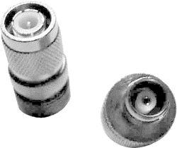
The TNC (see Figure 6-13) is a threaded version of the BNC. The fine threads help eliminate leakage at microwave frequencies. TNCs work well all the way through 12GHz and are often used with smaller (and higher loss) cable.
Figure 6-13. TNC (threaded BNC)
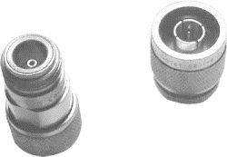
An N ("Navy" or "Neill") connector is a larger, threaded connector found on many commercial 2.4GHz antennas (see Figure 6-14). It is much larger than the TNC. It works very well on thicker cable (like LMR-400) and operates well up to 10GHz. The N is probably the most commonly encountered connector when dealing with 802.11b-compatible gear.
Figure 6-14. N connector
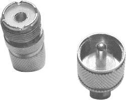
The so-called UHF connector looks like a coarse-thread version of the N (see Figure 6-15). It's not usable for 2.4GHz, but it is frequently confused with the N. According to the ARRL Microwave manual, it's a PL-259 (which mates with the SO-239 socket). It's not designed to work at microwave frequencies. You should avoid it.
Figure 6-15. The so-called "UHF" connector
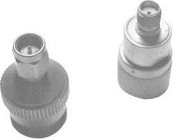
 The SMA connector (Figure 6-16) is a very popular, small, threaded connector that works great through 18GHz. Their small size precludes using them with large, low-loss cable.
 Figure 6-16. SMA: Sub-Miniature connector, variation A
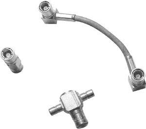
 The SMB (Figure 6-17) is a quick-connect version of the SMC.
 Figure 6-17. SMB: Sub-Miniature connector, variation B
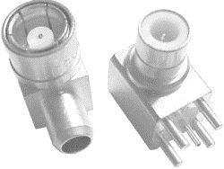
The SMC (see Figure 6-18) is a very small version of the SMA. It's good through 10GHz, but it accepts only very small (high-loss) cables. If only radio manufacturers had standardized on this as the external antenna connector of choice, there would be no call for custom pigtails.
Figure 6-18. SMC: Sub-Miniature connector, variation C
The APC-7 ( Figure 6-19) is a 7mm sexless connector, usable through 18GHz. It is a highgrade connector manufactured by Amphenol, and it is expensive, fairly rare, and very low loss.
Figure 6-19. APC-7: Amphenol Precision Connector
Remember that each connector in the system introduces some loss. Avoid adapters and unnecessary connectors whenever possible. Also, commercially built cables tend to be of higher quality than cables you terminate yourself (unless you're really good and have the right tools). Whenever possible, try to buy a pre-made cable with the proper connectors already attached, at the shortest length you can stand. 802.11b gear doesn't put out much power, and every little bit helps extend your range and reliability. It's very easy to make a bad cable, and bad cables can cause no end of trouble.
When matching cables to your equipment, you may encounter connectors of reverse gender (male and female swapped, with same threads), reverse threading (lefthand instead of righthand thread), or even reverse gender reverse threading (both). Make sure you know what you're getting before you order parts online!
On outdoor installations, proper lightning protection is vital. Gas tube lightning arrestors (see Figure 6-20) can provide a high degree of protection (both for your equipment and against fire) from lightning strikes to your antenna.
Figure 6-20. A gas tube lightning arrestor
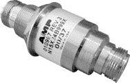
They cost anywhere from $30-100, and they can provide multistrike protection when properly installed. Be sure to read up on proper installation, use good quality grounding line, and, when in doubt, call in a professional. Most arrestors I've seen have female N connectors on either end, so be sure to factor that in when considering your hardware installation.
6.2.3 Calculating RangeHow far will your signal go? That's a very good question. It depends on all sorts of factors, including the power output and sensitivity of your card, the quality of your cable, connectors, and antenna, intervening clutter and noise, and even weather patterns (on long distance links). While it's impossible to take all of these variables precisely into account, you can make a good estimate before buying any hardware. Here's a simple way to build an estimate (frequently referred to as your link budget).
First, figure out how much loss the signal will incur in the space between the two sites. This is called the path loss. One common formula for estimating path loss at 2.4GHz is:L = 20 log(d) + 20 log(f) + 36.6
where L is the loss in dB, d is the distance in miles, and f is the frequency in megahertz.
Suppose you wanted to set up a five-mile link between two points, using channel 6 (2.437 GHz):
L = 20 log(5) + 20 log(2437) + 36.6
L = (20 x 0.69) + (20 x 3.38) + 36.6
L = 13.8 + 67.6 + 36.6
L = 118
At five miles, with no obstacles in between, you will lose 118 dB of signal between the two points. Our link must tolerate that much loss (plus a bit extra to account for weather and miscellaneous interference) or it will be unreliable.
Next, add up all of your gains (radios + antennas + amplifiers) and subtract your losses (cable length, connectors, lightning arrestors, and miscellaneous other losses). Let's assume you are using Orinoco Silver cards (15dBm), no amplifiers, with a 12dBi sector on one side, and a 15dBi yagi on the other. We'll assume you're using one meter of LMR-400 and a lightning arrestor on each side, allowing 0.25dB loss for each connector, and 1dB for each pigtail. Since all of the units are in dB, we can use simple addition and subtraction:
radio - pigtail - arrestor - connector - cable - connector + antenna
Site A: 15 - 1 - 1.25 - 0.25 - 0.22 - 0.25 + 12 = 24.03
Site B: 15 - 1 - 1.25 - 0.25 - 0.22 - 0.25 + 15 = 27.03
A + B = 51.06 total gain
51.06 - 118 = -66.94
This is the perceived signal level at each end of the link: -66.94dBm. But is it enough for communications?
Looking up the receiver sensitivity specs for the Orinoco Silver card (you have to look for it, but it is buried in the manual), we find the results shown in Table 6-2.
Table 6-2. Receiver sensitivity matrix for Orinoco Silver cards
11Mbps 5.5Mbps 2Mbps 1Mbps
-82 dBm -87 dBm -91 dBm -94 dBm
Because we are generating a signal of -66.94dBm, we have a "fudge factor" of 15.06dB (82 - 66.94 = 15.06). Theoretically, this will usually work at 11Mbps (in good weather) and should have no problem syncing at 5.5Mbps. The radios should automatically sense when the link becomes unreliable and resync at the fastest possible speed.
Typically, a margin of error of 20dB or so is safe enough to account for normal intervening weather patterns. Using more powerful radios (such as the Cisco 350, at 20dBm) or higher gain antennas would help shore up this connection to 11Mbps. Using higher gain cards (such as the Cisco or Teletronics cards) in conjunction with high gain dishes make it possible to extend your range well beyond 25 miles.
Online tools like Green Bay Professional Packet Radio's Wireless Network Link Analysis can give you a good ballpark estimate on what it will take to make your link possible; you just fill in a couple of blanks on a web form. Check out their excellent resources at http://www.qsl.net/n9zia/wireless/page09.html.