here you go now, the technical part, these are some of the basic skills you will require to make iot devices, little bit of engineering.
you will be designing circuits for your iot devices, therefore you need to understand at least basic electronic concepts.
good understanding of mathematics is also essential, since ebooks you are referring for electrical engineering will contain symbols and calculations
that's why i will recommend you go through video series rather than books, since you will be confused when symbols are used and you will have to remember what that symbol is called, in video series symbols are said out loud
learn physics, chemistry, maths, mechanical, maths
learning all these subjects help you in better understanding and the video series is cool and easy to understand, you can take 7 days free trial, and then again sign up with another email id and continue with 7 days free trial
i am no way related to them, but there tutorials have helped me a lot.
you can also learn on youtube, plenty of engineering tutorials available
knowledge of electronic engineering is essential
some basic understanding below
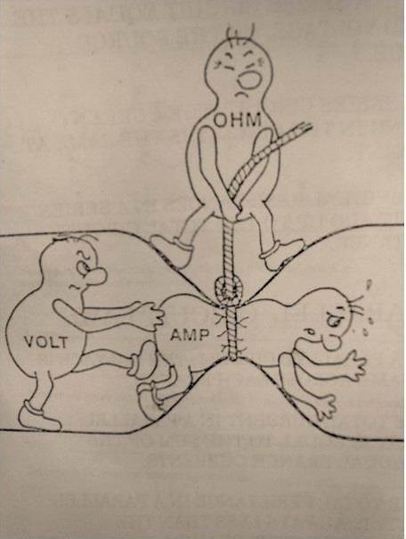
the above image best explains voltage current and resistor
voltage is the energy flowing the circuit, energy per unit charge and the current is the rate of the flow of the charge.
Current is the effect (voltage being the cause). Current cannot flow without Voltage.
every metal has some kind of resistance to the current flow, metal has some vibrating photons when the electrons try to move they get hit on photons and energy is released as a heat.
when the metal is cooled, photons are stable and electrons flow is smooth, some metals at specific point of temperature has zero resistance to the electric flow, they are called super conductor
in short you just need to understand, current resistance is higher when the metal is hot and very less or sometimes zero when the metal is cold.
you must have noticed considerable drop in motorbike and car pickup during hot summers
ohm's law is the most fundamental law of electrical engineering, it's everywhere in electronics world, learn more about ohm's law, in books it will be used as a symbol

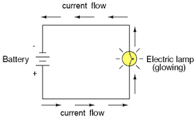
above image is basic circuit design, here the current flow is shown from positive to negative, but actually it is from negative to positive, conventional electronics use this way, but current flow is from negative to positive
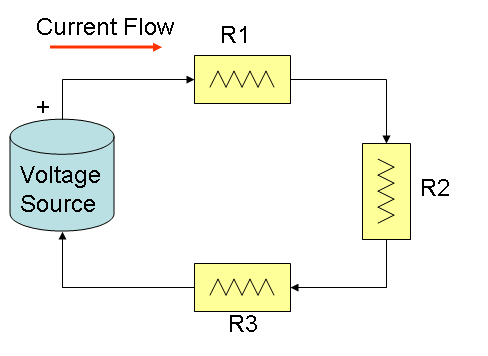
in the above image, the R1, R2, R3 are resistors, they slow down the current flow, when you design your basic circuit board, using breadboard you will be using resistors so that you don’t fry up your LED bulbs, when you are learning
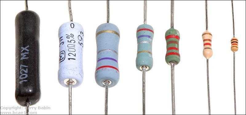
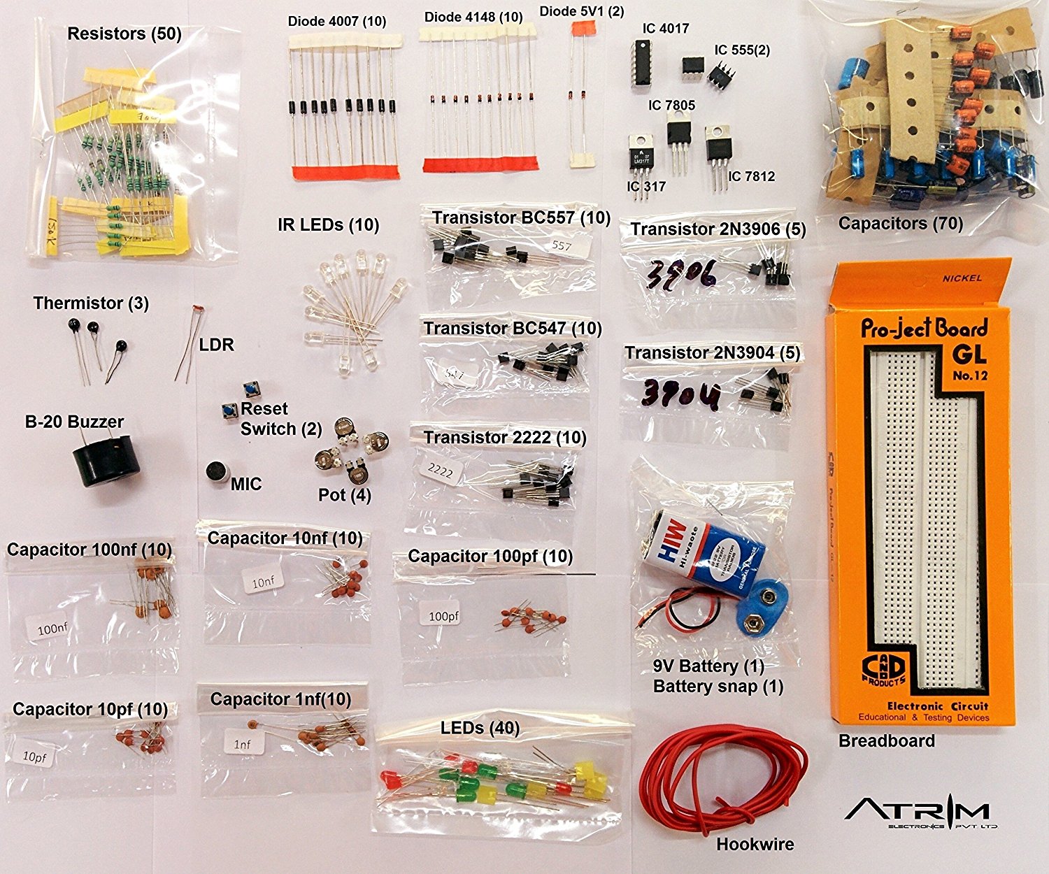
the above image is of resistors, they look like this
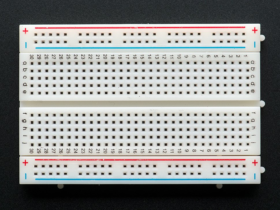
the above image is of breadboard, you will need to practise circuits
you will need this toolkit, if you wanna practise your electrical engineering
while learning you will be using breadboard, so that you can create circuits without soldering, and you can design and redesign your circuits
breadboards are best place to start. That is the real beauty of breadboards–they can house both the simplest circuit as well as very complex circuits.
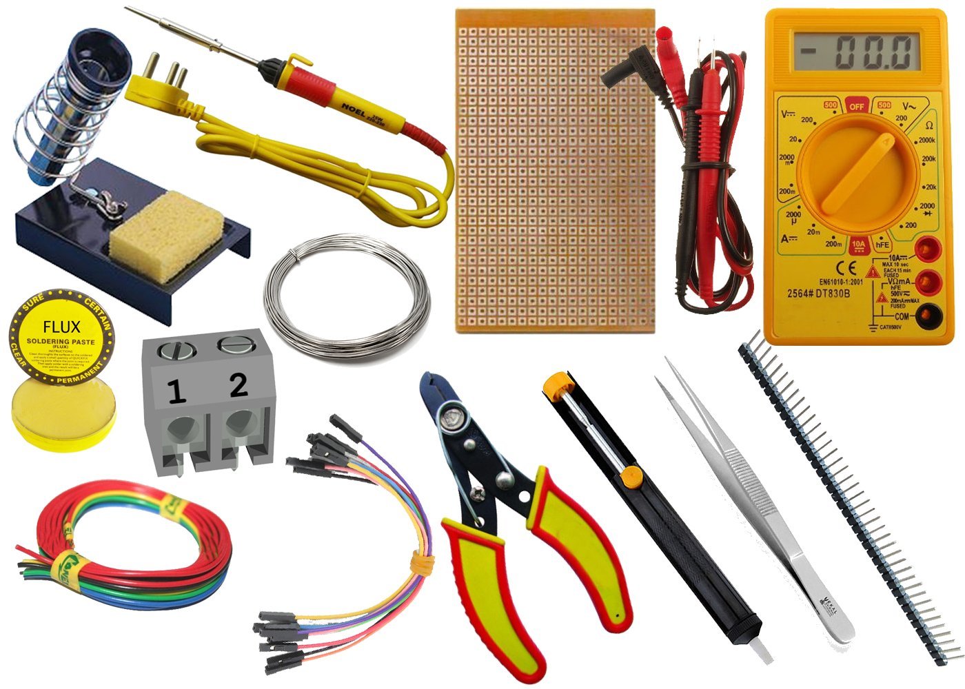
you will also need this toolkit
you can buy it from here
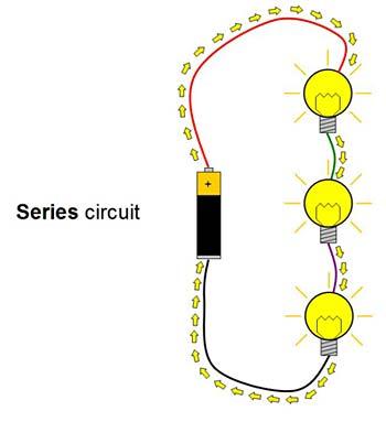
above image is the example of serial circuit, even if the one bulbs stops working entire circuit will fail, people from old school have seen series circuit, like in diwali if one bulb fails, entire decoration fails
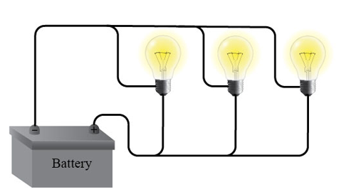
in this circuit even if one or two bulbs fail, circuit is not broken, so entire circuit doesn’t fail
Now that you know about electrical engineering, you must be ready for making your own iot device, lets start
you either will be using microcontroller or microprocessor for your iot device, they both are similar in nature with some differences and usefulness
Microcontrollers are designed to perform specific tasks. Specific means applications where the relationship of input and output is defined. Depending on the input, some processing needs to be done and output is delivered. For example, keyboards, mouse.
Microprocessor find applications where tasks are unspecific like developing software, games, websites, photo editing, creating documents etc. In such cases the relationship between input and output is not defined. They need high amount of resources like RAM, ROM, I/O ports etc.
The clock speed of the Microprocessor is quite high as compared to the microcontroller. Whereas the microcontrollers operate from a few MHz to 30 to 50 MHz, today’s microprocessor operate above 1GHz as they perform complex tasks.
microcontroller is lot cheaper than microprocessor
microcontroller cannot be used in place of microprocessor it won't be a good idea, as it will make the application quite costly. Microprocessor cannot be used stand alone. They need other peripherals like RAM, ROM, buffer, I/O ports etc and hence a system designed around a microprocessor is quite costly.