


Assistant Online - Maya/How Tos/Dynamics/Balloon
Alias|Wavefront / Assistant Online / Maya / How Tos / Dynamics / Balloon
HOW TO CREATE AN
by Bob Gundu
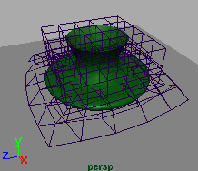
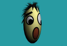
INFLATING BALLOON
MAYA Complete
Particle Dynamics
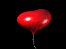
In this lesson, you will
learn how to use particle
dynamics and lattice
deformers to animate a
balloon being inflated.
This will be
accomplished by
converting a lattice into a
soft body and emitting it
from a particle emitter.
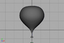
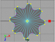
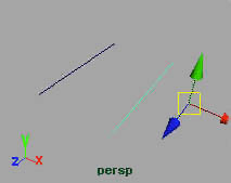
STEP ONE
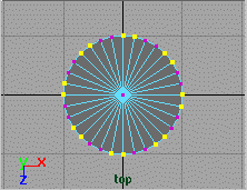
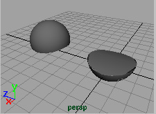
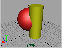
Create a profile curve for
the balloon off the Y-axis.
Revolve the curve to
create the surface.
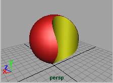
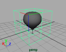
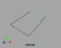
STEP TWO
With the balloon selected,
select Deform -> Create
Lattice -> Options. Set
the Divisions to the
following:
S = 3,
T = 3,
U = 3
Set Grouping to on. Press Create.
http://www.aw.sgi.com/assistant_online/entertain/maya/how_tos/dynamics/balloon/ (1 of 5) [3/7/2000 14:25:08]


Assistant Online - Maya/How Tos/Dynamics/Balloon
STEP THREE
You will now make the
lattice a soft body.
Select
●
ffd1Lattice.
Select
●
Bodies ->
Create Soft Body
-Options, and set
the following:
Hide Non-Soft Object to On
Make Non-Soft a Goal to On
Weight to .6
Press
●
Create.
Open the Attribute Editor for
●
ffd1LatticeParticleShape and
expand the Soft Body Attributes section.
Set Enforce Count from History to Off.
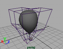
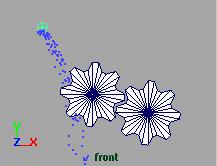
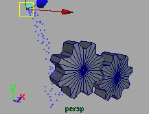
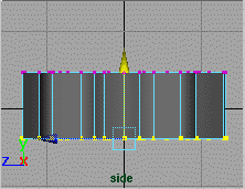
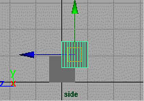
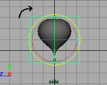
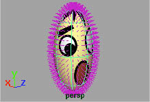
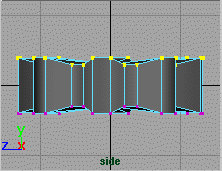
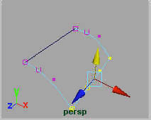
STEP FOUR
The particles are emitted
in a systematic order
corresponding to the
numbering of the lattice
points or CV's. The
current orientation of the
lattice will result in the
balloon being inflated
from left to right. You
would rather have it inflate from the bottom to top. It is for this
reason you will rotate the lattice 90° around the X-axis.
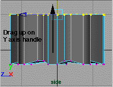
Select
●
ffd1Base, copyOfffd1Lattice, ffd1Base1, and
fd1Lattice.
Rotate
●
X to 90 degrees.
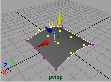
Ensure the balloon is fully enclosed within the lattice. Scale the
selected nodes if needed.
http://www.aw.sgi.com/assistant_online/entertain/maya/how_tos/dynamics/balloon/ (2 of 5) [3/7/2000 14:25:08]


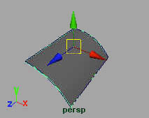
Assistant Online - Maya/How Tos/Dynamics/Balloon
STEP FIVE
You are now going to
create an emitter and
connect it to the soft
body.
Select
●
Particles ->
Create Emitter.
Move the emitter to
●
the base of the
balloon.
In the Outliner
●
delete the particle
shape node that is
created by default
with the emitter.
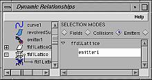
Open the
●
Dynamic
Relationships
editor and set
Modes to Emitters.
Select
●
ffd1LatticeParticle
and connect it to
emitter1.
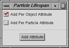
STEP SIX
Select the
●
ffd1LatticeParticle.
In the Attribute
●
Editor, add a Per
Object Lifespan
attribute.
Select the emitter
●
and set the Rate
to 0.
Set the
●
Playback
Range to 70 and
play the animation
until the balloon
disappears.
Select
●
Solvers ->
Initial State ->
Set For All
Dynamic.
http://www.aw.sgi.com/assistant_online/entertain/maya/how_tos/dynamics/balloon/ (3 of 5) [3/7/2000 14:25:08]


Assistant Online - Maya/How Tos/Dynamics/Balloon
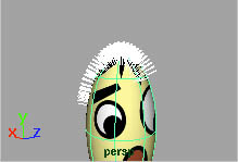
STEP SEVEN
Set the emitter
●
Rate
to 100 and the
ffd1LatticeParticle
Lifespan to 5.
Go back to frame
●
1
and playback the
animation.
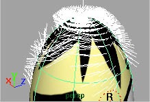
CONCLUSION
You now have a balloon being inflated from a point. The main
concept here is that when an object is converted to a soft
body, the CV's or lattice points are converted to particles, and
therefore are able to be emitted from a particle emitter.
Tips:
Increasing the density of the lattice requires a higher
●
emitter rate.
Decreasing the Goal Weight will require a smaller emitter
●
rate
You can emit the same object from more than one
●
emitter.
You can attach several deformers to the same object.
●
Quick Clips:
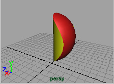
An example of using two lattices on the same object. Simply
select half the CV's on the balloon and apply the lattice. Do the
same for the other half and rotate direction of lattice.
Two Emitters [~158k]
This example uses two emitters to emit geometry. One is
placed at the bottom and the other in the center of the balloon.
Experiment with having different emitter rates for each emitter.
Emitting Geometry [~158k]
This example is shows geometry instead of a lattice being
emitted. Experiment with changing the surface direction of the
object for different effects.
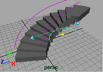
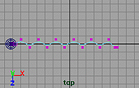
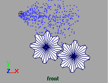
This is to demonstrate the order of emission of the lattice
points when using default position of the lattice. For clarity, the
lattice is much denser than in the tutorial. In the tutorial the
lattice was rotated 90 degrees to emit from the bottom up.
This is the final project file you may download for comparison.
http://www.aw.sgi.com/assistant_online/entertain/maya/how_tos/dynamics/balloon/ (4 of 5) [3/7/2000 14:25:08]


Assistant Online - Maya/How Tos/Dynamics/Balloon
Use of this file confirms your agreement to the Terms and Conditions
set out on the Terms and Conditions page.
http://www.aw.sgi.com/assistant_online/entertain/maya/how_tos/dynamics/balloon/ (5 of 5) [3/7/2000 14:25:08]


Assistant Online - Maya/How Tos/Dynamics/Chain Link
Alias|Wavefront / Assistant Online / Maya / How Tos / Dynamics / Chain Link
HOW TO ANIMATE A CHAIN LINK
By Robert Magee
MAYA Complete
Rigid Body Dynamics
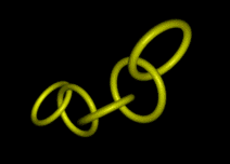
In this lesson, you will
learn how to use Rigid
Dynamics to animate a
chain of links. To
animate the chain link,
you will use a nail
constrain and a gravity
field.
STEP ONE
Create a polygonal
Torus primitive. Edit the
polyTorus input node in
the channel box. Be
sure to set the
Subdivisions so that the
Subdivisions in the X
direction are about 40
and in the Y direction
15. Scale XYZ to 2, and
the Section Radius to
0.1.
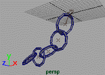
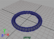
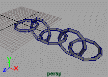
STEP TWO
Make five duplicates of
the link. Move and
Rotate the links to form
a chain. Move all of the
links so that the edge of
the first link is at the
origin.
http://www.aw.sgi.com/assistant_online/entertain/maya/how_tos/dynamics/chain_link/ (1 of 2) [3/7/2000 14:25:38]


Assistant Online - Maya/How Tos/Dynamics/Chain Link
STEP THREE
Select all of the chains
then select Fields ->
Create Gravity. This
turns all the links into
rigid bodies and
connects them to a
gravity field. Next select
the first link then select
Bodies -> Create
Constraint. This places
a nail dynamics
constraint at the origin.
STEP FOUR
Set your playback
range to 300 frames
then play back the
simulation.
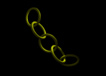
Play Movie [~704 Kb]
CONCLUSION
This was a very simple example of how to use rigid body
dynamics. If the objects had been more complex, these high
resolution links could be parented to new low resolutions
links. These low resolution models would be used in the
dynamic simulation to increase interactive performance.
Use of this file confirms your agreement to the Terms and Conditions
set out on the Terms and Conditions page.
http://www.aw.sgi.com/assistant_online/entertain/maya/how_tos/dynamics/chain_link/ (2 of 2) [3/7/2000 14:25:38]


Assistant Online - Maya/How Tos/Dynamics/Ring of Fire
Alias|Wavefront / Assistant Online / Maya / How Tos / Dynamics / Ring of Fire
HOW TO CREATE A RING OF FIRE
by Paul Anand
MAYA Complete
Particles
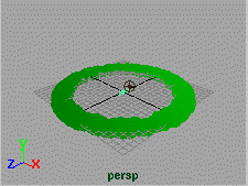
This lesson teaches
you how to create a
ring of fire using a
particle runtime
expression. This
expression, combined
with some keyframes,
will help define the
emission of the
Play movie [~483kb]
particles into a ring
shape.
At the end of the lesson, you will apply a particle cloud shading
group to define the look of the ring.
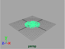
STEP ONE
Select Particles ->
Create Emitter. In either
the Attribute editor or the
Channel box, change
the Emitter Type to
Omni.
Playback the simulation
then stop after a few
frames. Select the particles.
Select Window -> Attribute Editor. In the Per Particle (Array) Attributes section, click on the velocity field with your right mouse button. Choose RunTime Expression from the pop-up
menu.
Enter the following in the expression box:
/* Put Velocity before manipulation in $getVel */
vector $getVel = velocity;
/* Zero out the Y velocity and put the resulting Vector in $newVel */
vector $newVel = <<$getVel.x,0,$getVel.z>>;
http://www.aw.sgi.com/assistant_online/entertain/maya/how_tos/dynamics/fireRing/ (1 of 3) [3/7/2000 14:25:45]

Assistant Online - Maya/How Tos/Dynamics/Ring of Fire
/* Get the magnitude of the original velocity */
float $initMag = mag($getVel);
/* Get the magnitude of the new velocity */
float $aftMag = mag($newVel);
/* Set the new velocity to have same magnitude as original */
$newVel = ($newVel / $aftMag) * $initMag;
/* Apply our new velocity to the particles */
velocity = $newVel;
Click Create.
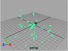
Playback to see the results. The particles are emitted along the
X and Z axes but not along Y.
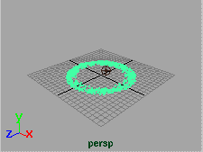
STEP TWO
You will now set keys on
the rate of emission to
form the inner and outer
surface of the ring.
Go to frame 1.
Select the Emitter. In the
Channel box, set the
Speed to 2 and the Rate
to 1000. Now select the Rate attribute then click with your right mouse button and select Key Selected.
Go to frame 30. Set the Rate to 100. Set another key.
Go to frame 31. Set the Rate to 0. Set another key.
Playback the results. Now the emission is defined by the keys
and the particles form a ring.
STEP THREE
Now that you have the
motion, you can set the
render type. You will use
a pre-built particle cloud
shading network to
create the effect.
Shift-click to download
current project's
Textures directory, or use the 'Show Me' button on the
Select the particles. In the Attribute editor, go to the Render
Attributes section and change the Render Type to Cloud.
Select File -> Import and load the file called FireCloud.ma.
http://www.aw.sgi.com/assistant_online/entertain/maya/how_tos/dynamics/fireRing/ (2 of 3) [3/7/2000 14:25:45]


Assistant Online - Maya/How Tos/Dynamics/Ring of Fire
Open the Hypershade.
With the particles selected, select FireCloud.ma in the
Hypershade with the Right Mouse Button select Assign
Material to Selection.
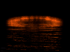
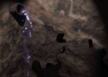
STEP FOUR
Add a light to the scene
to illuminate the
particles. You can now
add other objects to the
scene such as the water
surface shown here.
Use the batch render to
render the scene with
Animation set to On.
CONCLUSION
Particle runtime expressions let you control various particle
attributes to help you control their emission.
Your use of this file confirms your agreement to the
Terms and Conditions set out in the Terms and Conditions page.
http://www.aw.sgi.com/assistant_online/entertain/maya/how_tos/dynamics/fireRing/ (3 of 3) [3/7/2000 14:25:45]


Assistant Online - Maya/How Tos/Dynamics/Fireball
Alias|Wavefront / Assistant Online / Maya / How Tos / Dynamics / Fireball
HOW TO CREATE AN EXPLODING FIREBALL by Chris Ford
MAYA Complete
Particles
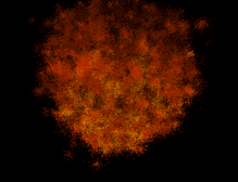
This lesson teaches you
how to create the fireball
from an explosion. The
lesson also talks about
techniques for the
Hardware and Software
rendering of fire effects.
You will start by
generating all the
particles used in the
explosion in the first 30
frames of the animation. These particles will be exploded at
high speed into the surrounding atmosphere, which you will
simulate using a Drag field. A Turbulence field is used to
create eddies and swirls in the expanding fireball, and a
reversed Gravity field is used to give the explosion particles
buoyancy.
To complete this lesson, you should be familiar with the
Hardware Render buffer, and basic Software particle rendering.
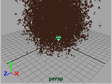
STEP ONE
Select Particles ->
Create Emitter. In either
the Attribute editor or the
Channel box, change the
Emitter Type to Omni
and the Speed to 25.
Playback the simulation
then stop after a few
frames. Select the particles. In the Attribute editor, change the
Render Type to MultiStreak.
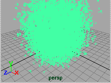
Again playback the scene. You now have a few particles
emitting at a constant rate. You want the particles to explode
http://www.aw.sgi.com/assistant_online/entertain/maya/how_tos/dynamics/fireball/ (1 of 6) [3/7/2000 14:25:57]
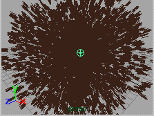

Assistant Online - Maya/How Tos/Dynamics/Fireball
then fade. You will need to animate the emitter's Rate attribute.
STEP TWO
Make your playback
range go from frame 1 to
frame 50
Select the emiitter. Go to
frame 1. Set the Rate to
0 and select Key
selected from the
Channel box menu. Go
to frame 30 and set a second key.
Go to frame 3. Set the Rate to a high value such as 10000 and select Key selected from the Channel box menu.
Playback the scene. The particles are now exploding but they
are not reacting in a natural manner. You now need to add
some fields to give the explosion a more complex motion.
STEP THREE
Select the particles then
select Fields -> Create
Turbulence. This will
shake up the particles as
they emit.
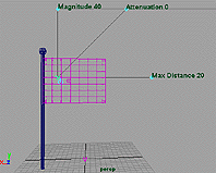
Set the field's
Magnitude to 100,
Frequency to 100, and
Attenuation to 0.
Again, select the particles then select Fields -> Create Drag.
Set the drag's Magnitude to 5 and Use Max Distance to Off.
The drag will be used to simulate the reaction of the explosion
to the atmosphere.
Again, select the particles then select Fields -> Create Gravity.
Set the Magnitude to 20 and the Direction to 0,1,0. This field is aiming away from the ground so that it will pull the particles
up in a gaseous manner.
Playback the scene. The motion of the particles is more
interesting but they need some color. Over the next few steps,
you will apply lifespan, opacity, and color attributes to the
explosion particles, and take a look at them animating with
Hardware shading turned on.
Tip: By making sure that the particles are selected when you create a field, they will be automatically connected to the field.
Tip: When creating Fields, always assume that the Attenuation attribute should be 0.
http://www.aw.sgi.com/assistant_online/entertain/maya/how_tos/dynamics/fireball/ (2 of 6) [3/7/2000 14:25:57]


Assistant Online - Maya/How Tos/Dynamics/Fireball
STEP FOUR
Select particles and
open the Attribute Editor.
Go to the Add Dynamic
Attributes tab, and click
on Lifespan, Opacity
and Color.
Choose Add PerParticle
attributes for all of the
options.
Click with your RMB on the lifespanPP field, and select
Runtime Expression... . This will open the expression editor
where you will the following expression:
particleShape1.lifespanPP = rand(.5,4);
This expression makes the particles disappear or "die" at
different rates by randomly assigning each particle a lifespan
somewhere between .5 (min. value) and 4 (max. value).
Playback the simulation. If the particles die too soon, click with
your RMB on the lifespanPP field and select Runtime
Expression... . Adjust the expression's min. and max. values to
set the desired range for how long the particles will "live" before they "die". Click the Edit button, then click the Close button and playback the results.
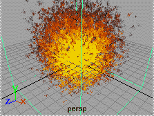
STEP FIVE
Click with your RMB on
the rgbPP field, and
select Create Ramp.
Edit Ramp with three
colors: a flame yellow,
flame Red, and Black.
Click with your RMB on
the OpacityPP field, and
select Create Ramp.
Press 6 on the keyboard to hardware shade the particles, and
Playback. Now you see the particles start out yellow then turn
red and black. You can edit the parts of the ramp to control
when the different colors kick in.
If you are happy with the motion and the look of the particles,
you can now choose to complete the rendering as a hardware
rendering or use software rendering. Both options are outlined
below:
http://www.aw.sgi.com/assistant_online/entertain/maya/how_tos/dynamics/fireball/ (3 of 6) [3/7/2000 14:25:57]

Assistant Online - Maya/How Tos/Dynamics/Fireball
Hardware render
The hardware render
buffer can be used to
render out your explosion
using the following steps:
In the Attribute
●
Editor, in the
Render Attributes
section, set the
Depth Sort to On.
●
Click on Add
Attributes for:
Current Render
Type. This adds
new attributes to
the particle.
Increase the
●
Line
Width to 2, Multi
Count to 25, and
Multi Radius to
0.75.
Select Window -> Rendering Editors -> Hardware Render Buffer to test a sequence. Use a Multi Pass Rendering setting of 5 to get a softer effect.
Use the Hardware render Buffer flipbooks to preview the
dynamics of the scene. You can now composite the explosion
into other scenes using a compositing package like Maya
Composer or Maya Fusion.
Tip: Do not use any Color Accumulation, since this attribute tends to burn out the center of an explosion effect.
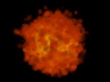
Software render
You can generate very
realistic rendered
fireballs with software
particle rendering using
the Particle Cloud
Shader. The following
items tell you how to
create an explosion
shader.
Select the
●
explosion particles
and, in the Attribute
Editor, change
Render Type to
Cloud (s/w). Turn
Depth Sort to On.
http://www.aw.sgi.com/assistant_online/entertain/maya/how_tos/dynamics/fireball/ (4 of 6) [3/7/2000 14:25:57]

Assistant Online - Maya/How Tos/Dynamics/Fireball
Go to the
●
Add
Dynamic
Attributes section,
and click the
General Tab.
Open the Particle
tab and select and
add radiusPP from
the list of Particle
attributes.
Click with your
●
RMB on radiusPP
and create this
Creation
Expression:
radiusPP = rand(0.1,
0.75);
This will randomise within the specified random number limits,
the radius of each particle cloud shader on a per-particle basis.
If you do not do this, then the fireball will render in a very
regular manner.
Select Window -> Hypershade. Select Create -> Create Render Node... , and under Volumetric Materials, choose a
Particle Cloud material. You will notice that the Color ramps
you made for rgbPP are already in the Hypershade.
Double-click on the new Particle Cloud material node. Drag
and drop the rgb color ramp onto the Map... button opposite
Life Color .
Connected to the ramp in the Hypershade Utilities section, is
the Particle Age Mapper. You can increase this to speed up
the rate with which the particles change color as they age.
Map a 3D texture SolidFractal into the transparency of the
Particle Cloud shader. Select the explosion particles in the
modeling view and assign the particle shader.
Add a light to illuminate the fireball.
Select Render -> Render into New Window.
CONCLUSION
You now have two particle effects to help you explore the
differences between hardware and software rendered
particles.
Use of this file confirms your agreement to the Terms and Conditions
set out on the Terms and Conditions page.
http://www.aw.sgi.com/assistant_online/entertain/maya/how_tos/dynamics/fireball/ (5 of 6) [3/7/2000 14:25:57]


Assistant Online - Maya/How Tos/Dynamics/Fireball
http://www.aw.sgi.com/assistant_online/entertain/maya/how_tos/dynamics/fireball/ (6 of 6) [3/7/2000 14:25:57]


Assistant Online - Maya/How Tos/Dynamics/Flag
Alias|Wavefront / Assistant Online / Maya / How Tos / Dynamics / Flag
HOW TO CREATE A FLAG USING SOFT
by Steve Christov
BODIES
Maya Complete
Soft Body particles
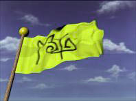
In this lesson you will learn
how to create a flag by
turning a NURBS plane into
a soft body.
You will then use the Artisan
tools to paint Goal weights to
on the soft body particles to
allow the cloth to react to
Play Movie[~480kb]
forces such as wind and turbulence.
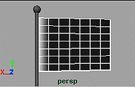
STEP ONE
Create a simple sphere and
a cylinder and scale these
out to become your flagpole.
In the menu bar select
Create-NURBS Primitives >
Plane-Options. Change the
U and V patches to 12.
Scale the plane to get a shape of a rectangle. Set Rotate X to 90 and Move it to resemble a flag hanging off a flag pole.
Press F8 to go into Component Mode. In your top view select
every other CV and move them up slightly. Now select the other
CVs and move them down slightly to create a ripple surface.
Press F8 to return to Object Mode.
http://www.aw.sgi.com/assistant_online/entertain/maya/how_tos/dynamics/flag/ (1 of 4) [3/7/2000 14:26:12]


Assistant Online - Maya/How Tos/Dynamics/Flag
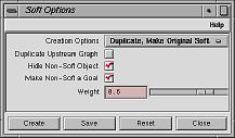
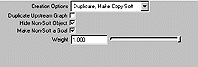
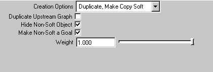
STEP TWO
You will now convert your
Plane to a soft body.
Select the surface and in
your dynamics menu click on
Click here to view larger image
Bodies > Create Soft
Body-Options.
In the option box set the following:
Creation Options
●
to Duplicate,
Make Copy Soft
●
to On
Hide Non-Soft Object
●
to On
Make Non-Soft a Goal
●
to On.
Goal weight
●
to 1.0.
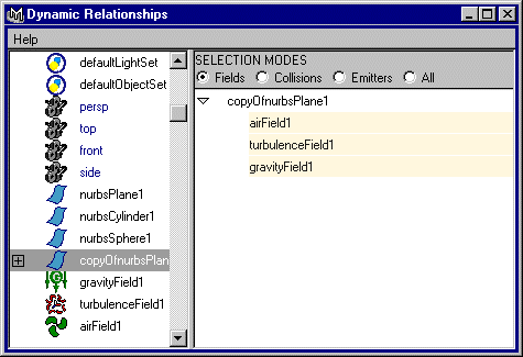
STEP THREE
With nothing selected, select
Dynamics > Fields >
Gravity , Turbulence and
Air
Select and Move the Air
Field to an area behind the
flag.
Click here to view larger image
Select and Move the
Turbulence Field up to the middle of the flag.
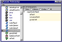
Select Window > Relationship Editor > Dynamic
Relationships. Scroll down to select copyOfnurbsPlane,
highlight the fields in the right hand window.
With the copyOfnurbsPlane still selected, Click on the Bodies >
Create Springs > Options.
Set the Max distance to 1.0, and set the Wire Walk Length to 3. Click on Create.
Playback your scene. While these forces are connected and
acting on the softbody, you are not getting any results. This is
because of the fact that when you created the soft body you
assigned a goal weight of 1, which results in the soft body
always achieving its goal of maintaining it's original shape. You
will need to adjust goal weights of the individual particles so
that the soft body will not always achieve its goal. For this you
will use the Artisan brushes to tweak the goal weights of the
soft body to get a realistic flag.
http://www.aw.sgi.com/assistant_online/entertain/maya/how_tos/dynamics/flag/ (2 of 4) [3/7/2000 14:26:12]


Assistant Online - Maya/How Tos/Dynamics/Flag
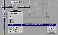
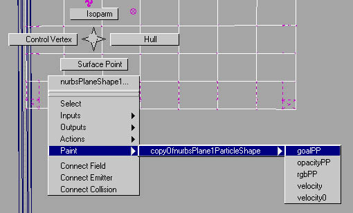
STEP FOUR
With your mouse over the
surface of the flag click with
your right mouse button, and
scroll down to Paint >
copyOfnurbsPlaneParticle
Shape > goalPP. Your
surface should turn white
Click here to view larger image
and your cursor should
become an Artisan brush.
Note: Make sure you have shading turned on by pressing 5 on
the keyboard.
STEP FIVE
Select the tool settings for
the brush, by double
clicking on its icon in the
tool bar shelf.
Click on the Display tab
and click to disable lighting.
Click on the Attr. Paint tab to bring up the brush attributes. Set
the value to 0.1.
Paint over all of the CVs except for the area near the pole. The
surface should give feedback on the changes you are making
to the goalweights by turning darker.
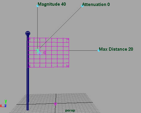
STEP SIX
Select the Air Field and show
the manipulator by pressing
the t key on your keyboard .
Using the blue circle beside
the icon, scale out the one
marked Magnitude to about
60.
Press on the blue circle and
change the direction of the
Click here to view larger image
air flow towards the flag. In
your channel box set Max Distance to Off, and Set
Attenuation to 0. This will ensure that the force does not
diminish with an increase in distance from the actual position of
the field.
Select the Turbulence field, and set the following.
● Magnitude to around 100
Attenuation
●
to 0.
http://www.aw.sgi.com/assistant_online/entertain/maya/how_tos/dynamics/flag/ (3 of 4) [3/7/2000 14:26:12]


Assistant Online - Maya/How Tos/Dynamics/Flag
Playback the animation.
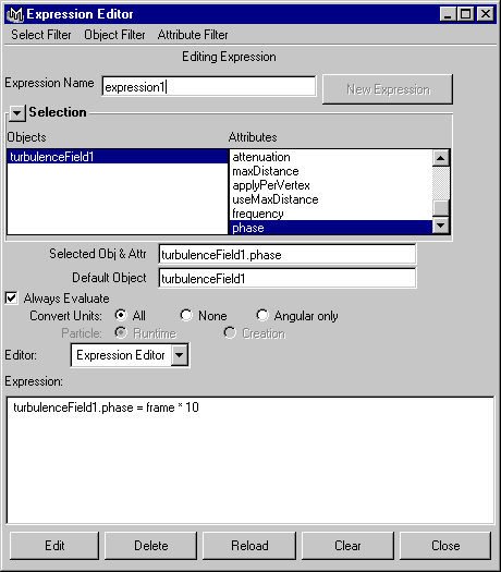
STEP SEVEN
If you playback the animation
at this point you will see that
the "shape" of the turbulence
seems to cycle over and
over and as a result you
don't quite get random
ripples. You can fix this by
animating the Phase
attribute over time.
Select the Phase attribute
and with your right mouse
button select expressions
from the pop-up menu.
Click here to view larger image
In the expression editor enter:
phase = frame * 10.
When you playback the animation at this point you will see that
the flag is now fluttering in the wind. Go to a frame where the
forces have evened out and in the menu go to Solvers > Initial
State > Set for all dynamic. You now avoid the first couple
frames where the forces need to start up.
CONCLUSION
This animation is the result of converting a simple plane into
a soft body which is then animated using forces such as wind
and turbulence. By adjusting the goal weights and tweaking
the dynamic forces you are able to create a realistic looking
flag. In the final animation the wind direction and magnitude
have been animated.
Download a finished scene file:
flag.ma[~144kb]
Use of this file confirms your agreement to the Terms and Conditions
set out on the Terms and Conditions page.
http://www.aw.sgi.com/assistant_online/entertain/maya/how_tos/dynamics/flag/ (4 of 4) [3/7/2000 14:26:12]
http://www.aw.sgi.com/assistant_online/entertain/maya/how_tos/dynamics/flag/img/flag02_big.gif http://www.aw.sgi.com/assistant_online/entertain/maya/how_tos/dynamics/flag/img/flag02_big.gif [3/7/2000 14:26:15]
http://www.aw.sgi.com/assistant_online/entertain/maya/how_tos/dynamics/flag/img/flag03_big.gif http://www.aw.sgi.com/assistant_online/entertain/maya/how_tos/dynamics/flag/img/flag03_big.gif [3/7/2000 14:26:18]
http://www.aw.sgi.com/assistant_online/entertain/maya/how_tos/dynamics/flag/img/flag04_big.jpg http://www.aw.sgi.com/assistant_online/entertain/maya/how_tos/dynamics/flag/img/flag04_big.jpg [3/7/2000 14:26:21]
http://www.aw.sgi.com/assistant_online/entertain/maya/how_tos/dynamics/flag/img/flag05_big.jpg http://www.aw.sgi.com/assistant_online/entertain/maya/how_tos/dynamics/flag/img/flag05_big.jpg [3/7/2000 14:26:25]
http://www.aw.sgi.com/assistant_online/entertain/maya/how_tos/dynamics/flag/img/flag06_big.gif http://www.aw.sgi.com/assistant_online/entertain/maya/how_tos/dynamics/flag/img/flag06_big.gif [3/7/2000 14:26:29]


Assistant Online - Maya/How Tos/Dynamics/Footprints
Alias|Wavefront / Assistant Online / Maya / How Tos / Dynamics / Footprints
HOW TO CREATE FOOTPRINTS
Alias|Wavefront
MAYA Complete
Particle Dynamics
In this lesson, you will
learn how to make
footprints in a wet mud
surface. It is a good
example of the
integration of character
animation and
dynamics working
together. There are at
least two ways to
approach this problem.
One method is to make
the boots rigid bodies,
and use rigid body/particle collision to make impressions in the
mud. The problem with this method is that rigid bodies cannot
bend as the sole of a boot does when walking. The second
method involves using fields attached to the boots to displace
mud made out of a softbody mesh. This lesson will use the
later method.
STEP ONE
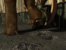
Open the scene file footprints.ma.
This scene file contains a pair of animated boots walking on a
flat mud surface. If you playback the scene, the mud is not
interacting with the boots. You will begin by turning the mud
surface into a soft body. Before beginning, set your view to
persp/outliner.
Select the
●
mud surface.
Select
●
Bodies -> Create Soft Body - Option, and set
the following:
Creation Options
❍
to Make Soft
Press
❍
Create.
Select
❍
mudParticles in the Outliner .
In the Channel Box, set the
❍
Conserve to 0.
http://www.aw.sgi.com/assistant_online/entertain/maya/how_tos/dynamics/footprints/ (1 of 4) [3/7/2000 14:27:05]


Assistant Online - Maya/How Tos/Dynamics/Footprints
STEP TWO
There still is no deformation in the mud because there are no
fields effecting it. You will be adding air fields to the sole and
the heel of each boot to achieve this effect.
In the Outliner, for the left boot, select
●
bootLsole, and
heelL.
Select
●
Fields -> Add Air - Options, and set the following:
Magnitude
■
to 100
Attenuation
■
to .5
Max Distance
■
to 0.2
Direction
■
to 0,-1,0
Press
■
Add.
Repeat this process for the right boot.
■
In the outliner you will notice that the boot pieces have air fields
parented to them.
STEP THREE
You will now use the
Dynamics Relationship
Editor to connect the mud
to the fields.
Select
●
Window ->
Relationship
Editors -> Dynamic
Relationships...
In the left column
●
select mud.
In the right column
●
select all of the
fields.
The fields are now connected. Playback the scene to see the
effect.
Note: Must you have the animation Playback Speed
preference set to Free.
http://www.aw.sgi.com/assistant_online/entertain/maya/how_tos/dynamics/footprints/ (2 of 4) [3/7/2000 14:27:05]

Assistant Online - Maya/How Tos/Dynamics/Footprints
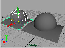
STEP FOUR
The movement of the mud
can look more realistic by
having the mud bulge
upward in front of the
boots.
This can be achieved by
parenting another field to
the boot that is pointing in
the upward direction. You
will also be creating an
expression on the
Magnitude attribute of the field to control for when the field is
active. In other words, the expression will limit the magnitude of
the field to operate only when the boot is at ground level and
have no influence when the boot rises above the ground.
Go back to frame
●
1.
Select
●
Fields -> Create Air - Options, press Reset, and set the following:
❍ Air Name to pushUpAirL
Attenuation
❍
to 0.5
Direction
❍
to 0,1,0
Speed
❍
to 1.0
Max Distance
❍
to 1.0
Press
●
Create.
Position
●
pushUpAirL just under the left toe of the boot .
In the Outliner,
●
MMB-drag pushUpAirL on top of bootL.
The airField pushUpAirL is now parented to bootL.
● Repeat the steps for the right boot and name the new
airField pushUpAirR.
Open the
●
Dynamic Relationships... editor and connect
both the pushUpAir fields to the mud surface .
STEP FIVE
You will now be adding the expression to the Magnitude
attribute of the pushUpAir airFields.
Select
●
pushUpAirL.
In the Channel Box, highlight the
●
Magnitude attribute.
With the
●
RMB over the Magnitude field, select
Expressions... from the pop-up menu.
Enter the following expression:
●
if (bootL.translateY > -3.0) {
pushUpAirL.magnitude = 0;
}
http://www.aw.sgi.com/assistant_online/entertain/maya/how_tos/dynamics/footprints/ (3 of 4) [3/7/2000 14:27:05]


Assistant Online - Maya/How Tos/Dynamics/Footprints
else {
pushUpAirL.magnitude = 50;
}
Press
●
Create.
Repeat these steps for
●
pushUpAirR.
Playback the scene
●
.
Depending on your placements of pushUpAir fields , the
bootL.translateY value in the expression may have to be adjusted
accordingly.
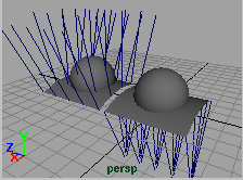
CONCLUSION
You now have
footprints that are
created using
softbodies and fields.
There are a couple of
things to note about this
workflow.
You may have noticed
that when you turned
the mud into a softbody,
Play Movie [~521K]
you did not create a goal for it. This is because the mud is not
returning to its original shape. It is also important to note that
the sole and the heel surfaces were rebuilt with even
parameterization to get an even distribution of the air field.
Your use of this file confirms your agreement to the
Terms and Conditions set out in the Terms and Conditions page.
http://www.aw.sgi.com/assistant_online/entertain/maya/how_tos/dynamics/footprints/ (4 of 4) [3/7/2000 14:27:05]


Assistant Online - Maya/How Tos/Dynamics/Melting Object
Alias|Wavefront / Assistant Online / Maya / How Tos / Dynamics / Melting Object
HOW TO ANIMATE A
by Bob Gundu
MELTING OBJECT
Updated! [09.28.99]
MAYA Complete
Particle Dynamics
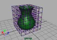
In this lesson, you will
learn how to use particle
dynamics and lattice
deformers to animate a
melting vase.
This will be accomplished
by converting a lattice
into a soft body and
adding collisions to the table surface. Other attributes will be
added to lattice for further control.
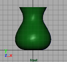
STEP ONE
Create a profile curve for
the vase off the Y-axis.
Revolve the curve to
create the surface.
http://www.aw.sgi.com/assistant_online/entertain/maya/how_tos/dynamics/melt/ (1 of 4) [3/7/2000 14:28:43]


Assistant Online - Maya/How Tos/Dynamics/Melting Object
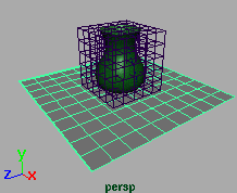
STEP TWO
With the vase selected,
select Deform -> Create
Lattice -> Options. Set
the Divisions to the
following:
S = 6,
T = 6,
U = 6
Press Create.
STEP THREE
You will now make the lattice a soft body.
Select ffd1Lattice. Select Bodies -> Create Soft Body
-options.
Reset all the settings.
Press Create.
STEP FOUR
Create a NURBS plane
underneath the vase.
Scale up the plane and
increase the subdivisions
to U 10, V 10.
Move the plane slightly
below the lattice soft body.
This is to make sure the
lattice deformer is not
penetrating through the plane surface before simulation.
STEP FIVE
You are now going to add a gravity field to the soft object and
particle collisions to the plane surface.
Select ffd1Lattice. Select Fields > Create Gravity. To add collisions, select ffd1Lattice then the plane surface. Select Particles -> Make Collide.
http://www.aw.sgi.com/assistant_online/entertain/maya/how_tos/dynamics/melt/ (2 of 4) [3/7/2000 14:28:43]


Assistant Online - Maya/How Tos/Dynamics/Melting Object
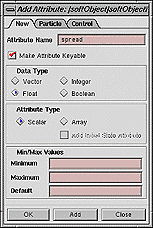
STEP SIX
You will notice an obvious problem
when you playback the animation
bouncing up and down and not
spreading outward. This can be
corrected with a simple expression
controlled by adding two attributes to
the ffd1LatticeParticleShape node.
In the Outliner, have Display >
Shape turned on. Select
ffd1LatticeParticleShape. Select
Modify -> Add Attribute... and set
the following:
● Attribute Name to spread;
Data Type
●
to Float;
Attribute Type
●
to Scalar
Press Add and repeat with another attribute:
Attribute Name to thickness
Press OK.
STEP SEVEN
With the new attributes on
the soft body, you will
now create an expression
to spread out the bottom
of the vase as it melts.
Select
ffd1LatticeParticleShape.
Open Window ->
Expression Editor.
Enter the following in the expression box:
vector $melt = ffd1LatticeParticleShape.worldPosition;
float $spread = ffd1LatticeParticleShape.spread;
float $thickness = ffd1LatticeParticleShape.thickness;
if ($melt.y < $thickness) ffd1LatticeParticleShape.velocity = unit
(ffd1LatticeParticleShape.worldPosition - <<0,0,0>>) * $spread; Press Create.
http://www.aw.sgi.com/assistant_online/entertain/maya/how_tos/dynamics/melt/ (3 of 4) [3/7/2000 14:28:43]


Assistant Online - Maya/How Tos/Dynamics/Melting Object
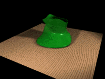
STEP EIGHT
It is now easy to control
the quality of the melt
with the spread and
thickness attribute.
Select the
ffd1LatticeParticle. In the
channel box, change the
spread to .4, and the
thickness to 1.
Playback the animation.
CONCLUSION
You now have a vase melting on a surface. Keep in mind
that you have several parameters that can be animated to
add more life:
to slow down the melting, decrease the
●
gravity
magnitude;
try experimenting with the
●
spread and thickness
attributes;
or even add a turbulence field to add more randomness to
the effect.
Use of this file confirms your agreement to the Terms and Conditions
set out on the Terms and Conditions page.
http://www.aw.sgi.com/assistant_online/entertain/maya/how_tos/dynamics/melt/ (4 of 4) [3/7/2000 14:28:43]


Assistant Online - Maya/How Tos/Dynamics/Particle Gears
Alias|Wavefront / Assistant Online / Maya / How Tos / Dynamics / Particle Gears
HOW TO USE PARTICLES
by Nancy Hosken
TO DRIVE RIGID BODIES
MAYA Complete
Particle Dynamics
In this lesson, you will
learn how to use particle
dynamics to animate the
motion of a gear that in
turn animates a second
gear. Both gears use rigid
body dynamics and a
hinge dynamic constraint.
Play Movie [~576kb]
To animate the gears,
you will create two polygonal gears. By creating a hinge
constraint on the gears, they will rotate when acted on by a
force.
You will then add an emitter and make the first gear a collision
object so that it is influenced by the force of the falling
particles.
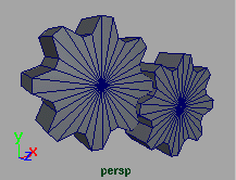
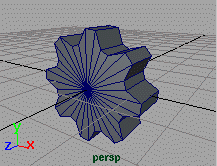
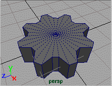
STEP ONE
Create a polygonal gear
using the steps outlined
Rotate the gear by 90
degrees around the X
axis so that it is sitting
upright.
http://www.aw.sgi.com/assistant_online/entertain/maya/how_tos/dynamics/particle_gears/ (1 of 4) [3/7/2000 14:28:55]


Assistant Online - Maya/How Tos/Dynamics/Particle Gears
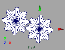
STEP TWO
Duplicate the gear.
Place the second gear so
that the cogs are linked
together. Make sure that
the surfaces are not
touching.
STEP THREE
You are now going to
create hinge constraints.
Select the first gear.
In the Dynamics menu
set, select Bodies >
Create Constraint -
options. Change the
Constraint type to
Hinge. Press Create.
Place this hinge at the center of the corresponding gear.
Select the second gear and again select Bodies > Create
constraint. Place this hinge at the center of the corresponding
gear.
Note that the gears automatically become rigid bodies when
you add a hinge to them. This will help you use them in the
particle simulation.
STEP FOUR
Select Particles > Create
Emitter, and place the
emitter above the gears.
In the Channel Box, hold
down your left mouse
button over the Emitter
Type attribute field and
select Directional. Make
sure that Direction X is set to 1 and increase the Spread to 0.5. This will point the emission towards the gears in a
spray-like form.
Play the simulation for a few frames. You can see the particles
but they are not falling to the ground. You need to add gravity.
http://www.aw.sgi.com/assistant_online/entertain/maya/how_tos/dynamics/particle_gears/ (2 of 4) [3/7/2000 14:28:55]


Assistant Online - Maya/How Tos/Dynamics/Particle Gears
STEP FIVE
Select the particles.
Select Fields > Create
Gravity. This creates a
gravity field and connects
it to the particles.
Play the simulation. Now
the particles are falling
but they may not be
hitting the gears. Reselect the emitter and adjust the Speed
attribute until the particles are landing on the gear as shown.
As the particles reach the gears, you will notice that they are
not animating. You need to make the first gear a particle
collision object.
STEP SIX
Select the first gear, excluding its
hinge. In the Channel Box, set the
Particle Collision attribute field to
on. A new collision node is created.
If you were to playback the
simulation you would see that the
particles are still not colliding with the
gear. This is because the particles
need to be connected by hand to the first gear. Setting Particle
Collision to On made collisions possible but didn't connect the particles.
STEP SEVEN
Select the particles, then the first gear. Select Particles->Make
collide.
The particles will now collide with the gear.
http://www.aw.sgi.com/assistant_online/entertain/maya/how_tos/dynamics/particle_gears/ (3 of 4) [3/7/2000 14:28:55]


Assistant Online - Maya/How Tos/Dynamics/Particle Gears
STEP EIGHT
Playback the simulation
and watch the gears turn.
To tweak the results, you
can make adjustments
such as decreasing the
Resilience or increasing
the Friction of the gears.
These attributes are
found in the
ParticleShape input nodes.
You can adjust the emitter by increasing or decreasing the rate
of emission. You can also change the mass and bounciness
attributes of the gear.
CONCLUSION
You now have particles that are driving a gear using
dynamics. That gear is in turn driving a second gear. The
hinge constraints on the two gears make sure that the gears
are rotating during the simulation. Now you can add shaders
to the various parts to put together a complete scene.
Use of this file confirms your agreement to the Terms and Conditions
set out on the Terms and Conditions page.
http://www.aw.sgi.com/assistant_online/entertain/maya/how_tos/dynamics/particle_gears/ (4 of 4) [3/7/2000 14:28:55]


Assistant Online - Maya/How Tos/Dynamics/Pendulum
Alias|Wavefront / Assistant Online / Maya / How Tos / Dynamics / Pendulum
HOW TO CREATE A
by Steve Christov
NEWTON'S PENDULUM
MAYA: Complete
Rigid Bodies
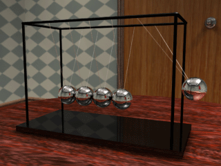
In this lesson, you will
learn how to set up rigid
bodies to create a
Newton's Pendulum.
You will use nail
constraints on a series
of spheres and apply
gravity fields to the
constraints.
Play Movie [~789kb]
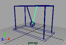
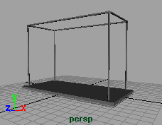
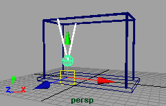
STEP ONE
Create a simple base
for the frame of the
pendulum.
To get the same results
as this how-to make the
base 10 units high and
14 units long.
Or if you like download
the file base.ma.[~85kb]
http://www.aw.sgi.com/assistant_online/entertain/maya/how_tos/dynamics/pendulum/ (1 of 5) [3/7/2000 14:29:11]


Assistant Online - Maya/How Tos/Dynamics/Pendulum
STEP TWO
Create a sphere.
Move the sphere 3
units in the Y axis.
Select Create -> CV
Curve Tool -> options.
Set the curve to be a 1
degree linear curve.
In the side view, while
holding down the x key, place a CV in the center of the sphere
and another CV at the top corner of the crossbar. Press Enter
to create the curve.
Press y to reinvoke the CV Curve tool. Create another curve
from the center of the sphere to the opposite crossbar.
Select Create -> NURBS Primitives -> Circle. Scale it down to 0.1. Using the x key, snap it to the center of the sphere.
Select the circle and while holding down the Ctrl key, select one of the curves. Select Surfaces -> Extrude -> options. In
the option box, set Result Position to At Path.
Press Extrude. Using the same circle, repeat for the other
curve.
In the Hypergraph window, delete the NURBS circle, and the
two curves.
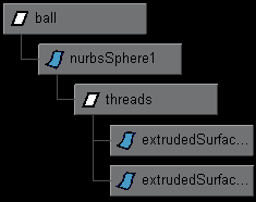
STEP THREE
Select the Sphere
and Group it to itself.
Select and Group the
two extrudes.
Rename the group for
the extrudes to
threads and the group
for the sphere ball.
Select the two groups and set the Translate X to -4.
http://www.aw.sgi.com/assistant_online/entertain/maya/how_tos/dynamics/pendulum/ (2 of 5) [3/7/2000 14:29:11]


Assistant Online - Maya/How Tos/Dynamics/Pendulum
STEP FOUR
Select the threads
and ball group nodes
and select Edit ->
Duplicate ->
options.
Change Translate X
to 2. Set the Number
of Copies to 4.
Press Duplicate and close the duplicate window.
STEP FIVE
You are now ready to
add nail constraints to
the spheres.
Select one of the
spheres.
Select Bodies ->
Create Constraint ->
options.
In the dialogue box select nail as the constraint type. This will
create a nail in the center of the sphere. With the nail still active
switch to the side view.
Select the Move tool and while pressing the x key, Move the nail so that it is positioned directly on the crossbar to the left of
the sphere. Keep in mind that the nail constraints should follow
the same path as the extrudes.
Create a Second Nail constraint for the same sphere and move it so that it is positioned on the crossbar to the right of the
sphere.
Repeat the same procedure for the remaining spheres making
sure that there are two nail constraints for each sphere.
http://www.aw.sgi.com/assistant_online/entertain/maya/how_tos/dynamics/pendulum/ (3 of 5) [3/7/2000 14:29:11]


Assistant Online - Maya/How Tos/Dynamics/Pendulum
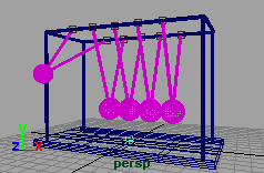
STEP SIX
You will now parent the
threads to each ball.
In the Hypergraph
window, Click and
Drag with the middle
mouse button the node
threads on to the
nurbsSphere1 icon.
Repeat for each thread
node to parent the groups to the appropriate spheres.
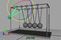
STEP SEVEN
Select the ball group
node.
Select the Rotate tool
and press Insert to
relocate the pivot
point. While pressing x
move the pivot point
up to the level of the
crossbar. Press Insert to return to the rotate tool.
Rotate along the Z axis to bring the sphere up and away from the others.
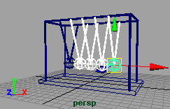
STEP EIGHT
You are now ready to
add gravity to the
spheres.
Select each sphere,
making sure that the
nail constraints are not
picked. With all five
spheres selected,
Click on Fields -> Create Gravity.
NOTE: To increase the speed of the pendulum, increase the
magnitude of gravity.
http://www.aw.sgi.com/assistant_online/entertain/maya/how_tos/dynamics/pendulum/ (4 of 5) [3/7/2000 14:29:11]


Assistant Online - Maya/How Tos/Dynamics/Pendulum
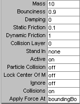
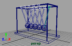
STEP NINE
With the spheres still
selected, set the following
values in the channel box.
Mass
●
= 10
Bounciness
●
= 1.0
Static Friction
●
= 0.1
Dynamic Friction
●
=
1
Set your time slider to 200
and press play.
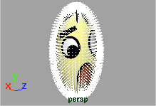
CONCLUSION
You have used some basic dynamic features to re-create
Newton's pendulum. By creating nail constraints on each
sphere you automatically turn them into rigid bodies - you can
then add gravity to create Newton's Toy!
Download the completed pendulum.ma.[~157kb]
Use of this file confirms your agreement to the Terms and Conditions
set out on the Terms and Conditions page.
http://www.aw.sgi.com/assistant_online/entertain/maya/how_tos/dynamics/pendulum/ (5 of 5) [3/7/2000 14:29:11]


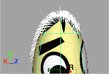
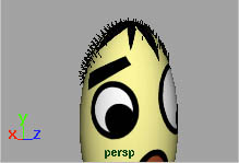
Assistant Online - Maya/How Tos/Fur/Comb Fur
Alias|Wavefront / Assistant Online / Maya / How Tos / Fur / Comb Fur
HOW TO COMB FUR
by Robert Magee
Maya Unlimited
Fur, Artisan
In this lesson you will
learn how to comb fur
using the Artisan
brushes.
You will paint several fur
attributes such as length
and baldness to add
some hair to the bouncing ball from Learning Maya. You will
also use the brush to set the direction of the hair. With Artisan
this will work just like combing your own hair.
STEP ONE
Create a NURBS primitive
Sphere and Scale it to
look like a bouncing ball.
Create and apply the
face.iff texture from project
one of Learning Maya.
Select the sphere and
select Fur > Attach Fur Description > New. Now you can see
fur indicators all over the sphere.
http://www.aw.sgi.com/assistant_online/entertain/maya/how_tos/fur/comb_fur/index.html (1 of 4) [3/7/2000 14:34:51]


Assistant Online - Maya/How Tos/Fur/Comb Fur
STEP TWO
Select the fur. In the
Channel box, select the
nurbSphere_Feedback
Shape node and set the
following:
U
●
and V samples to
50
Fur Accuracy
●
to 1
Color Feedback
●
enabled to On.
Now the display is denser and will give more visual feedback.
With larger models these settings might be too high and
interactive feedback would be compromised but for the ball it is
fine.
STEP THREE
Reselect the sphere.
Select Fur > Paint Fur
Attributes Tool - options.
This opens two windows.
From the Paint Fur Tool
Settings window, set Fur
Attribute to Baldness.
In the Tool Settings window, set the stamp profile's Value to 0
and its Opacity to 1. Click on the Flood button next to Value.
Now the sphere is totally bald.
Set the stamp profile's Value to 1 and its Opacity to 0.5. Create a Radius [u] for your brush that suits the top of the sphere then
paint the hair back onto the sphere. You are reversing the
baldness where you want the hair to be visible.
STEP FOUR
To comb the hair, you will
paint the Direction.
From the Paint Fur Tool
Settings window, set Fur
Attribute to Direction.
Zoom in and brush the
hair.
Oops! Nothing is happening. This is because the hair is
standing straight up. Therefore any changes to its direction are
not noticeable. You need to set the Fur's inclination so that the
http://www.aw.sgi.com/assistant_online/entertain/maya/how_tos/fur/comb_fur/index.html (2 of 4) [3/7/2000 14:34:51]


Assistant Online - Maya/How Tos/Fur/Comb Fur
hair is not standing up straight.
From the Paint Fur Tool Settings window, set Fur Attribute to
Inclination.
In the Tool Settings window, set the stamp profile's Value to .25
and its Opacity to 1. Click on the Flood button next to Value.
Now the fur is tilted down. You can even see some changes in
direction based on your original direction brushing.
STEP FIVE
From the Paint Fur Tool
Settings window, set Fur
Attribute to Direction.
In the Tool Settings
window, set the stamp
profile's Value to 1 and its
Opacity to 0.5.
Zoom in and brush the
hair.
STEP SIX
You will notice that it is
easy to brush the hair on
the sides but the top of the
head is difficult. This is
because the isoparm lines
meet at the top and the
direction is more sensitive.
Tip: It might be better if the isoparm "poles" were not at the top of the head. To fix this you could create a second sphere that
sits just inside the first one that holds the hair. This surface
would put the isoparm poles at the ear so that the top of the
head is easier to control.
You can now set other fur values such as length, using either
the Attribute editor or the Artisan brush. You can also set up
color for the base and tip of the hair.
CONCLUSION
This lesson introduces you to the use of Artisan tools for
combing and editing fur in Maya. You can get more in-depth
information about using fur from the Using Maya Fur manual.
http://www.aw.sgi.com/assistant_online/entertain/maya/how_tos/fur/comb_fur/index.html (3 of 4) [3/7/2000 14:34:51]


Assistant Online - Maya/How Tos/Fur/Comb Fur
Your use of this file confirms your agreement to the
Terms and Conditions set out in the Terms and Conditions page.
http://www.aw.sgi.com/assistant_online/entertain/maya/how_tos/fur/comb_fur/index.html (4 of 4) [3/7/2000 14:34:51]


Assistant Online - Maya/How Tos/Modeling/bevelCaps.mel
Alias|Wavefront / Assistant Online / Maya / How Tos / Modeling / bevelCaps.mel
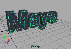
HOW TO USE THE "bevelCaps"
by Bob Gundu
MEL SCRIPT
Maya Complete
In this lesson you will
learn how to use the
bevelCaps.mel script.
This script will add planar
surfaces to the top and
bottom of the selected
bevelled surfaces. It will
also set the planar
surfaces to a high quality of tessellation to get good quality
results when rendered.
INSTALLATION
Copy the bevelCaps.mel into your scripts directory (typically $Maya/scripts). For general instructions on installing mel
scripts, see How to Use an Assistant Online mel Script .
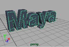
STEP ONE
Select Create > Text
-Options, and set the
following:
Text to Maya
Font to
Helvetica-Bold
Type to Curves
Press Create.
Scale X,Y,Z to 4.
http://www.aw.sgi.com/assistant_online/entertain/maya/how_tos/modeling/bevelCaps/ (1 of 2) [3/7/2000 14:35:41]


Assistant Online - Maya/How Tos/Modeling/bevelCaps.mel
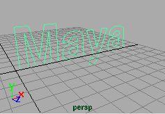
STEP TWO
With the type active,
select Surfaces > Bevel
- Options, and press
Reset, then Bevel.
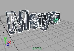
STEP THREE
You will now execute
the bevelCaps script.
Type bevelCaps into the
command line and
press Enter.
There should be
surfaces on the front
and back of the bevelled surfaces.
CONCLUSION
You should have a
good understanding of
how to use the
bevelCaps script. You
should note that
construction history on
the bevels will not
update the planar
surfaces. You will
need to reapply the script. Also, the script creates one planar
surface for the front and one for the back. The workaround for
creating a seperate face for each letter is to apply the script to
each letter seperately.
Use of this file confirms your agreement to the Terms and Conditions
set out on the Terms and Conditions page.
http://www.aw.sgi.com/assistant_online/entertain/maya/how_tos/modeling/bevelCaps/ (2 of 2) [3/7/2000 14:35:41]


Assistant Online - Maya/How Tos/Modeling/Gear
Alias|Wavefront / Assistant Online / Maya / How Tos / Modeling / Gear
HOW TO BUILD A
by Robert Magee
POLYGONAL GEAR
MAYA Complete
Polygon Modeling
In this lesson, you will
learn how to build a gear
by starting with a
polygonal cylinder then
pulling vertices to create
the final shape. You will
also learn how to
constrain grid snap
along one axis to refine
some of the points.
Play Instructional movie [~8.6 MB]
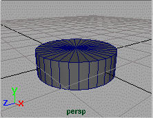
STEP ONE
Create a primitive
POLYGON cylinder.
Scale the cylinder along
the Y axis to flatten the
cylinder.
Click on the cylinder's
polyCylinder input node.
Change the number of
subdivisions to 32.
This will give us enough vertices to create 8 spokes for the
gear.
Select the cylinder and then choose Edit > Delete by Type >
History. This is very important for later when you want to
harden the edges of the polyset.
http://www.aw.sgi.com/assistant_online/entertain/maya/how_tos/modeling/gear/ (1 of 3) [3/7/2000 14:35:49]


Assistant Online - Maya/How Tos/Modeling/Gear
STEP TWO
Press F8 to go into
component mode and
make sure that the select
by Points pick mask has
been picked.
In a top view, select two
CVs then skip two CVs.
Repeat this all round the
edge of the cylinder.
STEP THREE
Select the Scale tool
then click drag on the
middle of the scale
manipulator to scale in all
directions.
Scale the vertices out
until you get the look that
you want.
STEP FOUR
Since you scaled in all
directions, the vertices at
the top and bottom of
your gear are no longer
aligned.
In a side view, select all
the vertices belonging to
the top of the gear.
STEP FIVE
Press the X key to
temporarily turn on Grid
snapping then click on
the Y axis manipulator
handle and drag the
points up. They will be all
snapped to the nearest
grid line.
Now without grid
snapping, drag the points down using the Y axis manipulator
handle to bring the points back down closer to the origin.
http://www.aw.sgi.com/assistant_online/entertain/maya/how_tos/modeling/gear/ (2 of 3) [3/7/2000 14:35:49]


Assistant Online - Maya/How Tos/Modeling/Gear
STEP SIX
Repeat the steps
outlined above to flatten
the vertices on the
bottom of the gear.
STEP SEVEN
You now want to harden
the edges of the
polymesh. Turn the
Select by Points mask
button off and turn the
Select by Lines button
on.
Click drag over the whole
gear to select all of the
poly edges. To harden the edges, select the Edit Polygons >
Normals > Soften/Harden options. Click on the All Hard
button then click on the Soft/Hard button. Now the edges will
be hard when rendered later.
CONCLUSION
You now have a poygonal gear. You have learned how to
edit vertice positions by scaling and by grid snapping while
constrained along one axis.
If you have Maya FX, you can now use this gear as part of a
particle simulation involving particle collisions and dynamic
constraints in the How to use particles to drive rigid bodies
lesson.
Use of this file confirms your agreement to the Terms and Conditions
set out on the Terms and Conditions page.
http://www.aw.sgi.com/assistant_online/entertain/maya/how_tos/modeling/gear/ (3 of 3) [3/7/2000 14:35:49]


Assistant Online - Maya/How Tos/Modeling/Nurbs Booleans
Alias|Wavefront / Assistant Online / Maya / How Tos / Modeling / Nurbs Booleans
HOW TO WORK WITH NURBS BOOLEANS
by Robert Magee
Maya Unlimited
Advanced Modeling
In this lesson you will
learn how to create
shapes using NURBS
booleans.
A NURBS boolean
operation treats two or
more surfaces like solids
then performs an
intersection and trim on the participating surfaces.
When working with booleans, the three main operations are
Subtract which removes one surface volume from another,
Intersect that creates a new shape where the two volumes
share the same space and Union which adds the two shapes
into a larger volume.
Booleans have history and can be switched from Subtract to
Intersect to Union. You can also update history by repositioning the original surfaces used to generate the boolean.
To effectively use booleans, you will also explore how the
surface's normals affects the results of the boolean.
STEP ONE
Create a NURBS Sphere
and a NURBS Cylinder.
Place the two shapes so
that they are intersecting.
http://www.aw.sgi.com/assistant_online/entertain/maya/how_tos/modeling/nurbs_boolean/ (1 of 4) [3/7/2000 14:36:01]


Assistant Online - Maya/How Tos/Modeling/Nurbs Booleans
STEP TWO
Select Edit Surfaces >
Booleans > Subtract
Tool.
Click on the sphere then
press the Enter key to
select it as the first
object.
Click on the cylinder
then press the Enter key to select it as the second object. The
shapes are subtracted and the sphere now has the cylinder
removed from its surface.
Note: If you added color in Step One to the two parts, you will
notice that the color disappears. In fact the boolean operation
has produced two new surfaces that will need to have shaders
reapplied. In some cases more than two new surfaces may be
produced.
STEP THREE
The boolean does use
history which can be
updated. The first
method for updating
history is to choose
another boolean
operation from the
Channel box.
Click on the boolean input node in the Channel box. Set
Operation to Intersect.
Now the resulting shape shows the volume that is shared by
the cylinder and the sphere.
STEP FOUR
Select one of the boolean surfaces then click on the boolean
input node in the Channel Box.
In the Hypergraph, select the hidden nurbs sphere node. Move
the sphere to update the history on the shape. You can even
animate these hidden shape nodes although they will slow
down interactive feedback when you playback the scene.
http://www.aw.sgi.com/assistant_online/entertain/maya/how_tos/modeling/nurbs_boolean/ (2 of 4) [3/7/2000 14:36:01]


Assistant Online - Maya/How Tos/Modeling/Nurbs Booleans
STEP FIVE
Another issue that
affects how booleans
operate is the surface's
normals. By using a
plane, you can see how
Maya treats any surface
as if it is a volume when
performing booleans.
Start a new scene.
Create a NURBS Primitive plane. Go into component mode
and pull the middle two rows of CVs up to add curvature to the
surface.
STEP SIX
Create a NURBS
sphere that intersects
the plane.
Duplicate both the
sphere and the plane
and move them to the
side.
STEP SEVEN
Select both of the plane
surfaces and select
Display > NURBS
Components >
Normals. Be sure that
you are in shaded mode.
Lines protrude out from
the surface to indicate
the surface's normal
direction.
Select one of the surfaces and select Edit Surfaces > Reverse Surface Direction. Now this surface's normals are going in the
opposite direction.
http://www.aw.sgi.com/assistant_online/entertain/maya/how_tos/modeling/nurbs_boolean/ (3 of 4) [3/7/2000 14:36:01]


Assistant Online - Maya/How Tos/Modeling/Nurbs Booleans
STEP EIGHT
Select Edit Surfaces >
Booleans > Subtract
Tool.
Click on one of the
spheres then press the
Enter key to select it as
the first object.
Click on the corresponding plane then press the Enter key to select it as the second object. The shapes are subtracted and
the sphere now has the cylinder removed from its surface.
Repeat these steps for the other sphere/plane combination.
You will notice that in the results are the opposite. This is
because the side of the surface that shows the normals is seen
as the "outside" of the surface volume while the opposite side is the "inside". Therefore the "inside" of the surface volume is subtracted from the sphere in both cases.
CONCLUSION
Booleans are a great tool for quickly bringing together NURBS
shapes into a series of trimmed surfaces. Make sure that trims
are what you need for your model since they can break apart if
the surfaces are deformed.
Use of this file confirms your agreement to the Terms and Conditions
set out on the Terms and Conditions page.
http://www.aw.sgi.com/assistant_online/entertain/maya/how_tos/modeling/nurbs_boolean/ (4 of 4) [3/7/2000 14:36:01]


Assistant Online - Maya/How Tos/Modeling/Spiral Staircase
Alias|Wavefront / Assistant Online / Maya / How Tos / Modeling / Spiral Staircase
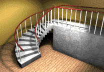
HOW TO BUILD A SPIRAL STAIRCASE
by Robert Magee
Maya Complete
Modeling
In this lesson, you will learn
how to build a spiral
staircase using polygon
booleans and a bend
deformer.
This lesson highlights how
deformers can be used to
enhance the modeling
process.
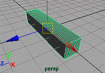
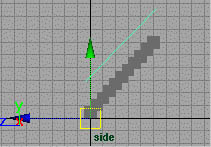
STEP ONE
Select Create > Polygons
Primitives > Cube.
In the Channel box, set the
cube's width to 5 and its
subdivisionsZ to 10.
Move the cube so that it is
sitting on the ground plane.
This cube will act as the first tread of the staircase. The
subdivisions will help ensure a smooth bending later.
http://www.aw.sgi.com/assistant_online/entertain/maya/how_tos/modeling/spiral_stair/ (1 of 5) [3/7/2000 14:36:12]


Assistant Online - Maya/How Tos/Modeling/Spiral Staircase
STEP TWO
Select Edit > Duplicate >
options.
Set Smart Transform to
On. This option will allow
you easily create multiple
duplications. Click the
Duplicate button.
In the side view, Move the duplicated cube up and to the right.
This will be the second tread.
Note: Do not de-select the cube. If you do, Smart Transform
will lose the offset information it needs to produce the
duplicates created in the next step.
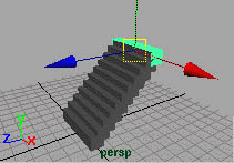
STEP THREE
Press Ctrl - d. This will
create another duplicate
that is offset by the same
amount as the second
tread.
Press Ctrl - d eight more
times to create the treads
of the stair.
You now have several cubes that are all separate shapes. You
will need to use polygonal booleans to create a single surface
for the stair.
STEP FOUR
Select the first two treads.
Select Polygons >
Booleans > Union. They
are now one shape.
Note: you can only join two
polysets at a time. Now
you have to add the other
treads.
Press the shift key then add the third tread to the selection.
Press the g key to repeat the boolean union. Repeat these
steps until all the treads are combined into a single polyset.
The various booleans have added history to the staircase that
is not needed. Select the polyset then select Edit > Delete by Type > History to remove the extra input nodes.
http://www.aw.sgi.com/assistant_online/entertain/maya/how_tos/modeling/spiral_stair/ (2 of 5) [3/7/2000 14:36:12]


Assistant Online - Maya/How Tos/Modeling/Spiral Staircase
STEP FIVE
Select Create > EP Curve
Tool. In the side view,
draw a single span curve
where you would want to
place a handrail.
Select Edit Curves >
Rebuild Curves -
options. Set Number of Spans to 20. Click Rebuild. This will add enough CVs to ensure a good bending when you add the
deformer later.
In the top view, place one curve at one side of the stair and
then duplicate the curve to create a second handrail at the
other side of the stair.
Note: You have built a curve for the handrail so that you can
extrude a profile after the bending. Building the handrail as a
surface would add too much distortion after bending.
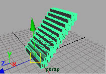
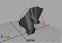
STEP SIX
Select the curves and the
stair polyset.
Select Deform > Create
Nonlinear > Bend -
options. Set Curvature to
4 then click on the Create
button. This gives you a
sideways bend that doesn't look like a staircase.
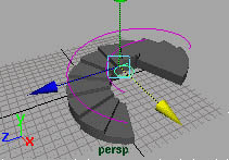
STEP SEVEN
In the Channel box, set the
bendHandle's rotateX to
90. This reorients the
deformer to create more of
a stair shape.
With the Move tool, move
the bendHandle along the
X axis to widen the bend. Now the handrail curves and the
treads are bending nicely into a spiral stair.
http://www.aw.sgi.com/assistant_online/entertain/maya/how_tos/modeling/spiral_stair/ (3 of 5) [3/7/2000 14:36:12]


Assistant Online - Maya/How Tos/Modeling/Spiral Staircase
STEP EIGHT
In the Channel box, click
on the bend Input node.
Now select the Show
Manipulator tool. You can
drag on the curvature
handle to adjust the
amount of curve in the
bend.
Note: You can also
animate the bending of the stair by setting keys on the
curvature attribute.
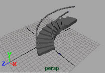
STEP NINE
To create the handrail
surfaces, create a
primitive circle and scale it
to a reasonable radius.
Select the circle and then
one of the handrail curves.
The path curve for an
Extrusion must be picked last.
Select Surfaces > Extrude - options. Set Result Position to At Path and Pivot to Component. Click Extrude and the handrail will be placed on the handrail curve. Repeat for the
other handrail.
Tip: If history is maintained as you extrude then you can later
select the circle and scale it. The two handrail surfaces will
update to show the new profile radius. This lets you evaluate
the profile size after extruding to see it in context.
CONCLUSION
The bend deformer has made it easy to build a spiral staircase
with handrails. You can now delete history or choose to keep it
around in case you want to update some part of the model.
Download a finished scene file:
Your use of this file confirms your agreement to the
Terms and Conditions set out in the Terms and Conditions page.
http://www.aw.sgi.com/assistant_online/entertain/maya/how_tos/modeling/spiral_stair/ (4 of 5) [3/7/2000 14:36:12]


Assistant Online - Maya/How Tos/Modeling/Spiral Staircase
http://www.aw.sgi.com/assistant_online/entertain/maya/how_tos/modeling/spiral_stair/ (5 of 5) [3/7/2000 14:36:12]


Assistant Online - Maya/How Tos/Modeling/Square Surfaces
Alias|Wavefront / Assistant Online / Maya / How Tos / Modeling /Square Surfaces
HOW TO WORK WITH SQUARE
by Robert Magee
SURFACES
Maya Unlimited
Advanced Modeling
In this lesson, you will
build two surfaces using
the Square tool. You will
learn how to create a
square surface using four
boundary curves, and a
square surface that
maintains continuity with a
neighboring surface.
STEP ONE
Select Create > EP (Edit
Point) Curve Tool. Draw
a single span curve along
the Z axis.
Duplicate the curve and
Move it forward along the
X axis.
STEP TWO
Select Create > EP (Edit
Point) Curve Tool. Press
the c key to use curve
snapping and click drag on
the first curve until you
place a point at the end of
the curve. Use this
snapping to place a
second point at the end of
the other curve.
http://www.aw.sgi.com/assistant_online/entertain/maya/how_tos/modeling/square_surface/ (1 of 4) [3/7/2000 14:37:07]


Assistant Online - Maya/How Tos/Modeling/Square Surfaces
Press the Enter key.
Repeat to add a single span curve to the other end of the initial
curves. Be sure to use curve snapping to place all the points
since the Square tool requires intersecting curves to work
properly.
STEP THREE
Select the front curve and
the two side curves. Press
F8 to go into component
mode.
Select all the CVs on the
front curve and the two
end CVs of the side
curves.
Move the CVs down along the Y axis. This will add some
curvature to the shape you are creating.
By moving the end CVs of the side curves, you make sure that
they are still intersecting the front curve.
STEP FOUR
Press F8 to go back to
object mode. Click in
space to deselect the
curves.
Select the four curves in
either a clockwise or
counterclockwise
direction. They must be
selected in some order for the Square tool to work properly.
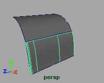
Select Surfaces > Square. Press the 3 key to increase the surface's display smoothness.
The surface is created so that it touches all the boundary
curves. You are now going to build a second square surface
that uses the first surface for one of its edges.
http://www.aw.sgi.com/assistant_online/entertain/maya/how_tos/modeling/square_surface/ (2 of 4) [3/7/2000 14:37:07]


Assistant Online - Maya/How Tos/Modeling/Square Surfaces
STEP FIVE
Duplicate the front curve
that was used to build the
surface. Move it forward
and down in front of the
first surface.
Create two more single
span edit point curves to
create a boundary for a
new surface. Use curve snapping to help you.
STEP SIX
Click on the first surface
with your right mouse
button and select Isoparm
from the marking menu.
Click on the edge isoparm
that makes up the top
edge of the new boundary.
It will highlight in yellow
when it is selected.
Press the shift key and select the other three curves in
clockwise or counter clockwise order.
Select Surfaces > Square. Press the 3 key to increase the surface's display smoothness.
You can now see a surface but the surface is not created with a
clean topology. You will try and find out why this is happening.
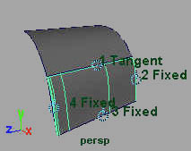
STEP SEVEN
With the new surface
selected and its squareSrf
input node highlighted in
the Channel box, select
the Show Manipulator
tool.
Manipulators appear that
show the continuity
condition at the edges which are numbered in the order you
picked them.
Fixed means that the surface is meant to match the
neighboring curve or surface based on the edge position.
Tangent means that the surface will match the neighboring
surface based on its tangency. This will make the surfaces
appear to flow together.
http://www.aw.sgi.com/assistant_online/entertain/maya/how_tos/modeling/square_surface/ (3 of 4) [3/7/2000 14:37:07]


Assistant Online - Maya/How Tos/Modeling/Square Surfaces
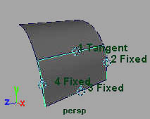
The original single span curves should produce single span
surfaces but the new surface has extra isoparm spans. If you
zoom in closer, the surface is also not conforming to the two
side curves. This is because the side curves were not tangent
to the first surface. Therefore the new surface had to add
isoparm spans and break away from the side curves in order to
meet the tangency requirement at Edge 1.
STEP EIGHT
Select the first surface
and one of the side
curves.
Select Edit Curves >
Project Tangent. Now the
curve should be tangent to
the surface. Construction
history on the second
square surface will update it's topology as the curve is fixed.
Note: You may have to change the projectTangent node's
Tangent Direction in the Channel box from U to V depending
on the order in which you chose the curves to build the first
surface.
Repeat for the other side curve. Now if you select the second
square surface, you will see that it is a single span in both
directions. Also it is not breaking away from the side curves
since they now all follow the same rules of tangency.
CONCLUSION
By using the edge of one or more surfaces to help build another
surface, the Square tool's tangent continuity capabilities can
come into play. By building clean curves as boundary curves
then making sure that those curves also maintain tangency with
related surfaces, you can build up a patchwork of surfaces that
all appear to work as a single surface.
Use of this file confirms your agreement to the Terms and Conditions
set out on the Terms and Conditions page.
http://www.aw.sgi.com/assistant_online/entertain/maya/how_tos/modeling/square_surface/ (4 of 4) [3/7/2000 14:37:07]