


Assistant Online - Maya/How Tos/Paint Effects/Tree
Alias|Wavefront / Assistant Online / Maya / How Tos / Paint Effects / Tree
HOW TO CREATE A TREE
By Steve Christov
IN PAINT FX
Maya 2.5 Complete
Paint Effects
In this lesson you will
create a tree in Paint
Effects starting from a
simple black brush
stroke.
While this approach is
somewhat drastic it will
help you form a good
understanding of the
attributes that make up
Paint Effects.
This article assumes you have Paint Effects loaded into Maya.
Please see the Maya help menu on how to install Paint Effects
if you have not already done so.
This lesson is the third of a three part lesson. You may want to
complete parts one " How to create a realistic sky using EnvSky"
and two " How to create realistic shadows using EnvSky" before you start this lesson.
STEP ONE
Download and open the
scene
Env_sky_shadow. If you have completed the
previous lessons, you
can use your last saved
scene file.
Delete the sphere.
Select the lights, 3D env_sky icon, and the 3D texture icon for the cloud.
Select Display > Hide > Hide Selection. This will unclutter the http://www.aw.sgi.com/assistant_online/entertain/maya/how_tos/paintFX/tree/index.html (1 of 8) [3/7/2000 14:39:14]

Assistant Online - Maya/How Tos/Paint Effects/Tree
scene so we can concentrate on the Paint Effects stroke.
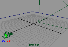
STEP TWO
Switch to the Persp
window. Select the
plane and select the
Paint Effects > Make
Paintable.
Open the Visor by
selecting Windows >
Visor. Scroll to the
bottom and open the section marked Brushes. This will give
you access to the Paint Effects preset brushes.
Open the Pens and select the simpleLine brush.
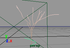
In your perspective window, Paint a small stroke near the
origin.
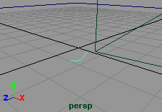
STEP THREE
With the stroke still
selected, open the
Attribute Editor. Open
the tab simpleLine1.
Your first step is to add
tubes to the brush.
Open the tubes section
and Click beside
Tubes and then Tube Completion.
Open the Tubes > Creation section. Change the Tubes Per Step to 0.1 and the Tube Rand attribute to 0. Also change the Length Min to 0.8, and the Length Max to 0.9.
You will also see some attributes called Tube Width1 and 2.
These set the width for the base of the tube and the tip of the
tube respectively. Change the Tube Width1 to 0.12 and Tube Width2 to 0.09. There are settings for randomness and bias
for multiple tubes across the same stroke but because we are
only creating one tube, we can ignore these settings.
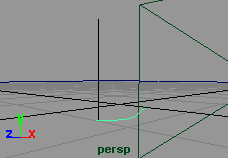
Change the number of Segments to 40. This will increase the
number of segments that are used to create the tube.
The Elevation attribute dictates the lean on the tube. Where 0
is the tube lying flat against the curve and 1 standing straight
up. Since you want the tree to stand straight up, set the
Elevation Min and Max to 1.0.
NOTE: You may notice that your tube is still lying flat against
the curve despite changing the elevation attribute. You can fix
http://www.aw.sgi.com/assistant_online/entertain/maya/how_tos/paintFX/tree/index.html (2 of 8) [3/7/2000 14:39:14]

Assistant Online - Maya/How Tos/Paint Effects/Tree
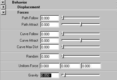
this in the attribute editor. Open Behavior > Forces. Change
the Path Follow to 0.0.
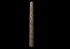
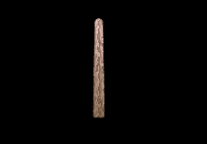
STEP FOUR
Now that you have the
basic shape of the
trunk you are now
ready to shade it.
Open the Shading
section in the Attribute
Editor. Click on the
color swatch next to
Color1. In the color chooser change the RGB values to 0.64,
0.52, 0.41.
Open the Tube Shading section. Click on the color swatch
next to Color2. Set the RGB values to 1.0, 0.85, 0.83.
You have now set the colors for the trunk of your tree. If you
render now you will see that it will render out in one uniform
color. By adding a simple ramp texture to the tube you can
simulate bark.
Open the Texturing section. Click on the icon next to Map Color. We are going to map a V Ramp to the trunk of the
color to give the appearance of bark.
From the drop down menu beside Texture Type, Select V
Ramp. Set the following attributes:
● Texture2 Color to RGB 0.54, 0.49, 0.44
Repeat U
●
to 6.0
Repeat V
●
to 2.2
Blur Mult
●
to .26
Smear
●
to 0.203
Smear V
●
to 0.61
You can preview the progress this far by pressing the hotkey
" 8" while in the persp window to switch to the paint effects preview render window. In the menu select Stroke Refresh >
Rendered. However it will take longer to refresh with each
change.
NOTE: When you render, depending on the length of your
original stroke, you may have more than one tube attached to
your stroke. One way to solve this is to lower the Tubes per
Step attribute in the Tubes > Creation section.
http://www.aw.sgi.com/assistant_online/entertain/maya/how_tos/paintFX/tree/index.html (3 of 8) [3/7/2000 14:39:14]


Assistant Online - Maya/How Tos/Paint Effects/Tree
STEP FIVE
In Paint Effects you
have the option to
Illuminate the tree with
simulated or real lights.
Open the Illumination
section, Check the box
next to Illuminated. This
will use real lights from
your scene on your paint effects tree.
We are also going to add some specular qualities to the tree to
give it some highlights. Set Specular to 0.15.
STEP SIX
Now that we have the
trunk, we are ready to
add some branches.
Open the Tubes Growth
section and click next
to Branches to add
them to the trunk.
Open the Branches section. Increase the Split Max Depth to 7. This increases the number of times the branch will split up.
Increase the Branch Dropout to 0.02.
The next set of values control different attributes for the split on
the branch including Randomness, Angle of split, Twist. Feel
free to experiment with these values and come up with your
own style of tree or you can set the following values:
● Split Rand to .017
Split Angle
●
to 26.3
Split Twist
●
to 0.32
Split Size Decay
●
to 0.67
Split Bias
●
to 0.19
http://www.aw.sgi.com/assistant_online/entertain/maya/how_tos/paintFX/tree/index.html (4 of 8) [3/7/2000 14:39:14]

Assistant Online - Maya/How Tos/Paint Effects/Tree
STEP SEVEN
Click on the box next to
Twigs to turn them on.
Open the twigs section.
Set the Num Twig
Clusters to 8.0 and set
the Twig Dropout to
0.439.
Then next attribute set length, width,angle and twist. Again feel
free to experiment with the settings to get your own tree or set
the following attributes:
Twig Length
●
to 0.08
Twig Base Width
●
to 0.7
Twig Tip Width
●
to 0.15
Twig Angle1
●
to 52.5
Twig Angle2
●
to 54.0
Twig Twist
●
to 0.512
Keep in mind that your
twigs will decide the
placement of leaves. So
these settings can have a
pretty dramatic effect
down the line. For
example increasing the
number of Twig Clusters
will result in more leaves on your final tree.
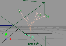
STEP EIGHT
You will now add some
leaves to the tree to
complete the look.
Click the box next to
Leaves. Set the
following attributes:
Leaves in
●
Cluster to 5.0
Num Leaf
●
Clusters to 4.0
Leaf Dropout
●
to
0.154
Leaf Length
●
to
0.04
Leaf Base Width
●
to 0.035
Leaf Tip Width
●
http://www.aw.sgi.com/assistant_online/entertain/maya/how_tos/paintFX/tree/index.html (5 of 8) [3/7/2000 14:39:14]


Assistant Online - Maya/How Tos/Paint Effects/Tree
to 0.01
Leaf Start
●
to 0.9
● Leaf
Twist
to
0.5
Leaf
●
Translucence to
0.561
Leaf Sat Rand
●
to
0.033
Leaf Val Rand
●
to
0.114
Check the box next to Terminal Leaf. This will place a leaf at the end of each twig.
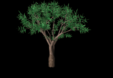
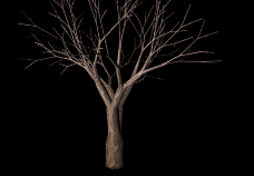
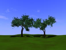
STEP NINE
If you render your
image at this point
you should have a
basic looking tree.
You are now ready to
add various other
attributes to further
enhance your tree.
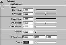
In the Attribute Editor open the Behavior Forces section. Set
the Gravity slider to 0.05. You will notice that the branches and leaves out as if the weight of the leaves was pulling the
branches down.
http://www.aw.sgi.com/assistant_online/entertain/maya/how_tos/paintFX/tree/index.html (6 of 8) [3/7/2000 14:39:14]


Assistant Online - Maya/How Tos/Paint Effects/Tree
STEP TEN
You are now ready to
add some animation to
the tree to simulate it
swaying in the wind.
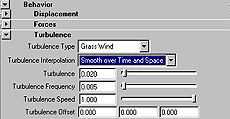
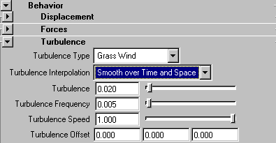
Open the Behaviour
then the Turbulence section. Set the Turbulence Type to
Grass Wind. Set Turbulence Interpolation to Smooth over
Time and Space.
Because we are going to use this tree with a time lapse sunset,
you will want the tree to behave with tight motion in the tree
trunk and branches but you do want the the leaves to give the
impression of some quick fluttering in the wind. Set the
following values:
● Turbulence to 0.02
Turbulence Frequency
●
to 0.005
Turbulence Speed
●
to 1.0
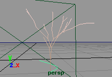
Set the Time Slider to 100. Press Play. Switch to the Perspective window. The wireframe will give you an indication
of the general motion of the tree.
STEP ELEVEN
You will now save your
brush to the visor so
you can access it in the
future. With the tree
selected, go to Paint
Effects > Get Settings
from Selected Stroke.
This will apply your tree
to the template brush.
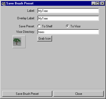
Now Select > Paint
Effects >Save Brush
Preset.
Set the Label and Overlay Label to Mytree.
Save it To Visor and set the Visor Directory to Trees.
Click on Grab Icon and drag around your tree in the render
view to make an icon for you brush.
Click Save Brush Preset.
http://www.aw.sgi.com/assistant_online/entertain/maya/how_tos/paintFX/tree/index.html (7 of 8) [3/7/2000 14:39:14]


Assistant Online - Maya/How Tos/Paint Effects/Tree
STEP TWELVE
Select Panels >
Perspective > Camera
1.
Position your tree in the
frame by selecting the
stroke and moving it
with the manipulator.
Add a texture to the
ground plane.
Do some test renders at different frames to make sure you are
happy with the framing and lighting. When you are satisfied
with the results, set the render globals to render the animation
for 100 frames from Camera1.
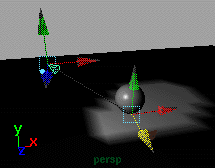
CONCLUSION
You have now
assembled a complete
scene similar to the one
above. By this point you
have learned how to
create and use an
environment sky, add a
light to it to simulate
realistic shadows based
on the sun position, and
made your own tree in
paint effects.
Enhance your scene by sculpting the floor surface with Artisan
to make some nice rolling hills and adding some grass strokes
to it.
Download the completed scene file. [~100k]
Use of this file confirms your agreement to the Terms and Conditions
set out on the Terms and Conditions page.
http://www.aw.sgi.com/assistant_online/entertain/maya/how_tos/paintFX/tree/index.html (8 of 8) [3/7/2000 14:39:14]
http://www.aw.sgi.com/assistant_online/entertain/maya/how_tos/paintFX/tree/img/nine.gif http://www.aw.sgi.com/assistant_online/entertain/maya/how_tos/paintFX/tree/img/nine.gif [3/7/2000 14:39:30]
http://www.aw.sgi.com/assistant_online/entertain/maya/how_tos/paintFX/tree/img/ten.gif http://www.aw.sgi.com/assistant_online/entertain/maya/how_tos/paintFX/tree/img/ten.gif [3/7/2000 14:39:32]
http://www.aw.sgi.com/assistant_online/entertain/maya/how_tos/paintFX/tree/img/eleven.gif http://www.aw.sgi.com/assistant_online/entertain/maya/how_tos/paintFX/tree/img/eleven.gif [3/7/2000 14:39:34]


Assistant Online - Maya/How Tos/Rendering/Animate Textures
Alias|Wavefront / Assistant Online / Maya / How Tos / Rendering / Animate Textures
HOW TO ANIMATE TEXTURE FILES
by Bob Gundu
MAYA: Base
Rendering
This lesson will
demonstrate how to use
a numbered sequence of
images as a texture map.
There are basically two
methods to achieve this
effect; expressions, and
keyframing. Both will be
covered in this lesson.
Note: Before beginning this how-to, you need to have ready a
sequence of frames with a numbered extension such as
filename.rgb.001, im.001, or f ilename.sgi.01. These frames will be used as the animated texture map.
Tip: Check the images directory in your favorite Maya project
for rendered frames that you can use with this how-to.
STEP ONE
In the Multilister, create a File texture node and open the
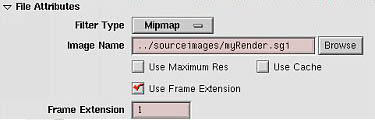
Attribute Editor for the File node. In the Attribute Editor set the following:
In the
●
File Attributes section, use the Browse button or
enter in the field the location and name of the sequence
of images. Be sure not to include the extension. For
example, if the first frame is named "myRender.sgi.001",
you should only enter "myRender.sgi".
Change
●
Use Frame Extension to On.
http://www.aw.sgi.com/assistant_online/entertain/maya/how_tos/rendering/animated_texture_files/ (1 of 5) [3/7/2000 14:42:01]

Assistant Online - Maya/How Tos/Rendering/Animate Textures
METHOD 1:
KEYFRAMING
This method requires a
keyframe for the
beginning and the end of
the sequenced images.
Go to frame
●
1 (or
to the frame where
you want the
texture to begin
animating).
With the
●
file1
texture selected,
open the Attribute
Editor (or go to the
Channel Box) and,
in the Frame
Extension field,
enter the extension
number of the
frame where you
want the texture to
begin animating.
(e.g. if your images
are named
sequentially
filename.rgb.8
through
filename.rgb.35,
enter "8")
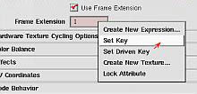
With the
●
RMB over
the Frame
Extension
attribute, select Set
Key if using the
Attirbute Editor ( or
Key Selected if
using the Channel
Box) from the
pop-up window.
http://www.aw.sgi.com/assistant_online/entertain/maya/how_tos/rendering/animated_texture_files/ (2 of 5) [3/7/2000 14:42:01]
Assistant Online - Maya/How Tos/Rendering/Animate Textures
In the Timeline, go
●
to the last frame for
the texture file
animation.
Enter the the last
●
extension number
from your
sequence of
images in the
Frame Extension
field. (e.g. if your
images named
filename.rgb.8
through
filename.rgb.35,
enter 35)
Set another key
●
with the RMB over
the Frame
Extension field.
Connect the
●
texture file to a
shading group and
assign it to a
surface.
If you scroll through or playback your animation, you will notice
that the file textures are updating.
Tip: Ensure that your animation curve tangents are set to linear for each keyframe, and that your animation preference for
playback is set to Free.
METHOD 2:
EXPRESSIONS
You can also animate
texture files using an
expression, achieving
the same result as in
Method 1 but without
using key frames.
If you have already
completed Method 1,
you can with the RMB
over the Frame
Extension field, select
Break Connection and
http://www.aw.sgi.com/assistant_online/entertain/maya/how_tos/rendering/animated_texture_files/ (3 of 5) [3/7/2000 14:42:01]

Assistant Online - Maya/How Tos/Rendering/Animate Textures
continue with this
method.
With the RMB over the
Frame Extension field,
select Create New
Expression... from the
pop-up menu to display
the Expression Editor.
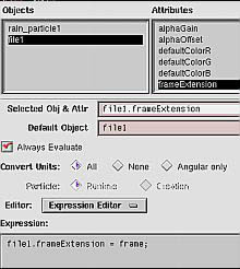
In the Expression Editor,
complete the following
steps:
In the
●
Attributes
column select
FrameExtension.
In the
●
Expression
field enter the
following:
file1.frameExtension
= frame;
Press
●
Create.
The above expression assumes your file textures sequence
begins with the extension ".1" (e.g. myRender.rgb.1). If your source images sequence starts with anything other than ".1",
you'll need to edit the expression as follows:
file1.frameExtension = frame + 7;
This means that, similar to the example given in our keyframing
method where the images are numbered filename.rgb.07
through filename.rgb.35, the system will read "frame" as
" myRender.rgb.1", then add 6 more frames and start animating the file texture at " myRender.rgb.8".
Note: If you had already created other file nodes, your file texture name may be something other than file1. If this is the
case, use the name that appears in your session.
Connect the texture file to a shading group and assign it
●
to a surface
If you scroll through or playback your animation, you will notice
that the file textures are updating.
http://www.aw.sgi.com/assistant_online/entertain/maya/how_tos/rendering/animated_texture_files/ (4 of 5) [3/7/2000 14:42:01]


Assistant Online - Maya/How Tos/Rendering/Animate Textures
CONCLUSION
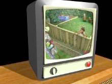
The example of the
television is only one
way of using an
animated texture map.
Another possibility is
using it for animating
fast moving objects like
rotating tires and
helicopter blades which
have extreme motion
blur. The animated
texture maps could already include a blurred look to
decrease rendering time.
The keyframing method is a flexible and straight forward
approach to animating a texture map. With this method,
cycling the texture map can be achieved in the Graph Editor.
To do the same with method 2 requires a slightly more
advanced expression.
Use of this file confirms your agreement to the Terms and Conditions
set out on the Terms and Conditions page.
http://www.aw.sgi.com/assistant_online/entertain/maya/how_tos/rendering/animated_texture_files/ (5 of 5) [3/7/2000 14:42:01]


Assistant Online - Maya/How Tos/Rendering/Combine Map
Alias|Wavefront / Assistant Online / Maya / How Tos / Rendering / Combine Maps HOW TO COMBINE BUMP
by Lorna Saunders
& DISPLACEMENT MAPS
Maya Complete
Rendering
In this lesson, you will
learn how to combine a
displacement map and
bump map to create a
brick texture. You will also
learn how to use the
Connection Editor to
connect hidden attributes as you build a textured brick wall.
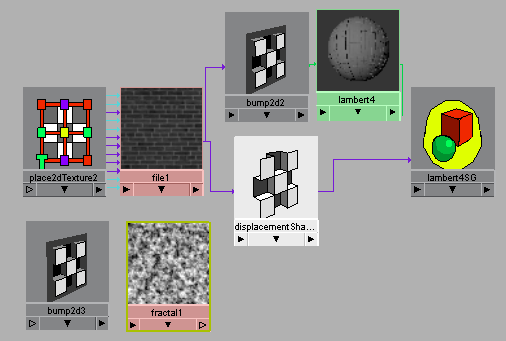
To achieve both a displaced and bumped surface, you will start
by displacement mapping the shading group with a file texture.
You will notice that this process also maps the bump channel
automatically with the same file texture. Later, a fractal will
serve as a new bump map "chained" to this first bump in the
dependency graph. This approach gives you the combined look
of both the displacement and the bump map qualities on the
shading group.
STEP ONE
Open the Hypershade and
create a Lambert material
node with a shading group.
Click the show Up and
Downstream Connections
icon in the Hypershade to
display the shading group
node. Name this shading
group WallSG.
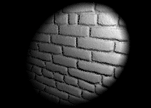
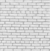
Open up the Attribute
editor and click on the
WallSG tab. Map the displacement channel on this shading
group with a grayscale brick file texture like the one shown
here.
http://www.aw.sgi.com/assistant_online/entertain/maya/how_tos/rendering/bump_displacement/ (1 of 4) [3/7/2000 14:42:13]


Assistant Online - Maya/How Tos/Rendering/Combine Map
STEP TWO
Assign the shading group
to a plane and rotate it 90
degrees around the X axis.
Add a spotlight to
illuminate the wall.
Render the scene to see
the displaced effect.
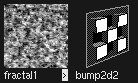
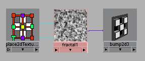
STEP THREE
In the Hypershade, create two new
nodes using Create -> Create
Render Node.
Under the texture tab of the Create Render Node window,
create a 2D Fractal texture. Under the Utilities tab, create a
Bump 2D node.
You will be layering these with the displacement map to give
the brick a rougher look.
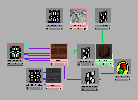
STEP FOUR
In the Hypershade clear the
view in the work area. With
your MMB, drag the WallSG,
the 2Dbump, and the fractal
nodes from the Visor into the
Hypershade view.
You will be building the rest
of this shading network in the
Hypershade.
STEP FIVE
In the Hypershade, drag the fractal node onto the new bump2d
node. The default connection (outAlpha to bumpValue) is made
automatically in this case.
http://www.aw.sgi.com/assistant_online/entertain/maya/how_tos/rendering/bump_displacement/ (2 of 4) [3/7/2000 14:42:13]


Assistant Online - Maya/How Tos/Rendering/Combine Map
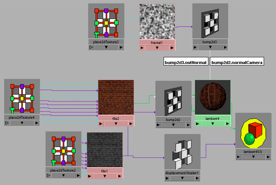
STEP SIX
Drag the bump2d node onto
the bump2d node that is
already part of the WallSG
shading group. The
Connection Editor opens.
On the left side click on Out
Normal. Go to the Right
Side Filters menu and turn
on Show Hidden. Click on
Normal Camera.
This creates a connection between the two bump nodes. Be
sure that you have Auto-connect turned on under the options
menu in the Connection Editor to make connections this way.
STEP SEVEN
Select the second bump2d
node that you just
connected into the shading
group. Open the Attribute
editor and change the
Bump Depth to about 0.2.
Render your scene again
to see the effect of this
new bump added to the WallSG.
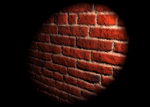
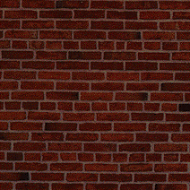
STEP EIGHT
Map an image like the
one shown here to the
color channel of the
material on the WallSG to
complete the look of the
brick wall.
http://www.aw.sgi.com/assistant_online/entertain/maya/how_tos/rendering/bump_displacement/ (3 of 4) [3/7/2000 14:42:13]


Assistant Online - Maya/How Tos/Rendering/Combine Map
STEP NINE
Render your scene again
to see the completed
brick wall.
CONCLUSION
You have learned how to create a shading group that has
both a displacement map and a bump map by chaining two
bump nodes together.
Use of this file confirms your agreement to the Terms and Conditions
set out on the Terms and Conditions page.
http://www.aw.sgi.com/assistant_online/entertain/maya/how_tos/rendering/bump_displacement/ (4 of 4) [3/7/2000 14:42:13]
http://www.aw.sgi.com/assistant_online/entertain/maya/how_tos/rendering/bump_displacement/img/step4_lrg.gif http://www.aw.sgi.com/assistant_online/entertain/maya/how_tos/rendering/bump_displacement/img/step4_lrg.gif [3/7/2000 14:42:16]
http://www.aw.sgi.com/assistant_online/entertain/maya/how_tos/rendering/bump_displacement/img/step6_lrg.gif http://www.aw.sgi.com/assistant_online/entertain/maya/how_tos/rendering/bump_displacement/img/step6_lrg.gif [3/7/2000 14:42:22]


Assistant Online - Maya/How Tos/Rendering/Camera Cuts
Alias|Wavefront / Assistant Online / Maya / How Tos / Rendering / Camera Cuts
HOW TO ANIMATE CAMERA CUTS
by Robert Magee
Maya Complete
Rendering
When animating, you
may want to be able to
cut between several
cameras that look at
your scene from different
points of view. In this
lesson, you will learn
how to use the
cameraMain.mb camera
Play Movie [~407kb]
to cut between other
cameras in the scene.
The camera cut file is included inside cameraMain.ma.
The cameraMain camera is a pre-made camera that has an
expression which lets it mimic the qualities of the other
cameras in the scene, based on a cameraNumber attribute
that you can animate. Note: This expression has been updated
for Maya 2.0.
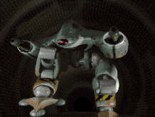
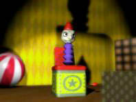
This lesson uses a scene of a robot in a tunnel to show you
how the camera cuts can be animated using this camera.
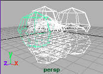
STEP ONE
Create several cameras
in your scene. Make
sure that they are named
camera1, camera2 etc.
The naming is important
to ensure they work with
the camera cut
expression later.
You can now position
and animate these
cameras to view your scene.
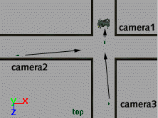
For the Gunbot scene, camera1 was set up to use an
http://www.aw.sgi.com/assistant_online/entertain/maya/how_tos/rendering/camera_cuts/ (1 of 3) [3/7/2000 14:42:30]

Assistant Online - Maya/How Tos/Rendering/Camera Cuts
expression so that it moved along the z axis as the robot walks,
camera2 is animated to move slowly down the tunnel while
viewing the robot from a distance, and camera3 is waiting
around the corner. This camera is also animated to react when
the robot shoots at it. Each of these cameras represents a
different point of view of the scene.
STEP TWO
Import cameraMain.mb. This
file contains a new camera that
uses the camera cut
expression. If you want to build your own camera cut camera,
or if you want to understand how the cameraMain camera
works, review the How to create a camera cut camera lesson.
Note: If you look through cameraMain and cameraNumber is referencing a camera that hasn't been created, then
cameraMain will go to a default position at the origin. This
behavior is built into the cameraMain expression.
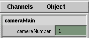
In a view panel, select Panels -> Perspective -> cameraMain.
Now select View -> Select Camera. Now you have this
camera's attributes in the channel box. The one attribute that is
keyable is the cameraNumber attribute.
By changing cameraNumber you change what camera
cameraMain will look through. If cameraNumber is 2, then
cameraMain will look through camera2.
Note: When you first change the cameraNumber, cameraMain will not look through the chosen camera. You must playback
the scene, or change your current frame for cameraMain to pop
to its new position.
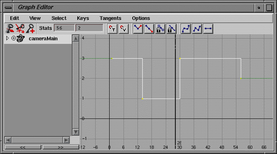
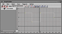
STEP THREE
You now want to set keys
on cameraNumber so that
you can animate the
cutting of the camera.
From the Animation
preferences Under the
Keys section, set the
Click to view a larger version
Default Out Tangent to
Stepped. This will make sure that you jump from camera to
camera at each key.
To set keys on cameraNumber, select the cameraNumber
attribute in the channel box then select Channels -> Key
selected. The robot scene starts with camera3, switches to
camera1, back to camera3 then finally to camera2.
Once the keys are set, you can preview the cuts by playing
http://www.aw.sgi.com/assistant_online/entertain/maya/how_tos/rendering/camera_cuts/ (2 of 3) [3/7/2000 14:42:30]


Assistant Online - Maya/How Tos/Rendering/Camera Cuts
back the scene using cameraMain. To control the timing of
when the cuts occur, you can now easily change the timing of
the keys using the graph editor.
CONCLUSION
When you are happy with the results, you can render out the
scene by making cameraMain as the renderable camera. Don't
forget to turn off the renderable attribute for the perspective
camera.
Note: If you are using motion blur, rendering out the cuts using
cameraMain will create an exaggerated blur at the first frame
of every cut. For instance, as the camera cuts from camera1 to
camera2, there will be a lot of motion blur as the camera leaps
to the new position.
If you want to use motion blur, you can either delete these
incorrect frames, or you can use the cameraMain to find out
where the cuts should occur then use the actual cameras
( camera1, camera2 etc.) to render. To make sure that each
camera renders out with the same name, use a File Name
Prefix in the Render Globals Window.
Use of this file confirms your agreement to the Terms and Conditions
set out on the Terms and Conditions page.
http://www.aw.sgi.com/assistant_online/entertain/maya/how_tos/rendering/camera_cuts/ (3 of 3) [3/7/2000 14:42:30]


Assistant Online - Maya/How Tos/Rendering/Create Camera
Alias|Wavefront / Assistant Online / Maya / How Tos / Rendering / Create Camera
HOW TO CREATE A CAMERA CUT
by Robert Magee
CAMERA
Maya Complete
Rendering
This lesson teaches how to create the cameraMain.ma
camera. In this lesson, you will learn how to set up a camera
that will use an expression to cut between other cameras in the
scene. This expression uses a new attribute called
cameraNumber to decide which other camera in the scene to
"mimic." Basically cameraMain takes on all the key attributes of the chosen camera.
This camera is designed to be used in the How to animate
camera cuts lesson.
STEP ONE
Select Create -> Camera.
Rename this camera cameraMain. This is very important
since the expression you will be writing refers to this camera
name.
STEP TWO
With the Camera selected, select Modify -> Add Attribute...
Set the following:
● Attribute name to cameraNumber.
Data Type
●
to Integer
Click OK.
This new Attribute will be used to determine which camera,
cameraMain will be mimicking. Its name is very important
since the expression uses this attribute name.
http://www.aw.sgi.com/assistant_online/entertain/maya/how_tos/rendering/camera_cuts/camera.html (1 of 2) [3/7/2000 14:42:52]


Assistant Online - Maya/How Tos/Rendering/Create Camera
STEP THREE
With the Camera selected, select Window -> Expression
Editor.
Create this expression. To understand how the expression works, read the script's comments.
CONCLUSION
When using this camera, it is important that your other
cameras are named camera1, camera2 etc. To switch
between them, you can now set keys on the cameraNumber
attribute.
For more details on how to use this camera, complete the
How to animate camera cuts lesson.
Use of this file confirms your agreement to the Terms and Conditions
set out on the Terms and Conditions page.
http://www.aw.sgi.com/assistant_online/entertain/maya/how_tos/rendering/camera_cuts/camera.html (2 of 2) [3/7/2000 14:42:52]
http://www.aw.sgi.com/assistant_online/entertain/maya/how_tos/rendering/camera_cuts/img/cut4_lg.gif http://www.aw.sgi.com/assistant_online/entertain/maya/how_tos/rendering/camera_cuts/img/cut4_lg.gif [3/7/2000 14:43:01]


Assistant Online - Maya/How Tos/Rendering/Clouds
Alias|Wavefront / Assistant Online / Maya / How Tos / Rendering / Clouds
HOW TO MAKE
by Tom Kluyskens
NATURAL CLOUDS
Maya Complete
Rendering
In this lesson you
will learn how to
create fly-through,
shadowable clouds.
To achieve this
result, you will
create a shading
network using the
sampler info node, a
reverse utility node
and a ramp texture.
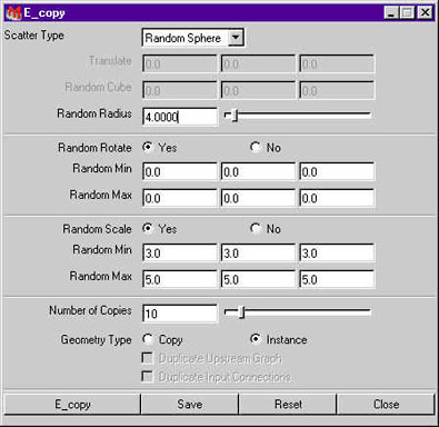
STEP ONE
Create a sphere.
Use the E_copy script to randomize some copies of the sphere.
Use the settings as shown below.
If you are unfamiliar with the use of mel scripts, please see How
to use an Assistant_Online Script
http://www.aw.sgi.com/assistant_online/entertain/maya/how_tos/rendering/clouds/ (1 of 6) [3/7/2000 14:43:10]


Assistant Online - Maya/How Tos/Rendering/Clouds
STEP TWO
Delete the original sphere.
The result should look like
this.
Select all spheres and
disable their double sided
option in the Window ->
Rendering Editors ->
Rendering Flags. This will make them more transparent,
especially at the borders.
Important : The spheres must have a high degree of overlap or
the spheres will be visible. They must NOT be scaled too much
along one axis or you will see artifacts.
Also note that too many spheres will slow down the render time.
Use a maximum of 10.
http://www.aw.sgi.com/assistant_online/entertain/maya/how_tos/rendering/clouds/ (2 of 6) [3/7/2000 14:43:10]
Assistant Online - Maya/How Tos/Rendering/Clouds
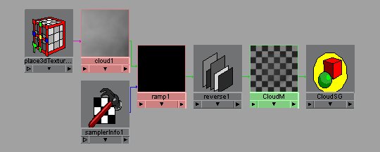
STEP THREE
Create a Lambert shading group, a ramp texture (without
texture placement), a cloud texture, a sampler info utility and a
reverse utility.
Assign the Lambert shading group to the spheres. Rename the
LambertSG to CloudSG, and the Lambert material to CloudM.
Drag the MMB with the cloud texture onto the ambient color of
the CloudM material node.
Scale the Cloud place3Dtexture to 4,4,4.
http://www.aw.sgi.com/assistant_online/entertain/maya/how_tos/rendering/clouds/ (3 of 6) [3/7/2000 14:43:11]
Assistant Online - Maya/How Tos/Rendering/Clouds
STEP FOUR
Connect as follows,
using the Hypershade.
Connect the
●
outColor of the
ramp to the input
of the reverse
node.
Connect the
●
reverse output to
the transparency
of the CloudM
node. We reverse
the cloud color,
because we want
the clouds
transparent where
they are colored
black.
Connect the
●
sampler info
facing ratio to the
U Coord of the
ramp
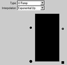
Set the type of the
●
ramp to URamp
and change the
interpolation to
exponential up.
Map the Cloud to
the top tab and
configure as
indicated. (bottom
tab just black).
The Ramp, using
●
the sampler info
facing ratio as an
Input, will modify
the Cloud so that
the borders of the
spheres will be
transparent (black
becomes white
through the
reverse utility
node, thus totally
http://www.aw.sgi.com/assistant_online/entertain/maya/how_tos/rendering/clouds/ (4 of 6) [3/7/2000 14:43:11]


Assistant Online - Maya/How Tos/Rendering/Clouds
transparent). If the
U Coord
(connected to the
Facing Ratio in
this example) of a
U Type Ramp is 0,
the output color
will be the bottom
color of the ramp,
if it's 1, the top of
the ramp is the
output color.
Note: The Facing Ratio is the degree to which a point on a surface is facing towards the camera. If the point is located on a part of the surface that is facing 90 degrees away from the camera (typically the border of a
sphere), the Facing Ratio is 0. If the angle between the surface normal
and the camera ray is 0, the Facing Ratio is 1.
STEP FIVE
Put some lights in the scene :
1 directional for the sunlight
●
1 ambient (with a bit of ambient shade) for the scattered
●
light
Some colored Point lights with decay, placed inside the
●
clouds to give the clouds some local color (if you want or
need them).
http://www.aw.sgi.com/assistant_online/entertain/maya/how_tos/rendering/clouds/ (5 of 6) [3/7/2000 14:43:11]


Assistant Online - Maya/How Tos/Rendering/Clouds
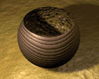
CONCLUSION
You have now
created a shading
network that
produces some
interesting
transparent cloud
effects.
With this shader,
you can also try
scaling or animating
the 3D placement texture node, or adjusting attributes on the
CloudM material node for different effects.
Here is the completed cloud scene, cloud.ma (106k)
E_copy script was written by Gyedo
Jeon
Your use of this file confirms your agreement to the
Terms and Conditions set out in the Terms and Conditions page.
http://www.aw.sgi.com/assistant_online/entertain/maya/how_tos/rendering/clouds/ (6 of 6) [3/7/2000 14:43:11]
http://www.aw.sgi.com/assistant_online/entertain/maya/how_tos/rendering/clouds/img/cloudhg.jpg http://www.aw.sgi.com/assistant_online/entertain/maya/how_tos/rendering/clouds/img/cloudhg.jpg [3/7/2000 14:43:18]


Assistant Online - Maya/How Tos/Rendering/Depth of Field
Alias|Wavefront / Assistant Online / Maya / How Tos / Rendering / Depth of Field
HOW TO USE DEPTH OF FIELD
by Steve Christov
Maya Complete
Rendering
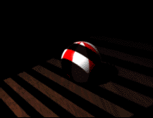
This tutorial will teach you
how to use Depth of Field in
Maya to help add some
realism of your renderings
and animations.
You will be using the
measure tool to determine
the distance from the camera to your object and then adjusting
depth of field attributes such as F-stop and Focus Scale.
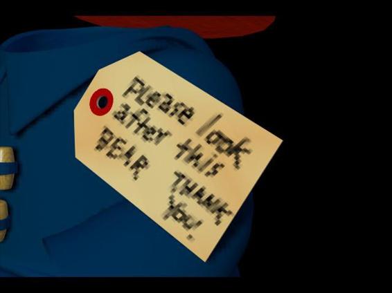
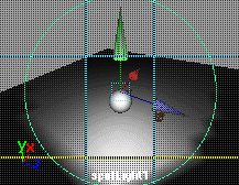
STEP ONE
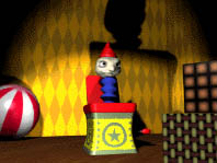
Open your completed Jack in the box tutorial from Learning
Maya.
Create a new camera. With the camera selected open the
Attribute Editor, click on the cameraShape tab.
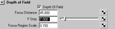
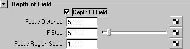
Open the Depth of Field section. Set Depth of Field to On.
http://www.aw.sgi.com/assistant_online/entertain/maya/how_tos/rendering/depth_field/ (1 of 3) [3/7/2000 14:43:49]


Assistant Online - Maya/How Tos/Rendering/Depth of Field
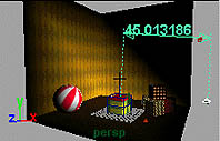
STEP TWO
To establish what your depth
of field is going to focus on,
you will need to measure the
distance from your camera to
the object or area you
focusing on.
Go to Modify > Measure > Distance Tool, and use the four view panels to measure the distance from camera1 to the Jack.
Reselect the new camera. In the Depth of Field section, set
Focus Distance to the value determined by the measure
distance tool.
Render your scene in the render view window.
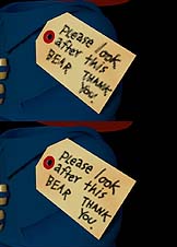
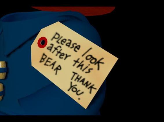
STEP THREE
You will notice that the
desired effect of a focused
Jack and unfocused
foreground and background
elements is minimal in this
rendering. This is because
the present units in the
scene are measured in
centimeters which makes the model too small to make use of
any normal F-stop setting.
Try to imagine photographing the toys on your desk with a
camera standing only a foot away. You would not see the effect
of depth of field because the objects are too small. Fortunately
you have the option to scale the camera down to achieve a
realistic result in these units.
In the camera attribute change the Focus Region Scale to
around 0.15. This is an approximate conversion from
centimeters to feet. Now the camera's F-stop will acts as if Jack
is a little further away.
Re-render your scene. You should now see the Jack in the box
in focus while the objects around it are slightly blurred.
http://www.aw.sgi.com/assistant_online/entertain/maya/how_tos/rendering/depth_field/ (2 of 3) [3/7/2000 14:43:49]


Assistant Online - Maya/How Tos/Rendering/Depth of Field
STEP FOUR
To change the range of distances in which the objects appear
in sharp focus you can use the F-stop. Increase the F-stop to
around 7.00 to create a longer depth of field. Aim for a result
that has the entire Jack in the Box in focus while the objects
around it are blurred.
CONCLUSION
Using Depth of Field, you can add a little realism to your
renderings. As you animate your cameras, this effect will be
even more visible.
TIP: To make the camera automatically focus on its center of
interest (similar to a real-world camera's auto-focus function),
connect the output of the camera group node's Distance
Between attribute to the input of the camera shape node's
Focus Distance attribute. This is only possible with two-node
and three-node cameras because one-node cameras do not
have a camera group node.
Download a finished scene file:
Jack_Depth.ma[~372kb]
Your use of this file confirms your agreement to the
Terms and Conditions set out in the Terms and Conditions page.
http://www.aw.sgi.com/assistant_online/entertain/maya/how_tos/rendering/depth_field/ (3 of 3) [3/7/2000 14:43:49]


Assistant Online - Maya/How Tos/Rendering/Double Sided Shader
Alias|Wavefront / Assistant Online / Maya / How Tos / Rendering / Double Sided Shader
HOW TO CREATE A DOUBLE-SIDED
by Robert Magee
SHADER
Maya Complete
Rendering
In this lesson, you will learn
how to create a two-sided
shading group where you
have one material node on
one side and a different
material node on the other.
This workflow is similar to
the instructions found in the
What's new in Maya 2.0
guide except that rather than using different textures which
share a material node, this example uses different material
nodes that share a shading group node. This allows you to
easily add various texture maps to the two materials, enhancing
the look of both sides of the surface.
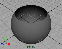
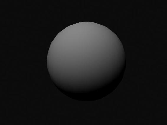
STEP ONE
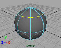
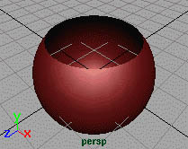
Select Create > NURBS
Primitives > Sphere.
Hit 3 on the keyboard to
increase the sphere
smoothness.
Click on the sphere with
your right mouse button
and select Isoparm from
the marking menu. Select an isoparm near the top of the
sphere. It will highlight in yellow.
http://www.aw.sgi.com/assistant_online/entertain/maya/how_tos/rendering/double_sided/ (1 of 5) [3/7/2000 14:45:15]


Assistant Online - Maya/How Tos/Rendering/Double Sided Shader
STEP TWO
Select Edit Surfaces >
Detach Surfaces. This
breaks the sphere along
the selected isoparm.
Select the top surface and
delete it. Now you have a
sphere where you can
clearly see the inside and
the outside. You will use this surface to test your double sided
shading group.
STEP THREE
Open the Hypershade.
Select Create > Create
Render Node. Under the
Materials tab choose a
Blinn material. Make sure
with shading group is
checked.
Using the Attribute Editor
Change the color of the Blinn material to a red then Assign the shading group to the sphere. The color will help you distinguish
it from the inside material later.
STEP FOUR
From the Hypershade, select Create > Create Render Node and choose the following:
Materials:
• a Phong material With Shading Group turned Off.
Utilities:
• Condition
• Sampler Info
The Phong will be used for the second surface while the utility
nodes will be used to build the two-sided nature of the shading
group.
http://www.aw.sgi.com/assistant_online/entertain/maya/how_tos/rendering/double_sided/ (2 of 5) [3/7/2000 14:45:15]


Assistant Online - Maya/How Tos/Rendering/Double Sided Shader
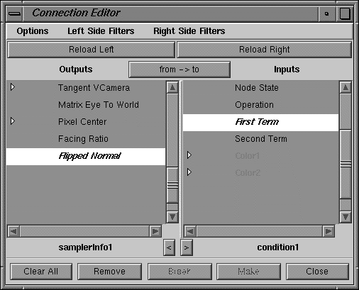
STEP FIVE
With your middle mouse
button, drag the
samplerInfo node onto the
condition node. This will
open the Connection
Editor.
Connect the samplerInfo
node's flipped Normal
attribute to the condition
Click here to view larger image
node's First Term
attribute.
This will establish the surface normal as the driver of the
condition. When the renderer sees a point on the inside of the
surface, the samplerInfo node will tell it that there is a flipped normal and the condition node will know to change the
material.
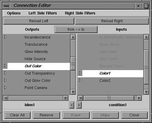
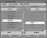
STEP SIX
With your middle mouse
button drag the blinn node
onto the condition node.
Connect the blinn node's
Out Color to the condition
node's Color1.
This establishes the blinn
material as one side of the
Click here to view larger image
shading group.
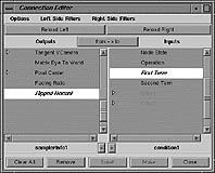
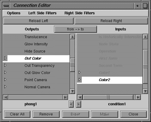
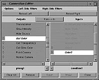
STEP SEVEN
With your middle mouse
button drag the phong node
onto the condition node.
Connect the phong node's
Out Color to the condition
node's Color2.
This establishes the phong
material as the second side
Click here to view larger image
of the shading group. Leave
the Connection Editor open for the next step.
http://www.aw.sgi.com/assistant_online/entertain/maya/how_tos/rendering/double_sided/ (3 of 5) [3/7/2000 14:45:15]


Assistant Online - Maya/How Tos/Rendering/Double Sided Shader
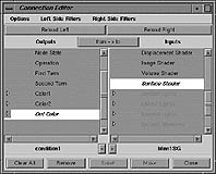
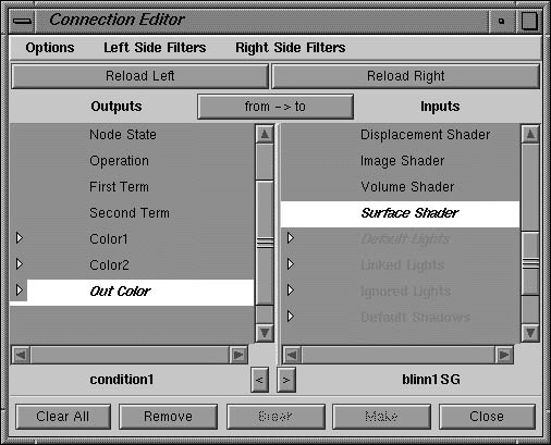
STEP EIGHT
Click the Clear All button in
the Connection Editor.
Delete the connection
between the Blinn1 node
and the BlinnSG node in the
Hypershade.
Select the Blinn node and
click the Show Up and
Click here to view larger image
DownStream Connection to
view the blinn1SG.
Use your middle mouse button to drag the condition node to the
outputs section of the Connection Editor.
With your middle mouse button drag the blinn1SG node to the
Inputs section of the Connection Editor. Connect the condition
node's Out Color attribute to the blinnSG node's Surface Shader attribute.
This allows the underlying network to plug directly into the
Shading Group node. The shader is now ready to be rendered.
Note: If you have hardware texturing turned on you will not see
the shading group displayed properly. You will have to render to
see the results.
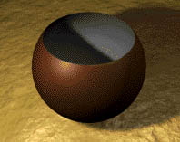
STEP NINE
You can now add lights to
your scene, set up your
Render Globals and render
the scene to see the two
sided surface.
Note: If you want to reverse
which surface is on the
inside and which is on the
outside then open up the condition node in the Attribute editor
and change the Operation from Equal to Not Equal.
http://www.aw.sgi.com/assistant_online/entertain/maya/how_tos/rendering/double_sided/ (4 of 5) [3/7/2000 14:45:15]


Assistant Online - Maya/How Tos/Rendering/Double Sided Shader
STEP TEN
Because you now have two
material nodes feeding the
inside and outside of the
shading group, you can
apply various texture maps
to the different materials.
For instance you could
apply a color map, specular
map and bump map to Blinn material node to give it a look of
wood then apply different maps to the Phong material to create
a bumpy stone pattern.
CONCLUSION
Creating a double-sided shading group that offers different
material qualities on the two sides is a great way of working with
certain kinds of surfaces. Clothing is a good example where you
might want a rough wool fabric on the outside and a shiny silk
lining on the inside.
You can download the shading group from this lesson assign it
to your own objects. You can even use this shading group as a
template and replace the textures to create your own look.
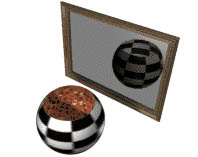
Note: One limitation of
double-sided surfaces is that
the inside surface will not
reflect or refract when
raytraced. The image shown
to the right is a two-sided
surface that is reflected in a
mirror. You can see that the
grainy interior of the sphere is
not reflected in the mirror.
Download shader: double.ma[~4kb]
Use of this file confirms your agreement to the Terms and Conditions
set out on the Terms and Conditions page.
http://www.aw.sgi.com/assistant_online/entertain/maya/how_tos/rendering/double_sided/ (5 of 5) [3/7/2000 14:45:15]
http://www.aw.sgi.com/assistant_online/entertain/maya/how_tos/rendering/double_sided/img/double6_lg.jpg http://www.aw.sgi.com/assistant_online/entertain/maya/how_tos/rendering/double_sided/img/double6_lg.jpg [3/7/2000 14:45:19]
http://www.aw.sgi.com/assistant_online/entertain/maya/how_tos/rendering/double_sided/img/double7_lg.jpg http://www.aw.sgi.com/assistant_online/entertain/maya/how_tos/rendering/double_sided/img/double7_lg.jpg [3/7/2000 14:45:23]
http://www.aw.sgi.com/assistant_online/entertain/maya/how_tos/rendering/double_sided/img/double8_lg.jpg http://www.aw.sgi.com/assistant_online/entertain/maya/how_tos/rendering/double_sided/img/double8_lg.jpg [3/7/2000 14:45:27]
http://www.aw.sgi.com/assistant_online/entertain/maya/how_tos/rendering/double_sided/img/double9_lg.jpg http://www.aw.sgi.com/assistant_online/entertain/maya/how_tos/rendering/double_sided/img/double9_lg.jpg [3/7/2000 14:45:30]


Assistant Online - Maya/How Tos/Rendering/Environment Sky
Alias|Wavefront / Assistant Online / Maya / How Tos / Rendering / Environment Sky
HOW TO CREATE A REALISTIC
By Steve Christov
SKY WITH THE ENVSKY TEXTURE
Maya Complete
Rendering
The environment sky is a
powerful procedural
texture that you can
quickly and easily add to
your scene to give the
appearance of a sky
overhead.
In this first part of a three
part lesson you will learn
Play Movie [~800k]
how to create an
environment sky and set attributes that will create a realistic
looking sky.
In the next lesson - How to create realistic shadows using
envSky - you will learn how to achieve realistic shadows using the position of the sun on the EnvSky texture. In the final lesson
you will learn how to "grow" a tree in Paint Effects from a simple black brush stroke - How to create a tree using Paint Effects.
After these three lessons, you will be able to combine these
elements to produce an animation similar to the one above
where you create a time lapse animation of a sunset.
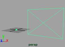
STEP ONE
You will first need to
create a new camera
and then attach an
image plane to it.
Create a new camera by
selecting Create >
Camera.
Translate
●
the
camera 2 units in
the Y axis and 6 in
http://www.aw.sgi.com/assistant_online/entertain/maya/how_tos/rendering/env_sky/ (1 of 7) [3/7/2000 14:45:46]


Assistant Online - Maya/How Tos/Rendering/Environment Sky
the Z axis.
Open the Attribute
●
Editor for the new
camera, and open
the Environment
section. Click on
the Create button
next to Image
Plane. The
Attribute Editor
window will now
switch to the
Attribute Editor for
the Image Plane.
Open the
●
Placement section
and click on Fit to
Resolution Gate.
This will ensure
that your image
plane will fill the
entire rendered
scene.
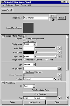
STEP TWO
While you are still in the
Attribute Editor for the
Image Plane, Click on
the Map
button
next to Texture and
map an EnvSky.
The EnvSky node is
located in the
Environment Textures
section of the Create
Render Node window.
http://www.aw.sgi.com/assistant_online/entertain/maya/how_tos/rendering/env_sky/ (2 of 7) [3/7/2000 14:45:46]


Assistant Online - Maya/How Tos/Rendering/Environment Sky
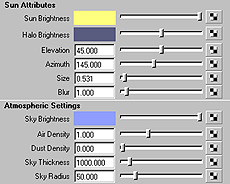
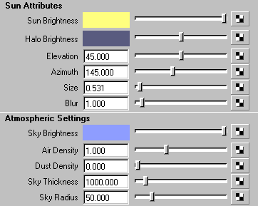
STEP THREE
You will now set the
colors for your
environment. In the
Attribute Editor for the
EnvSky, Set the
following attributes:
Sun Brightness
●
to 1, 1, 0.5
Halo Brightness
●
to 0.35, 0.36, 0.5
Under
●
Atmospheric
Settings, Set the
Sky Brightness to
0.56, 0.617, 1.0
To change any of the color values, select the color icon next to
the attribute. This will open the Color Chooser. Make sure you
are using the RGB values by checking the RGB box near the
bottom of the window. You can then type the values in manually.
NOTE: To open the Attribute Editor for the EnvSky, select the
3D Icon for the EnvSky texture and open the Attribute Editor.
Click the Goto Output Selection Button
at the top right
side. This will take you to the EnvSky Attribute Editor.
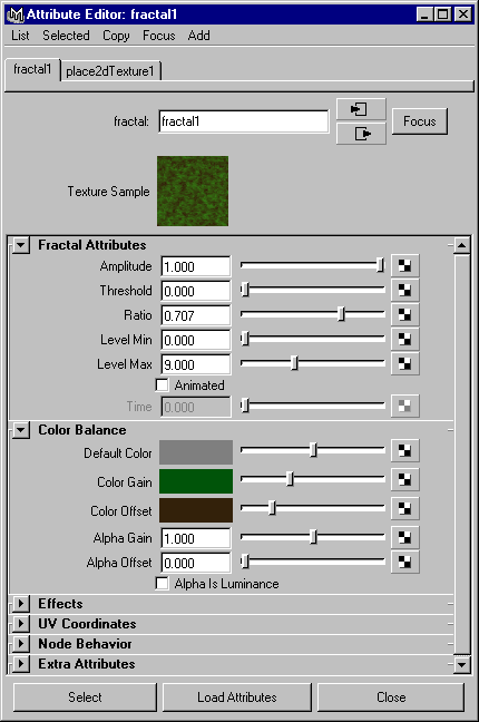
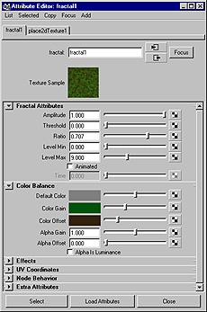
STEP FOUR
Open the Floor
Attributes section for the
EnvSky, Map the color
of the floor to a 2D
Fractal texture.
Change the Color Gain
to a Dark Green and the
Color Offset to a Dark
Brown. This will be your
floor.
Select Camera 1 and
Select > Panels > Look
Through Selected. Turn
on the Resolution Gate
by selecting View >
Camera Settings >
Resolution Gate.
Render this view by
selecting Render > Render into New Window.
http://www.aw.sgi.com/assistant_online/entertain/maya/how_tos/rendering/env_sky/ (3 of 7) [3/7/2000 14:45:46]


Assistant Online - Maya/How Tos/Rendering/Environment Sky
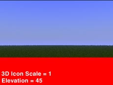
STEP FIVE
When you render with
the floor turned on, you
may encounter a bright
red surface for part of
the floor. This is due to
the fact that your
camera is rendering a
point that is below the
Floor Altitude. You can
fix this by either lowering the Floor Altitude, raising the look at
point of the camera, or scaling the 3D icon. In this case we are
going to scale the icon.
Select the EnvSky icon in the perspective view window. In the Channel Box set the Scale X Y Z to 5.
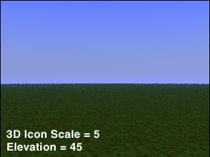
Re-Render your
scene. You should now
have a floor that
extends to a vanishing
point.
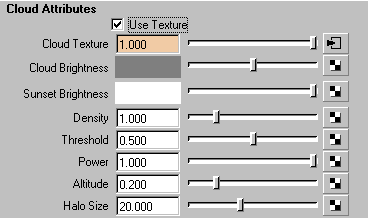
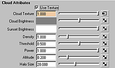
STEP SIX
You are now ready to
add clouds to the
scene. Open the Cloud
Attributes section in the
Attribute Editor for the
EnvSky. Click the box
next to Use Texture to
turn it on.
Click the Map button next to Cloud Texture. This will open the Create Render Node window. Select a Cloud Texture.
http://www.aw.sgi.com/assistant_online/entertain/maya/how_tos/rendering/env_sky/ (4 of 7) [3/7/2000 14:45:46]


Assistant Online - Maya/How Tos/Rendering/Environment Sky
STEP SEVEN
Preview your sky by
rendering the Camera 1
view.
You will notice clouds in
the scene but they are
faint. You can make
them more pronounced
by setting the density.
Set the Density under
the Cloud Attribute of the EnvSky to 2.0.
Render your scene. You
should now see clouds in
the sky.
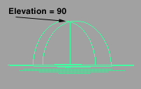
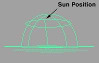
STEP EIGHT
Switch to your persp camera.
If you take a close look at the
3D icon for the EnvSky, you
will notice that there is a point
that represents the sun. By
adjusting the Elevation,
Azimuth and Size, you will change the position and size of this point.
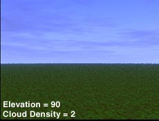
Set the Elevation to 90 degrees. This will position the sun directly in the middle of the sky and also produce the brightest
light. Notice on the 3D icon, that the sun icon has moved directly
to the top middle of your icon.
Render the scene. You
should now see a bright
blue sky.
http://www.aw.sgi.com/assistant_online/entertain/maya/how_tos/rendering/env_sky/ (5 of 7) [3/7/2000 14:45:46]

Assistant Online - Maya/How Tos/Rendering/Environment Sky
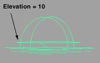
STEP NINE
You will now position the
sun so that it appears in
your scene. To do this you
will need to align the line
that represents the sun to
intersect a point in your
image plane. Make the
following changes to position and size of the sun so that it will
be seen in the image plane.
Elevation
●
to 10
Azimuth
●
to 0
Size
●
to 3.0
If you imagine the line on the
3D icon representing the sun
going off to infinity, it will
intersect the image plane
which in turn will render the
sun in your image. You may
need to switch to your persp
view and zoom out to see this.
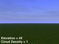
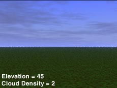
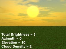
Render the Scene. Notice how the color of the sky changes in relation to the elevation of the sun. At an elevation of 90, you
get an image that has the brightest possible sky. At a lower
elevation your sky begins to change to a darker color.
However the appearance of the sun does not seem quite
bright enough. In this case we will increase the total
brightness to get a nice sunset.
Increase the Total Brightness to 3.0.
Render the Scene. You should now have a decent looking
sunset.
Save your File.
CONCLUSION
You have now setup an
EnvSky texture that will
produce an
environment complete
with sun and clouds.
There are many
attributes to experiment
with on this texture. You
can achieve some
interesting results by adjusting the some of the Atmospheric
and Cloud attributes.
http://www.aw.sgi.com/assistant_online/entertain/maya/how_tos/rendering/env_sky/ (6 of 7) [3/7/2000 14:45:46]


Assistant Online - Maya/How Tos/Rendering/Environment Sky
In the next lesson you will use this file and learn how-to achieve
realistic shadows based on the position of the sun.
Download the completed envSky.ma [~60k]
Go to How to create realistic shadows using envSky.
Use of this file confirms your agreement to the Terms and Conditions
set out on the Terms and Conditions page.
http://www.aw.sgi.com/assistant_online/entertain/maya/how_tos/rendering/env_sky/ (7 of 7) [3/7/2000 14:45:46]


Assistant Online - Maya/How Tos/Rendering/Environment Sky Shadows
Alias|Wavefront / Assistant Online / Maya / How Tos / Rendering / EnvSky_Shadows
HOW TO CREATE REALISTIC
By Steve Christov
SHADOWS WITH ENVSKY
Maya Complete
Rendering
This lesson is a
continuation of How to
In this lesson you will
use your environment
sky texture from the last
lesson and link a
directional light to the
elevation and azimuth that will simulate the shadows cast when
you animate the position of the sun.
In the final lesson you will learn how to "grow" a tree in Paint Effects from a simple black brush stroke - How to create a tree
STEP ONE
Open Env_Sky.ma file that you saved from the last
lesson.
In the Attribute Editor for the
EnvSky, Set the Elevation
and Azimuth to 0. Set the
Total Brightness to 1.0.
Providing you have not moved or rotated the 3D icon the sun
position should be lined up along the Z axis.
http://www.aw.sgi.com/assistant_online/entertain/maya/how_tos/rendering/env_sky_shadow/index.html (1 of 6) [3/7/2000 14:45:57]


Assistant Online - Maya/How Tos/Rendering/Environment Sky Shadows
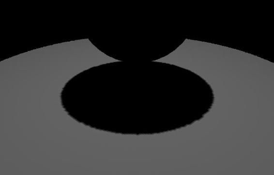
STEP TWO
You are now ready to create
a directional light and link it
into the attributes of the
EnvSky texture.
Create a Directional Light
by selecting Lights ->
Create Directional Light.
You will want this light to cast shadows so you will need to turn
on shadows. Open the Attribute Editor for the light. In the
shadows section, Click the box next to the Use Depth Map
Shadows.
You will notice that the light is pointing at the sun rather than
away from it. Rotate the light 180 in the Y axis. This will align it properly.
STEP THREE
With the light
selected, Group it to itself by selecting Edit > Group.
In the Attribute Editor Rename this node lightLinker.
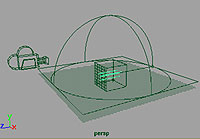
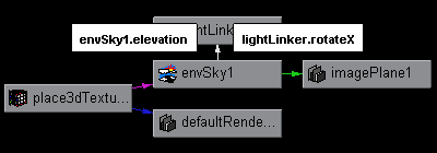
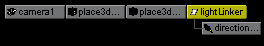
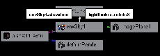
STEP FOUR
Open the Hypergraph
window and holding
the shift key, Select
the lightLinker node
and the place3dTexture node for EnvSky.
Select Graph > Up and Downstream Connections.
With the Middle Mouse Button, Drag the EnvSky1 node onto
the lightLinker node.
In the Connection Window that opens, click on Elevation on
the left side, then click on Rotate X on the right. This connects
the Elevation on the EnvSky node to the Rotate X attributes on
the lightLinker node.
Close the Connection Editor window.
http://www.aw.sgi.com/assistant_online/entertain/maya/how_tos/rendering/env_sky_shadow/index.html (2 of 6) [3/7/2000 14:45:57]


Assistant Online - Maya/How Tos/Rendering/Environment Sky Shadows
STEP FIVE
In the
Hypergraph
window, click
on
Rendering > Create Render Node window.
If you were to directly connect the azimuth to the directional
light you would find that as you adjust the azimuth your light
would rotate in the opposite direction. In this case a reverse
node will be used to correct this.
In the Create Render Node window, click on the Utilities tab.
Under General Utilities section, Create a Reverse node.
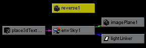
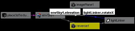
STEP SIX
In the Hypergraph
window, Drag with
the Middle Mouse Button, the EnvSky1 node onto the Reverse
node. This will open the Connection Editor.
Connect the Azimuth on the left side, with the Input X on the right side.
In Hypergraph, Drag the Reverse node onto the lightLinker node. In the Connection Editor, Connect Output X to the
Rotate Y.
Test your light connection by opening the Attribute Editor for
the EnvSky node, and changing the Elevation and Azimuth
settings.
You should now notice that the directional light will rotate along
with the Elevation and Azimuth.
STEP SEVEN
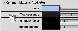
Create a plane, by
selecting Create >
NURBS Primitive >
Plane.
Because you are
unable to cast
shadows on the floor
of the EnvSky, you will
need to turn it off. Open the Attribute Editor and Uncheck the
box next to Has Floor. Scale the Plane out to roughly 35 units.
Create a new Lambert material in the Hypershade, Change the
color of the new Lambert to white. This will make it easier to
see the shadow.
http://www.aw.sgi.com/assistant_online/entertain/maya/how_tos/rendering/env_sky_shadow/index.html (3 of 6) [3/7/2000 14:45:57]


Assistant Online - Maya/How Tos/Rendering/Environment Sky Shadows
Assign this material to the Plane.
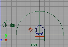
Select Create > NURBS Primitive > Sphere. Move the
sphere up in the Y axis. This will be your shadow casting object
and will make it easier to see where the shadow will fall.
Assign a new material to the sphere. Move the sphere so that
it sits just above the floor.
Select Lights > Create Ambient Light. Move the light to a
point in front of the cone. Set the Intensity to 0.5.
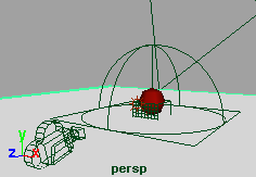
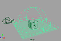
STEP EIGHT
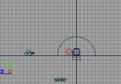
Position Camera1 in
your scene. The most
effective positioning
of the camera when
using an EnvSky is to
point the camera
slightly towards the
sky.
Move the camera away from the cone to see a good portion of
the floor in front of it. This is where your shadow will be cast.
Make sure that the camera is not positioned past the edge of
the plane.
STEP NINE
You are now are going to
animate the clouds.
Select the 3D icon for the
cloud. Move it 6 units in the Z
axis. Set a key at time 1 by
selecting Translate Z in the
channel box and with the right
mouse button select Key
Selected from the drop down
menu. Set another key for the Rotate X attribute value at
time 1.
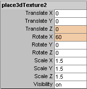
Move the time slider to time 100. Change the Translate Z of
the icon to 0 and set a key. Change the Rotate X to 60 and set another key.
http://www.aw.sgi.com/assistant_online/entertain/maya/how_tos/rendering/env_sky_shadow/index.html (4 of 6) [3/7/2000 14:45:57]


Assistant Online - Maya/How Tos/Rendering/Environment Sky Shadows
STEP TEN
You are now ready to
animate the setting of
the sun.
Move your time slider
to 1. Set the elevation
attribute on the
EnvSky to 75 and click
the attribute with your
right mouse button and select Set Key.
Change the time slider to 100. Change the elevation to 0 and Set a Key.
Press Play, you should now see the EnvSky icon animate the
elevation over time.
Set up your Render Globals to render out 100 frames from
Camera1. Save your file and then render out the frames.
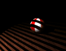
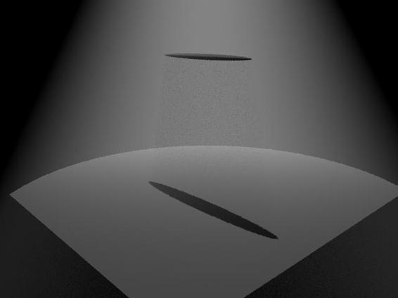
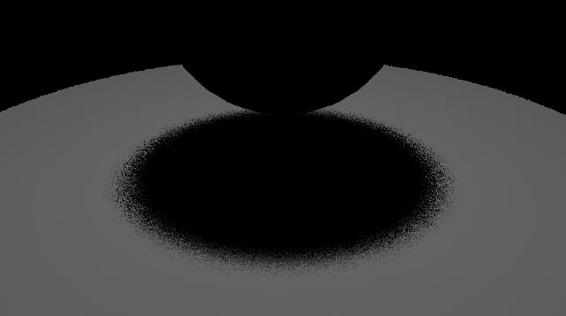
CONCLUSION
You have now
constructed an EnvSky
that will cast accurate
shadows according to
the position of the sun.
Click on the image to
get a "time lapse"
animation of a setting
sun. Pay attention to
the length and direction
of the shadow as the
sun sets.
You can further enhance the animation by keying the size and
total brightness of your sun as it sets to produce a more
dramatic sunset. You may also want to key the ambient light
slowly to zero intensity at around frame 80 so that your objects
fade completely to black.
In the next lesson you are going to replace the primitive sphere
with a black stroke painted onto the plane and adjust attributes
in Paint Effects until you produce a tree similar to the one
above. You will then assemble all the elements to produce an
animation like the one above.
Go to - How to create a tree using Paint Effects.
Use of this file confirms your agreement to the Terms and Conditions
set out on the Terms and Conditions page.
http://www.aw.sgi.com/assistant_online/entertain/maya/how_tos/rendering/env_sky_shadow/index.html (5 of 6) [3/7/2000 14:45:57]


Assistant Online - Maya/How Tos/Rendering/Environment Sky Shadows
http://www.aw.sgi.com/assistant_online/entertain/maya/how_tos/rendering/env_sky_shadow/index.html (6 of 6) [3/7/2000 14:45:57]
http://www.aw.sgi.com/assistant_online/entertain/maya/how_tos/rendering/env_sky_shadow/img/six_lrg.gif http://www.aw.sgi.com/assistant_online/entertain/maya/how_tos/rendering/env_sky_shadow/img/six_lrg.gif [3/7/2000 14:46:21]
http://www.aw.sgi.com/assistant_online/entertain/maya/how_tos/rendering/env_sky_shadow/img/six_a.gif http://www.aw.sgi.com/assistant_online/entertain/maya/how_tos/rendering/env_sky_shadow/img/six_a.gif [3/7/2000 14:46:24]
http://www.aw.sgi.com/assistant_online/entertain/maya/how_tos/rendering/env_sky/img/three_lrg.gif http://www.aw.sgi.com/assistant_online/entertain/maya/how_tos/rendering/env_sky/img/three_lrg.gif [3/7/2000 14:46:28]
http://www.aw.sgi.com/assistant_online/entertain/maya/how_tos/rendering/env_sky/img/four_lrg.gif http://www.aw.sgi.com/assistant_online/entertain/maya/how_tos/rendering/env_sky/img/four_lrg.gif [3/7/2000 14:46:32]
http://www.aw.sgi.com/assistant_online/entertain/maya/how_tos/rendering/env_sky/img/six_lrg.gif http://www.aw.sgi.com/assistant_online/entertain/maya/how_tos/rendering/env_sky/img/six_lrg.gif [3/7/2000 14:46:34]


Assistant Online - Maya/How Tos/Rendering/Ghost Shader
Alias|Wavefront / Assistant Online / Maya / How Tos / Rendering / Ghost Shader
HOW TO CREATE A GHOST SHADER
by Terry Stoeger
Maya Complete
Rendering
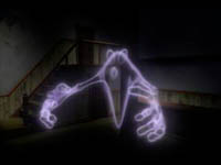
In this lesson, you will learn
how to create a shading
network that has a soft,
fuzzy look.
You will be using the
SamplerInfo utility node and
a Ramp texture to achieve a
transparent drop-off effect.
Play Movie {433 k}
STEP ONE
Select Window -> Hypershade to open it.
Create the following nodes:
Lambert
●
Surface Material (With Shading Group turned
on)
SamplerInfo
●
utility node
Ramp
●
texture (With New Texure Placement turned off)
STEP TWO
You will be connecting the Facing Ratio attribute of the
samplerInfo to the V Coord of the Ramp. The Facing Ratio produces a value that ranges between 0 and 1 depending on
the normal of the surface to the camera eye (normal facing
Camera Eye = 1; perpendicular to Camera Eye = 0).
In the Hypershade, Drag and Drop with MMB samplerInfo onto
the ramp texture. This will open the Connection Editor with the
samplerInfo in the Outputs column and the ramp texture in the inputs column.
Expand the UV Coord in the Inputs column. Click on the Facing
Ratio attribute in the Outputs column and then click on V Coord.
This Connects the samplerInfo's FacingRatio to the Ramp's V
Coord. Close the connection editor.
http://www.aw.sgi.com/assistant_online/entertain/maya/how_tos/rendering/ghost_shader/ (1 of 3) [3/7/2000 14:46:47]


Assistant Online - Maya/How Tos/Rendering/Ghost Shader
STEP THREE
Double click on the Lambert Shading Group to open the
Attribute Editor.
Change the Color to a light gray, green, or blue for the ghost's
color.
You will now map the ramp to the transparency. Drag and
Drop with MMB the ramp texture to the Transparency slider of the Lambert Shading Group.
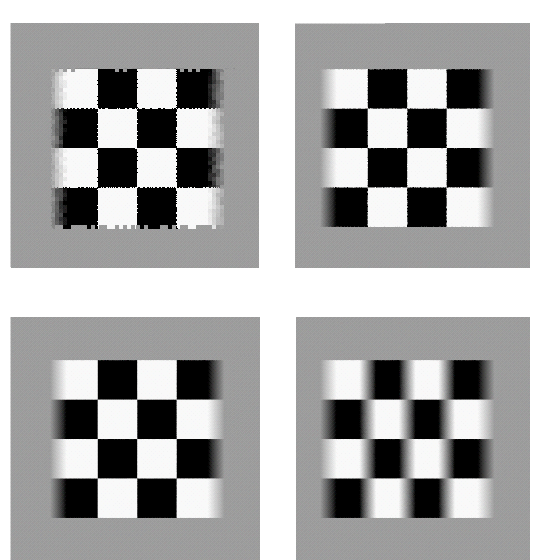
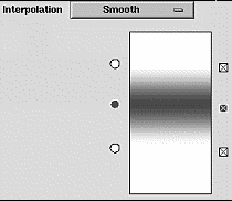
STEP FOUR
Double click on the Ramp
Texture to open the
Attribute Editor.
Change the ramp colors to
a dark grey and white as
show in this figure. Also
change the Interpolation
to Smooth.
For a more ghostly result,
make the material node's Incandescence a dark blue and add
a glow by opening the Special Effects section and increasing
the Glow to .6.
Do a test render and experiment with different ramp settings.
CONCLUSION
You have now constructed
a Shading Network that
creates some interesting
transparent effects. This
technique could also be
used for other attributes
(Incandescence, Specular
Color, Diffusion, etc...).
The ramp colors could
Play Movie {433 k}
also be mapped with a
Fractal or a file texture
http://www.aw.sgi.com/assistant_online/entertain/maya/how_tos/rendering/ghost_shader/ (2 of 3) [3/7/2000 14:46:47]


Assistant Online - Maya/How Tos/Rendering/Ghost Shader
(image) for a broken, cloudy effect. Try changing the colors for
a different look. This works well for glass (like a jelly jar).
Shift-Click to download the finished ghost shader.
Use of this file confirms your agreement to the Terms and Conditions
set out on the Terms and Conditions page.
http://www.aw.sgi.com/assistant_online/entertain/maya/how_tos/rendering/ghost_shader/ (3 of 3) [3/7/2000 14:46:47]


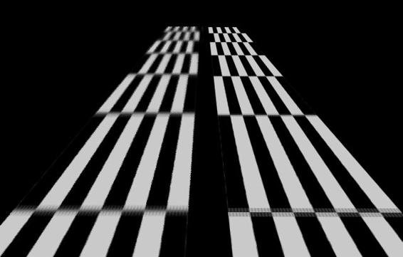
Assistant Online - Maya/How Tos/Rendering/Gobo
Alias|Wavefront / Assistant Online / Maya / How Tos / Rendering / Gobo
HOW TO CREATE A LIGHT
by Robert Magee
GOBO WITH BARN DOORS
MAYA Complete
Rendering
In this lesson, you will
learn how to simulate the
shadow coming from a
window with blinds using
a light gobo.
You will create the blinds
by texture mapping the
color of your spotlight,
then you will set up the
spotlight's barn doors to
complete the effect.
STEP ONE
Create a spotlight. Use
the Show Manipulator
tool to reposition the light
so that it is looking down
at your scene.
In the Attribute editor,
change the light's Cone
Angle to 80.
http://www.aw.sgi.com/assistant_online/entertain/maya/how_tos/rendering/light_blinds/ (1 of 3) [3/7/2000 14:47:12]


Assistant Online - Maya/How Tos/Rendering/Gobo
STEP TWO
In the Attribute editor,
click on the Map button
next to Color. Choose a
grid texture. This texture
will act as the gobo which
will render the window
blind effect.
Change the Grid's U
Width to 0 and it's V Width to 0.5.
Click on the place2DTexture tab and change the Repeat V to
16. Now you have more blinds.
Test render your scene to see how the gobo is working. The
blinds are working fine but the shape of the window needs to be
more rectangular. You will need to set up the spotlight's barn
doors.
STEP THREE
In the Attribute editor,
click on the
spotLightShape node and
go to the Light Effects
section. Turn Barn Doors
to On.
With the light selected,
select Panels -> Look
through selected. You are now looking through the spotlight.
This will make it easier to preview the barn doors.
Select the Show Manipulator tool. Now barn door
manipulators are available in the view. Click drag on them to
set up the shape of your window. You may need to increase
your light's view angle to set up the shape you want. This
example used a View angle of 100.
STEP FOUR
Test render the scene.
Now the window has a
rectangular shape.
If you want to animate
the blinds opening and
closing then you can set
keys on the grid
texture's V width.
Animate it from a value of 1.0 to 0.25.
http://www.aw.sgi.com/assistant_online/entertain/maya/how_tos/rendering/light_blinds/ (2 of 3) [3/7/2000 14:47:12]


Assistant Online - Maya/How Tos/Rendering/Gobo
CONCLUSION
You can combine barn doors and a texture mapped light to
create a number of gobo effects. The shadow from the
leaves of a tree, as well as other effects, can be easily
simulated using a similar technique.
Your use of this file confirms your agreement to the
Terms and Conditions set out in the Terms and Conditions page.
http://www.aw.sgi.com/assistant_online/entertain/maya/how_tos/rendering/light_blinds/ (3 of 3) [3/7/2000 14:47:12]


Assistant Online - Maya/How Tos/Rendering/Aliasing Overview
Alias|Wavefront / Assistant Online / Maya / How Tos / Rendering / Aliasing Overview
ALIASING ARTIFACTS IN MAYA:
by Andrew Woo
A TECHNICAL OVERVIEW
This document describes some of
the key issues to be addressed
which affect the quality of an
image's aliasing when rendering in
Maya.
You will learn how to look for
some of the causes of aliasing
then address these issues while
maintaining good aliasing and
faster rendering times.
The Maya renderer offers many
attributes to help you solve
aliasing problems on a project by
project basis. This technical overview discusses several ways
you can efficiently improve image quality when rendering.
This document is a PDF file and can be viewed/printed using
Adobe Acrobat Reader.
Your use of this file confirms your agreement to the
Terms and Conditions set out in the Terms and Conditions page.
http://www.aw.sgi.com/assistant_online/entertain/maya/how_tos/rendering/overview_aliasing/ [3/7/2000 14:47:20]
images by Chris Beaumont
Aliasing Artifacts in Maya:
A Technical Overview
Maya 1.0.1 IRIX and Maya 1.0 NT
By Andrew Woo
Alias|Wavefront
a Silicon Graphics Company
AP-M-AA-01
Aliasing Artifacts in Maya: A Technical Overview
Algorithms: Maya Rendering Version 1.0, March 1998
ã September 1998, Alias|Wavefront, a division of Silicon Graphics Limited.
Printed in U S A, All rights reserved.
Assist Publishing Group:
Robert Magee, Tracy Barber
Maya 1.0 Rendering Team:
Sanjay Bakshi, Silviu Borac, Josh Cameron, Jim Craighead, Renaud Dumeur, Antoine Galbrun, Philippe Limantour, Ryan Meredith, Chris Patmore, Andrew Pearce, Joe Spampinato, Kelvin Sung, Chris Thorne, Mamoudou Traore, Greg Veres, Gianluca Vezzadini, Changyaw Wang, Andrew Woo.
A document by Andrew Woo
Cover image credit: Chris Beaumont
The following are trademarks of Alias|Wavefront, a division of Silicon Graphics Limited: AliasÔ
MELÔ
Alias PowerTracerÔ
Alias RayTracingÔ
MayaÔ
Alias MetamorphÔ
Alias QuickRenderÔ
Alias SDLÔ
Maya ArtisanÔ
OpenAliasÔ
Alias QuickShadeÔ
Alias ShapeShifterÔ
Maya F/XÔ
Alias OpenModelÔ
Alias QuickWireÔ
Alias StudioPaintÔ
Maya PowerModelerÔ
Alias OpenRenderÔ
Alias RayCastingÔ
ZaPiT!Ô
The following are trademarks of Alias|Wavefront, Inc.:
Advanced VisualizerÔ
ExploreÔ
MediaStudioÔ
3DesignÔ
Wavefront ComposerÔ
Wavefront IPRÔ
MultiFlipÔ
DynamationÔ
KinemationÔ
VizPaint2DÔ
Graph Layout Toolkit Copyright ã 1992-1996 Tom Sawyer Software, Berkeley, California, All Rights Reserved.
All other product names mentioned are trademarks or registered trademarks of their respective holders.
Any forward looking statements in this document are speculative and are based on current assumptions and in no way imply Alias|Wavefront will at any future time act upon said statements. This document contains proprietary and conÞdential information of Alias|Wavefront, a division of Silicon Graphics Limited, and is protected by Federal copyright law. The contents of this document may not be disclosed to third parties, translated, copied, or duplicated in any form, in whole or in part, without the express written permission of Alias|Wavefront, a division of Silicon Graphics Limited.
The information contained in this document is subject to change without notice. Neither Alias|Wavefront, a division of Silicon Graphics Limited, nor its employees shall be responsible for incidental or consequential damages resulting from the use of this material or liable for technical or editorial omissions made herein.
A l i a s | Wav e f r o n t ❚ 210 King Street East ❚ Toronto, Canada M5A 1J7
Aliasing Artifacts
When rendering in Maya, the quality of an imageÕs aliasing is one of
the key issues that must be addressed. Aliasing artifacts can impact
the look of an image and create unsatisfactory results.
One method of dealing with these artifacts is to increase the Shading
samples in MayaÕs Render Globals. While this may solve the aliasing problem, it is often not the most efficient way for the Maya renderer
to deal with the aliasing artifacts. This means that renderings take
longer when in fact it may have been possible to solve the problem
another way.
As well, if you find that the problem can be fixed using another
method which does not require increased shading samples, it is very
easy to forget to reset the original anti-aliasing values. Thus, the
Maya renderer will continue to run a lot slower than needed.
This paper has been written to help you identify and classify typical
aliasing artifacts, with some understanding of the technical
algorithms, so that you can optimally solve these artifacts with
minimal impact to the performance of the renderer. This document
will also help you recognize those cases where eventually the
shading samples will need to be increased.
It can be argued that all the aliasing artifacts should be taken care of
automatically, without much user intervention. Our experience has
found that automatic solutions may limit what you can achieve and
prevent you from finding the desired balance between quality and
performance. The Maya renderer therefore offers many attributes to
help you solve the aliasing problems on an project by project basis.
These attributes ensure that you do not hit a wall when a certain
image quality is desired, or when a certain performance limit needs
to be satisfied. Better automated solutions will be sought through
continued research.
THE CAUSES OF ALIASING
Following is a series of the most common aliasing artifacts, with
visual examples so that you can easily identify the type of artifacts
for future references.
Technical Overview
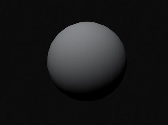
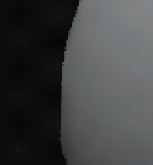
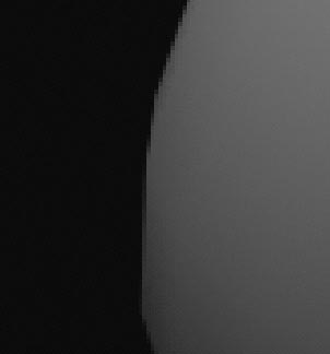
Introduction
Edge Aliasing
Edge Aliasing
The Maya renderer employs a 32-bit, A-buffer to anti-alias polygon edges.
This provides an analytic solution for producing very high quality edge
anti-aliasing results. Thus edge anti-aliasing is separated from shading
anti-aliasing, which also buys some performance gains, because usually a
lot less shading samples are required for good overall anti-aliasing.
Once you identify that the problem is that of edge aliasing, you can go to Render Globals ® Render Quality ® Edge Anti-aliasing to set the attribute to either High Quality or Highest Quality. The following image shows two sphere images that show high and low quality edge aliasing.
Poor quality aliasing
Good quality aliasing
High and low quality edge aliasing
Since it is difficult to see the jagged effects well, the images are resized to show the aliasing more closely.
Poor quality aliasing
Good quality aliasing
Close-up of high and low quality edge aliasing
Thin Geometry Aliasing:
In cases of very thin pieces of geometry, the 32-bit mask for edge anti-
aliasing may not be adequate. This usually occurs when the polygons
themselves are less than one tenth of a pixel wide. Under such situations, the problem gets worse as you see flicker over an animation. Therefore a
multi-resolution bit mask will be implemented in Maya 1.5 IRIX and Maya
2.0 NT to help deal with thin geometry.
2 Aliasing Artifacts in Maya
The Causes of Aliasing
Aliased Edges Through Transparency
Aliased Edges Through Transparency
The 32-bit, A-buffer mask only applies to the first visible fragments in a pixel. If there are surfaces behind a transparent surface, the mask does not apply, and the renderer needs to resort to point sampling. Thus the
Shading samples attribute for that surface needs to be increased to improve both the shading and the edge anti-aliasing of those surfaces.
Unfortunately, the same limitation exists for raytracing.
Specular Highlight Aliasing
The material used for rendering is also a very important consideration.
The more common (isotropic) materials used by our customers include:
■
Phong
■
PhongE
■
Blinn (based on the Torrance-Sparrow model)
Note:
It is mathematically provable that the highlight hotspots for the above materials all sit in the same spot. So the main difference between those
models are how their highlights decay.
The following image has 3 thin cylinders with materials, from top to
bottom, Phong, Blinn + PhongE (with diffuse set to 0). It is important to
note that the Phong model results in a very sharp, hard edge for its
specular highlight. With such a hard highlight, animations with thin-curvy or (nosily) bump mapped surfaces can usually result in extreme changes
in the specular behavior, and thus resulting in flickering. The PhongE
model is slightly better in its harsh edges. The Blinn model is the best in terms of a soft highlight. As a result, the same thin-curvy or bump mapped surface will appear much cleaner when animated.
Phong
Blinn
PhongE
Material highlights
Technical Overview 3
Introduction
File Texture Aliasing
Tip:
Increasing the shading samples may not help entirely; the shading
samples will need to be very high, until the artifacts go away. The choice of the material can be a much more efficient alternative.
File Texture Aliasing
When particular file textured surfaces are shimmering (or flickering) over an animation, it is also best not to play with the shading samples first. The first choice should be to play with the File texture ® Filter ® Filter and File texture ® Filter ® Filter offset values. First, it is recommended that you do not set the Filter attribute to 0, because the defaults for Filter and Filter offset are set so that in most cases, you get the best quality images.
In this case, filtering means that there is a mipmap structure for texture mapping. In other words, the renderer stores multiple resolutions of the
same texture. For example, if you have a 256x256 image - the renderer
stores the 256x256, then 128x128, then 64x64, then 32x32, etc. The Maya
renderer computes, internally, a filter size value so the renderer knows
when to access which level (which resolution) to get the good quality results. The user can play with the Filter and Filter offset attributes, which act as multiplier and adder to the filter size values, respectively, to get smoother or crisper pictures. Think of it conceptually as FILTER *
filter_size + FILTER_OFFSET. By setting Filter to 0 or a very small value, you're telling the renderer to ignore the internal filter size computation so that it completely relies on the Filter offset to get you to the right resolution levels.
However, in some situations, playing with the Filter values will not help.
Then the more optimal solution would be to employ a higher order filter,
such as the quadratic filter (File texture ® filter ® quadratic). The following image has a file texture mapped with the default mipmap filter (on the left) and a quadratic filter (on the right). The quadratic filter does more computations in projecting pixel information to texture space, thus
resulting in much cleaner results. Be sure to note that this method also
increases rendering time, and should not be invoked unless the filter
alternative is not useful.
Texture aliasing
4 Aliasing Artifacts in Maya
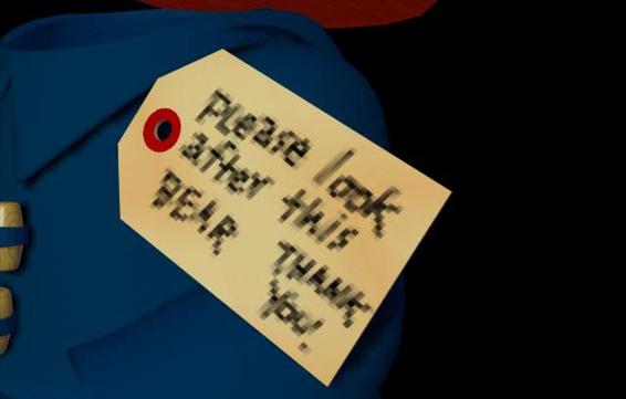
The Causes of Aliasing
Depth Map Shadow Aliasing:
The intention of the filter attributes, discussed earlier, is not to blur the images as a special effect. It may work in certain circumstances for the
mipmap setting coincidentally, but likely will not work for the other
settings. The attributes are meant as an adjustment factor to get the best image quality. For example, the following images show an exaggerated
Filter of 2.6 when applied with mipmap and quadratic filters, respectively.
Notice that exaggerated filter values will result in blockiness of the
quadratic (and higher order filters) textures.
images by Chris Beaumont
Mipmap texture
Quadratic texture
Depth Map Shadow Aliasing:
The Maya 1.0 renderer had image quality problems where the depth map
shadows often display very blocky, shadow borders. Thus as a
workaround, it is recommended that the resolution of the shadow depth
map be increased. This workaround is not ideal since it can increase both
rendering time and memory usage. This problem has been fixed since
Maya IRIX 1.0.1 and Maya NT 1.0, and you should not be employing such
high resolutions any more.
The following example shows a 256x256 resolution shadow depth map,
casting a shadow from a sphere. Note the jaggies at the shadow borders.
Increasing the shading samples will not help the situation.
Technical Overview 5
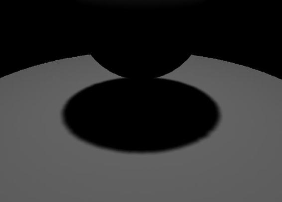
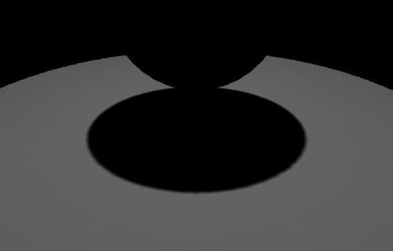
Introduction
Depth Map Shadow Aliasing:
Poor depth map shadow aliasing
To improve the anti-aliasing of such shadow border jaggies, first increase the light's Shape ® Dmap Filter Size. The below image uses a filter size of 3.
The filter size indicates the level of neighboring shadow map pixels that
are used to filter the shadow borders.
Note:
A larger Filter size beyond 4 is not recommended. If more than 4, each shadow sample will need to evaluate far too many neighboring shadow
map pixels. The final image shows even better anti-aliasing, when the
Shape ® Dmap Resolution is set at 512x512.
Filtered depth map shadow
High resolution depth map shadow
6 Aliasing Artifacts in Maya


The Causes of Aliasing
Light Fog Shadow Aliasing:
Finally, if your scene allows you to narrow the cone angle for the spotlight (or reduce the orthographic width of a directional light) without adversely affecting the outcome of the lighting, then you will get crisper shadows
without having to increase the shadow map resolution. This is because the
resolution of the shadow depth map will be focused in a smaller region,
which, in effect, gives it much better resolution.
Light Fog Shadow Aliasing:
Light fog shadows only work with depth map shadows. This is because
the algorithm for calculating light fog shadows projects the view vector
onto the shadow depth map. Then, for each shadow map pixel that the
projected view vector visits, it asks whether it is in shadow or not.
However, since this is needed for each view vector, and traversing the
many shadow depth map pixels can increase rendering time, the renderer
stochastically samples the shadow depth map pixels, capped by the Shape
® Depth Map Shadow Attributes ® Volume shadow samples value.
Note the first image below, where the Depth map resolution is set at 512x512, but the Volume shadow samples is set at only 15. Notice the dicing artifact with respect to the light fog shadows, sometimes capturing the occluding surface's shadow, sometimes not. In an animation, this may
cause flickering artifacts as well. Increasing the shading samples will not help this situation either. But increasing the Volume shadow samples to 50
will produce a much cleaner image, as seen in the second image below.
Note that you should only worry about this attribute when you have small
or skinny surfaces which may miss/hit the light fog shadow computations
For example, if the occluding surface is a big sphere, there would not have been any artifacts.
Aliasing artifacts
Improved aliasing
Aliasing artifacts in fog shadow
Technical Overview 7
Introduction
Motion Blur Visibility Aliasing:
Motion Blur Visibility Aliasing:
To anti-alias motion blurred images properly can be tricky. The renderer
does not use the standard distributed raytracing because it relies on
raytracing and dicing artifacts that are significant. Alias|Wavefront
invented a new (and patented) approach which produces an analytical
solution to the edge anti-aliasing during motion blur.
The following image shows the progression of image quality when certain
attributes are increased. The first image indicates what happens when the
Edge anti-aliasing is set at Low. In this case, all aliasing contains artifacts.
With the next image, the Edge anti-aliasing is set at High. With the next image, Edge anti-aliasing is set at Highest which invokes more shading samples that do a much better job at spatial anti-aliasing. In the final image which uses higher initial Shading samples, and sometimes Visibility samples, the image contains well aliased motion blur. This is elaborated in Maya Software Rendering, Assistant Online [Pearce, Sung].
Low Quality
High Quality
Geometric Aliasing
Spatial
Shading
Aliasing
Highest Quality
Highest Quality
Temporal
Shading
(With 16 shading samples)
Aliasing
Geometric vs. spatial vs. temporal aliasing
Image Plane Aliasing:
If your image plane appears aliased, increasing the global shading samples will not help. The only way to improve the anti-aliasing of the image
planes would be to increase the attribute values of Imageplane ® Shading samples and Imageplane ® Max shading samples. If the image of the image plane matches the resolution of the rendering, then additional anti-aliasing will not be required.
8 Aliasing Artifacts in Maya
The Causes of Aliasing
Check List for other Common Animation Aliasing Artifacts:
Check List for other Common Animation Aliasing Artifacts:
■
Flicker due to screen space or min-screen tessellation. With a surface set at screen space or min-screen tessellation, the tessellation per frame
can be different. When different, you can see flickering, for example,
due to solid textures receiving very different (x,y,z) coordinates to
texture map.
■
Flicker due to filter or filter offset set to very small numbers. This was explained in the file texture section above.
■
Flicker due to very noisy texture(s). With very noisy textures (other than file textures), usually the texture does not know how to anti-alias itself. If it does, it usually has Filter and Filter offset attributes, which you can tweak, as discussed in the file texture section. The
other option is to apply a convert-solid-to-2d-texture operation, in
which a snapshot of the noisy texture is completed to create a file
texture that matches the procedural texture. Rendering with this file
texture, and its ability to anti-alias, may resolve the flickering
problems.
■
Exaggerated aliasing due to incorrect usage of multi-pixel filtering. If your non-filtered rendering already looks aliased, having multi-pixel