filtering turned on will exaggerate the aliasing even more. The multi-
pixel filtering is meant to improve the quality of thinline situations
and when smoothing a good image quality result is needed.
■
Flicker or dicing due to raytracing soft shadows with small number of
shadow samples. Soft shadows occur when Light ® Shadows ® Light radius is non-zero. If soft shadows are desired, it is best to use
shadow depth maps instead of raytrace soft shadows. It will require
many samples to avoid flicker in the raytrace soft shadows, which
becomes very time consuming for the renderer. Raytrace shadows are
useful, as opposed to depth map shadows, mainly when shadows
from transparent objects need to show colored shadows.
Raytraced aliasing artifacts
Check List for Mistaken Aliasing Artifacts:
■
Aliasing due to composite rendering. It is very common mistake to set the Render Globals ®ÊComposite render to On, then noticed that the rendered results look very aliased. This is because the composite
render option is intended to look aliased before compositing, but
should be perfect after compositing. This means that a composite
render does not want to add the residue of the background color into
the pixel result.
Technical Overview 9
Introduction
Conclusion
■
Nickeling artifacts with tessellation. It is very easy to mistake the nickeling found at the edge of a surface as an anti-aliasing problem.
This problem is in fact a tessellation issue and increasing the shading
samples will not help. Rather, select the surface, and increase its
tessellation parameters.
Nickeling
Nickeling at the edge of an object
■
Terminator problem. This is a common artifact in computer graphics, not particular to our software. This staircase of black polygons is due to the combination of coarse tessellation of the surface, and raytracing
shadows. The only workaround for this problem is to increase the
tessellation of the surface.
Staircase
effect
■
You're out of options... Even if you need to increase the Shading samples, don't do it globally yet if this is only a problem for a small, select number of surfaces. Instead, select the troubled surfaces, then
edit the Shape ® Render Stats ® Shading Samples Override ® Shading Samples so that only those surfaces will have their shading samples increased, without having to affect the entire scene.
Conclusion
When setting up a rendering it is important to remember that aliasing may
occur for all of the reasons mentioned in this document. Be sure to try the various methods outlined here to fix aliasing issues before increasing the shading samples and slowing down rendering time. These tips should help
you find the right balance between quality and performance.
10 Aliasing Artifacts in Maya


Assistant Online - Maya/How Tos/Rendering/SW Rendering Overview
Alias|Wavefront / Assistant Online / Maya / How Tos / Rendering / SW Rendering Overview
MAYA SOFTWARE RENDERING:
by Andrew Pearce
A TECHNICAL OVERVIEW
and Kelvin Sung
This document describes some of
the technical details of the Maya
1.0 Software Renderer. It
assumes some technical
knowledge of the inner workings of
a renderer. There are many
sections of this document which
can be helpful to non-technical
people as well.
The document is laid out in two
sections:
The Rendering Pipeline: This section outlines the algorithms
that the renderer uses from the moment it is invoked to the final
pixel output.
Understanding shading networks describes the power of the
Maya shading network and how to tap that power interactively.
It is hoped that this document will give you the knowledge that
will help you to effectively, efficiently and optimally use the
Maya 1.0 Renderer for your production’s needs.
This document is a PDF file and can be view/printed using
Adobe Acrobat Reader.
Your use of this file confirms your agreement to the
Terms and Conditions set out in the Terms and Conditions page.
http://www.aw.sgi.com/assistant_online/entertain/maya/how_tos/rendering/overview_rendering/ [3/7/2000 14:47:46]
Maya Software Rendering:
A Technical Overview
By Andrew Pearce and Kelvin Sung
Alias|Wavefront
a Silicon Graphics Company
AP-M-SWR-01
Maya Rendering: A Technical Overview
Algorithms: Maya Rendering Version 1.0, March 1998
ã September 1998, Alias|Wavefront, a division of Silicon Graphics Limited.
Printed in U S A, All rights reserved.
Assist Publishing Group:
Bob Gundu, Robert Magee
Maya 1.0 Rendering Team:
Sanjay Bakshi, Silviu Borac, Josh Cameron, Jim Craighead, Renaud Dumeur, Antoine Galbrun, Philippe Limantour, Ryan Meredith, Chris Patmore, Andrew Pearce, Joe Spampinato, Kelvin Sung, Chris Thorne, Mamoudou Traore, Greg Veres, Gianluca Vezzadini, Changyaw Wang, Andrew Woo.
A document by Andrew Pearce & Kelvin Sung
Cover image credit: Balloon Girl by Chris Landreth, and the Alias|Wavefront Bingo Team.
The following are trademarks of Alias|Wavefront, a division of Silicon Graphics Limited: AliasÔ
MELÔ
Alias PowerTracerÔ
Alias RayTracingÔ
MayaÔ
Alias MetamorphÔ
Alias QuickRenderÔ
Alias SDLÔ
Maya ArtisanÔ
OpenAliasÔ
Alias QuickShadeÔ
Alias ShapeShifterÔ
Maya F/XÔ
Alias OpenModelÔ
Alias QuickWireÔ
Alias StudioPaintÔ
Maya PowerModelerÔ
Alias OpenRenderÔ
Alias RayCastingÔ
ZaPiT!Ô
The following are trademarks of Alias|Wavefront, Inc.:
Advanced VisualizerÔ
ExploreÔ
MediaStudioÔ
3DesignÔ
Wavefront ComposerÔ
Wavefront IPRÔ
MultiFlipÔ
DynamationÔ
KinemationÔ
VizPaint2DÔ
Graph Layout Toolkit Copyright ã 1992-1996 Tom Sawyer Software, Berkeley, California, All Rights Reserved.
All other product names mentioned are trademarks or registered trademarks of their respective holders.
Any forward looking statements in this document are speculative and are based on current assumptions and in no way imply Alias|Wavefront will at any future time act upon said statements. This document contains proprietary and conÞdential information of Alias|Wavefront, a division of Silicon Graphics Limited, and is protected by Federal copyright law. The contents of this document may not be disclosed to third parties, translated, copied, or duplicated in any form, in whole or in part, without the express written permission of Alias|Wavefront, a division of Silicon Graphics Limited.
The information contained in this document is subject to change without notice. Neither Alias|Wavefront, a division of Silicon Graphics Limited, nor its employees shall be responsible for incidental or consequential damages resulting from the use of this material or liable for technical or editorial omissions made herein.
A l i a s | Wav e f r o n t ❚ 210 King Street East ❚ Toronto, Canada M5A 1J7
Maya Software Rendering
This document describes some of the technical details of the Maya
1.0 Software Renderer. It assumes some technical knowledge of the
inner workings of a renderer. There are many sections of this
document which can be helpful to non-technical people as well.
The document is laid out in two sections:
■
The Rendering Pipeline
■
Understanding the Shading Network.
The Rendering Pipeline on page 1 outlines the algorithms that the
renderer uses from the moment it is invoked to the final pixel output.
Understanding shading networks on page 21 describes the power of
the Maya shading network and how to tap that power interactively.
It is hoped that this document will give you the knowledge that will
help you to effectively, efficiently and optimally use the Maya 1.0
Renderer for your productionÕs needs.
The Rendering Pipeline assumes you have a basic understanding of
rendering algorithms.
Understanding the Shading Network assumes your are familiar with
basic Maya Dependency Graph connections, nodes and attributes.
THE RENDERING PIPELINE
This section outlines the phases and algorithms the Maya 1.0
Renderer uses in order to produce a final image.
Before discussing the steps involved in Maya Rendering, a high-level
overview of the algorithm is in order. The Maya Renderer is a hybrid
renderer. It uses an EAS (Exact Area Sampling) or A-buffer
algorithm for primary visibility from the eye, and then ray traces any
secondary rays.
EAS computes a coverage mask for the geometry in a pixel, which is
more precise than point sampling can produce in all but the most
extreme cases. The improved coverage mask results in better edge
anti-aliasing of the objects in a scene.
Part of the philosophy of the Maya Renderer is that it attempts to
solve each part of the rendering process independently, using the
Technical Overview
The Rendering Pipeline
Step One: Initialize the camera
best method for each rendering problem. Geometric anti-aliasing is solved
with EAS completely before the shading is solved, which is solved
separately from glow, etc.
The Maya Renderer also takes advantage of data cache and instruction
cache locality by making each shading call with a vector of samples. If the shader is called with a single sample, the instructions for the shader must be brought into the instruction cache by the computerÕs CPU, and any data
that that shader uses must be brought into the data cache. Cache memory
works best (fastest) if the next instruction or next data are in the cache. By providing each shader with a vector, or array, of samples, MayaÕs renderer takes advantage of the computerÕs built-in caching mechanism.
When an object is encountered that requires ray tracing to compute some
component of its shading (ray traced shadows, reflections, and/or
refractions), the ray tracer is invoked.
The steps involved in rendering are:
1 Initialize the camera
2 Perform shadow depth map computations
3 Compute geometries that are potentially visible for rendering
4 Compute the tile system
5 Render each tile
a) Compute visibility for stationary objects
b) Compute visibility for moving objects (only if motion blur is selected) c) Compute shading (moving and stationary objects)
d) If highestQuality is selected:
i) Compute Contrast
ii) Compute Extra Shading
6 Composite shaded results
Step One: Initialize the camera
The 3D coordinates of the camera to be rendered are determined by
evaluating the Dependency Graph (DG) at the current time value. The evaluated parameters of the camera are used to compute the perspective
(or orthographic) matrix, and the coordinates of the camera are used to
construct the WorldToEye matrix. Image planes to be used during the rendering phase are tested for existence.
Step Two: Perform shadow depth map computations
Because the Maya Renderer is a hybrid renderer containing both EAS and
ray tracing code, you have the option to either ray trace shadows or to use depth map shadows. This section deals with depth map shadows only,
since the depth maps must be computed as a first pass before rendering,
while ray traced shadows are computed during the rendering phase.
2 Maya Rendering
The Rendering Pipeline
Step Two: Perform shadow depth map computations
The shadow depth map computation is similar to shadow depth map
computations for other renderers you are familiar with. A ÒdepthÓ
rendering is done from the point of view of the light source, and later used during the rendering phase to determine if that light illuminates a given
point (i.e., if the point is obscured by any other object closer to the light, then it is in shadow). For an excellent introduction and overview of depth map shadowing techniques, see SIGGRAPH Ô87 Reeves, Salesin and Cook,
ÒRendering Antialiased Shadows with Depth MapsÓ, pp. 283-291. This section discusses what is unique about the Maya Depth Map Shadows.
In Maya, Depth Map Shadows are available from each of pointLights,
directionalLights, and spotLights.
In the attribute editor for these lights, the Depth Map Shadow section
contains settings to allow you to Read/Write/Reuse Dmap. In all dealings with Depth Map Shadows in the UI, Dmap means Depth Map. These
settings cause the depth maps to be written to or read from disk and
should be enabled when doing iterative render tests on a scene with many
shadows, or when there is only a camera fly-by of the scene (i.e., no
objects move in the area visible to the light). Be aware that if you set these flags when moving objects or moving lights are present, it may cause your
shadows to remain stationary while your objects move in your animation.
Another feature of Depth Map Shadows in Maya is the ability to cast
volume shadows through fog. The shadowing of the fog is done by
examining the shadow map a number of times across the fog volume. The
number of times the fog is sampled is controlled by the attribute
volumeShadowSamples.
Light
Fog Volume
Geometry
Shadow
Viewing Ray
volumeShadowSamples
Figure 1: A side view of a ray penetrating a shadow volume for a spot light.
volumeShadowSamples are taken across the penetration interval.
To automatically get the best resolution out of your depth map, there is an attribute called useDmapAutoFocus. When this attributeÕs value is true, the renderer automatically computes a bounding volume for the objects in the
view from the light source and uses the smallest possible field of view to render the shadow map. This can, however, create artifacts over an
Technical Overview3
The Rendering Pipeline
Step Two: Perform shadow depth map computations
animation if the bounding box of the objects in your scene changes; the
area covered by a shadow map changes, possibly creating aliasing artifacts in your shadows, or unwanted softening or noise in the shadows.
Those familiar with Depth Maps for shadowing know that there are self-
shadowing artifacts that can occur due to the finite resolution of the
shadow map. Only one depth value is stored per pixel and if you happen
to be shading a point on a surface that lies between samples in the depth
map, there is the possibility that the averaged depth from the depth map
will incorrectly shadow the point being shaded. In classical depth map
shadow algorithms, a jitter or bias is added to the depths before
comparison in order to alleviate this artifact. This is also done in Maya.
However, Maya has an additional option called useMidDistDmap which modifies the depth map calculation and eventual use. useMidDistMap is on by default. If the depth map is to be used for purposes other than
shadowing, then it is best to turn this option off. For those with an interest in the specifics of the algorithm, please refer to Graphics Gems III (Academic Press, ISBN 0-12-409670-0) p. 338.
Essentially, Mid Dist attempts to eliminate the need for the jitter or bias parameters by storing the midpoint between the first and second surfaces
visible to the light source in the depth map, rather than simply storing the distance to the nearest surface. By doing this, a larger margin for error is provided, thereby mitigating the incorrect self-shadowing problem. Figure
2 shows a simple side view of a depth map situation. The light source is
shining on a sphere and a plane. In a normal depth map, Z1 (the distance
to the Closest Intersection) is stored in the depth map. When Mid Dist is
enabled, Zmid (the halfway point between Z1 and Z2) is stored in the
depth map.
Distance Stored
z2
zMid
Light
z1
Depth Map
Closest
Next Closest
Intersection
Intersection
Figure2: Diagram of the value stored for the mid distance depth map.
Directional lights can cast depth map shadows in Maya. They have two possible behaviors. Since directional lights are assumed to be at an infinite distance from the scene (hence the parallel light rays), by default
directional lights will cast shadows on the entire scene. The bounding box of the scene is taken and an orthogonal depth map region is created, which contains the entire scene. This can result in shadow depth map resolution
problems if the scene is very large, but only a small section of the scene is 4 Maya Rendering
The Rendering Pipeline
Shadow Computation and Motion Blur
being viewed, or if the scene changes size dramatically over an animation.
To limit the number of objects that are involved in a directional lightÕs
depth map, an attribute named useLightPosition is provided at the top of the Attribute Editor for directional lights. Setting this attribute to true makes the directional light take its position (the location of the directional light icon in the modeling view) into account. Objects in the half space
defined by the lightÕs position and direction are affected by the directional light and are used in the creation of the shadow depth map. Any objects
ÒbehindÓ the directional light are not lit and do not participate in the
generation of the shadow depth map. The useLightPosition attribute is not
on by default because this is a new behavior which may be unexpected by
people coming from other software where directional lights were
infinitely far away regardless of icon position in the scene.
Another way to optimize shadows is to link the lights only to those objects which you wish to cast and receive shadows. You can also avoid casting
shadows from some objects by going to the objectÕs attribute editor and
turning the castsShadows flag off under Render Stats.
Point lights can cast depth map shadows in the Maya Renderer. By
default, these shadows are produced by casting 6 depth maps in each of
the cardinal axes directions (+X, -X, +Y, -Y, +Z, and -Z) from the point
lightÕs position in space. Be aware that if you specify a large shadow depth map resolution, there will be 6 depth maps of that large resolution
generated. Maya does try to compact the depth maps as much as possible,
but large depth maps can still occupy a great deal of memory and take
valuable time to render. To further optimize your shadow depth maps
from point lights, you can turn individual directions off or on. For
example, if there is nothing of interest to cast shadows on the ceiling of your room, you could disable the +Y depth map by un-checking the
useY+Dmap attribute in the Depth Map Shadow Attributes section of the point lightÕs Attribute Editor.
Spot lights by default use only one depth map. Using only one depth map has limitations when the angle of the spot light exceeds 90 degrees; the
resolution of the depth map must be increased dramatically to keep the
shadow quality high. Maya allows you to use up to six depth maps for
spot lights by setting the useOnlySingleDmap check box to false in the Attribute Editor for spotlights. When this attribute is set to false, and the cone angle of the spot light exceeds 90 degrees, five or six depth maps are created around the spot light, tiling the faces of an axis-aligned cube with faces in each of the axis directions - much the same as for a point light. The only difference is that a spotlight will only cast five depth maps if the spot light does not shine onto one of the six faces. Just as cubic reflection maps avoid aliasing at the boundaries between faces of the cube, the cubic
shadow map is also filtered to avoid artifacts.
Shadow Computation and Motion Blur
Basically, shadows do not motion blur in the current renderer. MayaÕs
renderer takes only one geometric position (shutter mid) when sampling
the shadow map, so even though the geometry moves from A to B to C,
the shadow only falls at position B.
Technical Overview5
The Rendering Pipeline
Step Three: Compute potentially visible geometries
Methods to work-around this limitation are to use the Mid-distance
shadow depth map algorithm, or to output the shadow depth map and
process it to add blur before using it in a render.
Ray traced shadows will not work in almost every motion blur instance.
Light
e.g. Shading this position
at Time = 0.7
Position
Position
Position
at Time = 1.0
at Time = 0.5
at Time = 0
Geometry used to compute shadow
Step Three: Compute potentially visible geometries
Gathering the objects to be rendered starts by going to all of the Shading Groups and collecting all of the objects contained in each group. Figure 3
shows that there is a ÒhiddenÓ list associated with each shading group
which is a list of objects or geometries to be shaded using that shading
group. A consequence of this is that if an object is not a member of any
shading group, it is not rendered. Figure 3 also shows that there is a hidden partition (much like a partition which you as a user can create) called the renderPartition which contains the shading groups. The renderPartition is hidden from direct manipulation in the interface; changing an objectÕs
group membership in the renderPartition is done using shading group
assignment in the Multilister.
Displacement
Material
May or may not
Surface
be connected
Material
to Shaders
(material)
Volume
Material
defaultLightList
List of active lights
List of connected geometries
renderPartition
SG
SG
SG
SG
Pre-defined partition
contains all the ÒactiveÓ
SG
SG
SG
shadingGroups
Figure 3: Shading Group Relationships
6 Maya Rendering
The Rendering Pipeline
Step Three: Compute potentially visible geometries
Given this background, and now that the shadow depth maps have been
computed, the rendering pipeline continues as follows:
Computation of Visible Geometries For Rendering
For each shadingGroup in renderPartition
For each geometry in shadingGroup
compute geometryÕs boundingBox in screen space
if (boundingBox touches cameraÕs viewing frustum)
initialize shadingGroupÕs shading network
if (initialization succeeds)
keep the geometry in the renderableGeometrySet
endif
endif
endfor
endfor
Note that the Maya renderer will only initialize a shading network at most once per material. Initializing shading networks does not load file
textures. At this point, the renderer is identifying geometries and their
associated shading networks that may be visible in this frame.
Note:
A similar computation occurs for computing the shadow depth maps;
however, shading networks are not initialized at that point, and
visibility determination also includes light linking criteria.
Displacement shading networks are the exception to this rule - the
displacement must be evaluated during a shadow depth map
computation to generate the proper shadowing.
For determining which geometries possibly intersect the cameraÕs frustum
(frustum is a technical word describing a volume the shape of a pyramid
with its point cut off) MayaÕs renderer looks at the near and far clipping planes. Geometry that penetrates the near clipping plane will be clipped to the near clipping plane. Any part of the geometry nearer to the camera
than the near clipping plane is eliminated from being rendered. Geometry
is not clipped at the far clipping plane in the Maya 1.0 Renderer. If a piece of geometry spans the far clipping plane, it will be rendered in its entirety.
If a piece of geometry is beyond the far clipping plane it will not be
rendered at all. So there is a type of clipping occurring at the far clipping plane, but it is at the object level, not at the triangle level. Figure 4 shows this clipping relationship. Geometry O1 will be cut by the near clipping
plane so that only the portion beyond the near clipping plane is rendered.
Geometry O3 will not be rendered at all since it is beyond the far clipping plane, and geometry O2 will be completely rendered because part of it lies between the camera and the far clipping plane.
Technical Overview7
The Rendering Pipeline
Step Three: Compute potentially visible geometries
O2 (Object 2)
O1 (Object 1)
Near Clipping Plane
O3 (Object 3)
Far Clipping Plane
Figure 4: Near and Far plane clipping; O1 is partially rendered, O3 is not rendered, O2 is completely rendered.
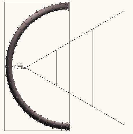
Since MayaÕs renderer uses the bounding box to cull or accept geometry, it is possible that pathological geometries (such as the one diagrammed in
Figure 5) can be unnecessarily placed into the renderableGeometrySet. This will not produce incorrect images, merely waste the time needed to
process the geometry. In Figure 5, the gray ÒCÓ shaped geometry is
unnecessarily placed into the renderable set because its bounding box
intersects the viewing frustum even though the geometry itself does not.
Break the object up into three separate geometries to solve this problem.
Smaller objects shrink the size of the bounding boxes so that they do not
contain the interior of the ÒCÓ.
Near Clipping Plane
Far Clipping Plane
Bounding Box
Figure 5: A grey ÒCÓ shaped object which will incorrectly be placed into the renderable set.
8 Maya Rendering
The Rendering Pipeline
Step 4: Computing the tile system
Step 4: Computing the tile system
The Maya Renderer ÒtilesÓ the image to be rendered into smaller pixel
rectangles. If you have watched the Maya Renderer while it is rendering,
you have seen this tiling pattern; areas of low complexity are rendered
with larger tiles than areas with high complexity. This section describes
why this occurs and how the decision is made about tile sizes.
A goal of the Maya Renderer is to keep the amount of memory used to a
minimum. One of the ways the renderer attempts to achieve that is by
estimating the memory cost of rendering a single tile scanline. A tile is a subsection of an image, and a tile scanline is a single row of pixels in a tile.
The Maya Renderer first uses a number of variables to compute the
maximum allowable number of triangles that can render in a tile scanline.
Factors used in the computation of this number include:
■
is ray tracing enabled?
■
is motion blur enabled?
■
is edgeAntiAliasing enabled?
■
what is the number of shading samples?
■
what is the setting of the Render Globals maxMemoryUse attribute?
■
is multi-pixel filtering on?
■
what is the vector length (the number of samples passed into the
shading nodes)?
From these factors a maxTileCost is derived which represents the
maximum number of triangles believed to be renderable in a single
scanline while still maintaining the given memory limit. Factors that are
not included in the estimation of tile cost are shading network complexity and the size of any file textures required to render the geometry in the tile.
Each object in Maya has a method to estimate how much memory is
required to render it (in terms of triangle counts, number of particles, etc.) in a given screen space window.
The Maya Renderer starts by tiling the screen into four tiles to start with, each one quarter of the image resolution. It then estimates the cost of
rendering each of the tiles in terms of the most complicated scanline
(geometrically speaking) in the tile. If the estimated number of triangles in the most complicated scanline exceeds the maxTileCost, then the tile is subdivided into four new tiles and the same process is applied to each of
them in turn. This continues until the maxTileCost criteria is met, or the tile has reached the minimum tile size of 16x16 pixels.
Note that at this point, no tessellation has occurred; the renderer has
merely collected bounding boxes of the objects in screen space, and gotten estimates from those objects regarding their geometric rendering
complexity. From this information, a tile pattern is created to use when
rendering the scene.
Technical Overview9
The Rendering Pipeline
Step 5: Render each tile
The following pseudo-code describes the tile generation procedure:
create four tiles based on the input image resolution
Foreach geometry in renderableGeometrySet
Foreach tile in tileList
approximate tileCost of geometry
put geometry into the tile, and update the tileCost
if tileCost > maxTileCost
Subdivide tile to create new smaller tiles
put new tiles in tileList
endif
endFor
endFor
Note:
To save memory, the subdivision of tiles is not really done until
rendering begins, but is included in this code for clarity
Step 5: Render each tile
So far, you have learned about the generation of shadow depth maps, the
determination of renderable geometries, and the computation of the image
tiling pattern. The next step in the rendering process is to perform the
visible surface determination given the tile and a list of objects visible in that tile. The visible surface and shading computation is broken down as
follows:
a) Compute visibility for stationary objects
b) Compute visibility for moving objects
c) Compute shading
d) Highest quality setting
- compute contrast
- compute extra shading samples if necessary
Note:
The following sections will discuss non-moving objects and their
shading first (step a), then discuss how adaptive sampling works (steps
c + d), and finally return to discuss computing visibility for moving
objects (step b).
Step a: Compute visibility for stationary objects
The Maya Renderer does not tessellate geometries until it has to.
Tessellation is the process of approximating a NURB surface with
triangles. Tessellation is a required step because the renderer only
knows how to render triangles and volumes, not NURB surfaces. The
process of avoiding tessellation until the renderer knows it will have to
render the object is called lazy tessellation. By doing lazy tessellation, 10 Maya Rendering
The Rendering Pipeline
Step 5: Render each tile
the renderer hopes to avoid tessellating some objects, thus saving on
the associated time and memory consumption that would otherwise be
incurred. So how does lazy tessellation work? First the
renderableGeometrySet is sorted for the tile in order of depth from the camera. Then the renderer only tessellates the front-most surface (or
surfaces if two or more surfaces overlap in Z depth from the camera) in
the hopes that they will fully occlude the more distant surfaces. If this is wrong, then the renderer will continue and tessellate the more distant
surfaces, but in many cases, this saves some amount of work. Figure 6
shows a case where the renderer would first tessellate objects O1 and
O2 - because they overlap in Z depth from the camera, the renderer
must first determine inter-object occlusions, hence the need to tessellate them both - object O3 would not be tessellated since objects O1 and O2
can potentially occlude O3. Tessellation generally applies only to
NURB surfaces, but in the case of displacement mapping, it can also
apply to polymeshes.
O1 (Object 1)
O3 (Object 3)
Z
Objects in this zone
Tile
may not have to be
O2 (Object 2)
tessellated
Figure 6: Depth sorting objects in tiles. Objects O1 and O2 are initially tessellated, while O3 is not, pending visibility determination.
Because the renderer is trying to fully determine visibility before
moving onto the shading phase, if objects O1 or O2 are potentially
transparent (i.e., they have a transparency map or have their
transparency set to a constant, non-zero value) then the renderer has to
assume that they will be transparent and compute the visibility of
object O3.
Tip:
It helps the renderer optimize the scene if you do not attach any nodes
to the transparency channel of a texture when that object can never be
transparent. That way, the shader initialization can flag the objects as
completely opaque and use this optimization.
The visibility of the objects is determined by a method that has a close
analogy to the pushpin array of nails novelty toy you often see in
ÒscienceÓ stores or higher-end games stores. It consists of an array of
blunt nails pushed through a plastic board with a plexiglass front
shield to prevent the nails from being pushed all the way out of the
board. You press your hand or face into the blunt end of the nails, and
the nails on the other side of board take on the shape of your hand or
face.
The EAS algorithm used in Maya is very much like a pushpin approach
where the renderer pushes the triangles into a digital pushpin array.
Technical Overview11
Step 5: Render each tile
The digital pushpin array is many times more dense than the pixel,
which gives us good geometrical anti-aliasing, and our digital pushpin
array remembers which triangle pushed it the furthest towards the
camera so that it can be shaded correctly. The portions of each triangle
that remain visible in each pixel after all this digital pin-pushing are
called fragments. A fragment is simply the shape left by clipping the triangle to the pixel.
Note:
Step b will be explained at the end of this section.
Step c: Compute shading (for stationary objects)
Now that the visibility of all non-moving objects in the scene has been
determined, the renderer needs to shade those objects which still remain
visible in each pixel. Before the renderer starts to shade, though, it must first attempt to merge any triangle fragments from the same object into
a larger fragment. This is done because it is important to shade each
surface as few times as possible in each pixel. However, there are a
number of cases where it is not possible or desirable to do the merging.
If the fragments are from the same surface, but they have different
depths (say you can see the front and back lip of a bowl in the same
pixel, these need to be shaded differently; so the fragments cannot be
merged) or if the triangles are on either side of a sharp edge on an object (say there is a degree one surface or an object which is not smooth
shaded), then it is important to preserve the sharp edges and again, it is not possible to merge these fragments.
Once the fragments are merged, the renderer then shades the merged
fragment shadingSample a number of times as specified in renderQuality or overridden by each object in the Attribute Editor under Render Stats.
The following pseudo-code briefly outlines the merging and shading
process;
For each pixel in the tile scanline
merge all possible fragments for the same object
shade the mergedFragments shadingSample number of times.
endFor
The initialization and evaluation of the shading network is handled in a
different section. For now, the renderer can almost consider the shading
of each fragment as complete.
Note:
If you have animated the camera in Maya then all objects are considered to be moving since the Maya renderer treats the camera as the stationary
point. Therefore if you animate the camera, you must consider the issues
in Step b.
Step d: Highest quality setting
The shading is not complete if highestQuality has been selected in renderQuality. The Maya Renderer tries to shade each object only once 12 Maya Rendering
Step 5: Render each tile
per pixel; however, this is not always a high enough sampling
frequency to properly anti-alias some shading events like thin speculars
or shadow edges. To catch these shading events, the Maya Renderer
provides an adaptive shading option that is enabled when
highestQuality is selected. The Maya Renderer examines the contrast between this pixel and its five already-computed neighboring pixels
(the next scanline is not yet rendered, so all 8 cannot be examined).
Figure 7 shows the five neighboring pixels involved in the contrast
computation.
Current Scanline
Current Pixel
Figure 7: The 5 neighboring pixels used to compute contrast.
If the contrast exceeds the contrast threshold specified in the Contrast
Threshold Attributes section of renderQuality, then additional shading samples are taken. The number of additional shading samples taken
varies between shadingSamples and maxShadingSamples as specified in renderQuality and is overrideable on a per-object basis in the Render Stats portion of the Attribute Editor. A simple linear function is used to determine the number of shading samples. Figure 8 shows a chart of
the function used to determine the number of additional samples to
take. The number of samples starts at shadingSamples (SS) and remains at that number until the contrast threshold is reached. At that point, as
the distance above the threshold increases, so does the number of
shading samples taken until the full contrast of 1.0 is reached and
maxShadingSamples are taken.
Shading
Samples
MaxSS
MaxSS - Max shading samples.
(defined in renderQuality)
Extra
can be overridden by object
Shading
Samples
taken
SS - shading samples
(defined in renderQuality)
SS
can be overridden by object
Contrast
threshold
1.0
Figure 8: Graph showing how the number of extra shading samples for highest quality is computed.
Technical Overview13
Step 5: Render each tile
If you look at the default contrast settings you will see that they are:
Red = 0.4
Green = 0.3
Blue = 0.6
These settings were chosen because they roughly correspond to the
human eyeÕs responsiveness to these wavelengths of light. The human
eye is very sensitive to changes in green, but not very sensitive to
changes in blue.
The computation of contrast is physically based on the contrast
recognition abilities of a monkey eye. While not wanting to start a
debate regarding evolution vs. creation, it is generally accepted that the human eye is very similar to the monkey eye, genetically speaking. The
contrast is computed with the following formula for each of R, G and B:
max
min
I
Ð I
------------- = contrast
max
min
I
+ I
The algorithm for determining if additional samples should be taken is
outlined in the following pseudo-code:
Foreach pixel
examine the pixelÕs 5 neighbors
Foreach object shaded in this pixel
collect (RGBmax) (RGBmin)
compute contrast
if (contrast > threshold)
take additional shading samples
endif
endFor
endFor
Figure 9 shows a simple example for non-moving objects. There are four
images of a spot light shining on a plane. With low quality, both the
geometric edge of the object and the shaded edge of the spot light are
aliased. When high quality is selected, the geometric edges of the object
are anti-aliased; however, the shading edge of the spotlight is still
aliased because no adaptive shading was invoked. When highest quality
is set, both the geometric edge of the object and the shading edge of the
spot light are properly anti-aliased. The final image shows the same
image generated with multi-pixel filtering on. This is a true multi-pixel
filter applied at the sub-pixel level and not a post-process low pass filter that is applied to the pixels. Multi-pixel filtering is discussed further on
14 Maya Rendering
The Rendering Pipeline
Step 5: Render each tile
Low Quality
High Quality
Spatial/Geometric
(No adaptive shading)
Aliasing
Shading Aliasing
Highest Quality
Highest Quality
(With adaptive shading)
(With multi-pixel filtering)
Figure 9: Geometric vs. shading anti-aliasing.
Step b: Compute visibility for moving objects
You have learned how non-moving objects have their visible surfaces
calculated and subsequently shaded, and touched on the methods the
Maya Renderer uses for anti-aliasing stationary geometry and shading.
In this section, you will learn about the rendering of moving objects
and motion blur.
Motion blur is solved with point sampling using a process unique to
Alias|Wavefront. The Maya Renderer chooses pseudo-random
locations on each pixel where it will sample the moving objects as
illustrated in Figure 10.
Current Scanline
Current Pixel
Figure 10: Example sample locations (not actual) for motion blur point sampling.
The number of sample points in each pixel is under user control. The
number of visibility sample points for motion blur is determined by the
motionBlurVisibilitySamples attribute in renderQuality.
The number of motion blur visibility samples cannot be overridden on
a per object basis; however, the contrast is used to increase the number
of visibility samples for motion blur. For highest quality, the five
neighboring samples are examined to compute the coverageContrast,
Technical Overview15
The Rendering Pipeline
Step 5: Render each tile
and additional visibility samples are taken (up to maxVisibilitySamples from the renderQualityÕs Motion Blur Visibility section). While the minimum number of motion blur visibility samples cannot be
overridden on a per-object basis, the maximum number of visibility
samples can be overridden. The Render Stats section of the Attribute
Editor for an object contains a Motion Blur section where this override
can be set.
To compute the coverage and visible surfaces for motion blurred
objects, the Maya Renderer holds the ray stationary, and moves the
triangle across it to see when and where the ray intersects the triangle.
Figure 11 diagrams this procedure. A ray (a point sample) is sent
through the pixel and checked for intersection with a moving triangle
that moves from the left of the pixel at shutter open time, to the right of the pixel at shutter close time. By looking at the triangle itself, you can see that the triangle first intersects the ray at time = .2 and stops
intersecting the triangle at time = .7. These intersection points allow us to form a line in the space of the triangle that describes where the
triangle intersects our point sample. The renderer can then sample this
line (and thus the triangle) at multiple times during the time it covers
this pixel, which is how it supersamples the shading of moving objects.
There are other optimizations which are used in computing motion blur
that are not covered in this document. The important thing to learn
from this section is that in the case of motion blurred objects, the
meaning of shadingSamples is overloaded, which means it is used to control a different type of sampling when motion blur is on versus the
type of sampling it controls when motion blur is off. In the case of
motion blurred objects, shadingSamples controls the number of shading samples in time across the moving triangle(s), as represented by the ÔXÕs
on the triangle in the upper left of Figure 11.
t=0.7
t=0.2
x x x
Pixel
!!shadingSampleÕs meaning
is overloaded!!
Figure 11: Motion blur coverage and shading sampling.
There is no adaptive shading sampling for time-based samples.
Figure 12 shows a simple example of the differences between geometric,
spatial and temporal aliasing, and how various Maya Renderer
parameters anti-alias each of these artifacts. At low quality, all types of aliasing are present; going to high quality eliminates the geometric
aliasing problem. Going to highest quality with one shading sample
16 Maya Rendering
The Rendering Pipeline
Step 5: Render each tile
eliminates the spatial aliasing, and going to 16 shading samples
completely eliminates the temporal aliasing.The checkered plane is
moving from left to right.
Tip:
It is not recommended that you set the shading sample frequency to 16
for all your motion blur scenes, only that you increase the number of
shading samples on objects that display this type of temporal aliasing.
Low Quality
High Quality
Geometric Aliasing
Spatial
Shading
Aliasing
Highest Quality
Highest Quality
Temporal
Shading
(With 16 shading samples)
Aliasing
Figure 12: Geometric vs. spatial vs. temporal aliasing.
In general, it is not possible to separately anti-alias or see if the spatial or the temporal aliasing is causing the artifact; the example in Figure 12
is a bit contrived to be able to show this. Figure 13 shows a more
common case where both the spatial and temporal aliasing are seen in
the same location. In Figure 13, the texture mapped plane is rotated 45
degrees and then moved from left to right across the screen.
Technical Overview17
The Rendering Pipeline
Step 5: Render each tile
Low Quality
High Quality
Geometric Aliasing
Spatial/ Temporal
Shading Aliasing
Highest Quality
Highest Quality
Temporal
(performs spatial
Shading
(With 10 shading samples)
shading anti-aliasing)
Aliasing
Figure 13: Spatial and temporal aliasing can not always be separated.
Step 6: Composite shaded results
At this point the renderer has a list of shaded fragments for each pixel. The next task is to composite the fragments together to form a single pixel color that represents the geometry visible in that pixel.
If multi-pixel filtering is not enabled, the result is simply a box filtering of the fragments. The fragmentÕs color is multiplied by the amount of the
pixel it covers, and then all fragments are added together, or to put it a different way, the fragment colors are weighted by their coverage
contribution and then summed.
If, however, multi-pixel filtering is enabled, then a 3x3 pixel filter kernel is used to combine the fragments. The 3X3 pixel filter kernel is a cubic spline filter kernel derived by convolving a square pulse with itself three times.
The shape of this filter roughly approximates a gaussian filter. Figure 14
shows a graphic diagram of this filter. The fragment marked with the bold
circle inscribed with an ÔXÕ is weighted according to the volume contained between it and the projection of the fragment onto the filter kernel. This is a true multi-pixel filter and not a post-filter; the fragments for all of the 3x3
pixels are weighted before pixel composition.
18 Maya Rendering
Working with BOT or Cached File Textures
Pixel
Figure 14: The 3x3 multi-pixel filter
Working with BOT or Cached File Textures
BOT (Block Order Textures) are enabled by selecting useTextureCache on each file texture. If this flag is ON and the file textures are not already BOT format files, then Maya will automatically create BOT textures from
your images files in the TMPDIR (temporary directory).
If the textures are already in BOT format (you can convert them using the
stand-alone utility makebot) then no conversion is required, the state of the useTextureCache flag is irrelevant, and BOT textures will be used.
A BOT texture on disk is a compressed MIPMAP structure with 8x8 texel
pages. (A texel is a texture element derived in much the same way as pixel is a picture element). The textureCache is a 256 texel page cache in memory; that is, it can hold 256 of the 8x8 texel pages. There is only one textureCache for the entire rendering session, and the cache is shared between all file textures.
The textureCache is demand loaded. When a part of a texture is required, if it is not already in the cache, then it is loaded from disk. If the textureCache is full, then the least recently accessed pages are removed and replaced
with the pages being loaded.
Tip:
BOT textures have the advantage of reducing the amount of memory
required to keep textures in memory, and they employ algorithms that
help ensure a high hit ratio when looking for a part of a texture. If the
image file has already been converted to a BOT texture file, then the
Maya renderer can use it much more quickly than when it has to
convert the file to BOT texture on its own. If you have lots of textures,
or very big textures, then converting to BOT textures may be a useful
way of conserving memory.
BOT textures do have some limitations as well. The image viewing
utilities fcheck and wrl do not know how to display a BOT texture as it is not a standard image format. If multiple renderers are using the same
BOT file (whether those renderers are on a multi-processor machine or on
Technical Overview19
Other renderGlobal Optimization Parameters
a separate machines.), there can be an I/O bandwidth problem as all of
these renderers attempt to access the same file on the same disk. This will cause the renderers to slow down. The only solution to this problem is to
ensure each renderer is accessing it's own local copy of the BOT texture,
where each BOT texture resides on a separate hard disk from all the other
BOT textures. If the image files are not BOT texture files to begin with,
then TMPDIR can get full quickly with all of the temporary BOT files.
BOT file
(on disk)
8x8
page
256 slots
textureCache (in Memory)
Other renderGlobal Optimization Parameters
useFileCache swaps the least recently used (LRU) render data in memory out to a disk file in TMPDIR. At the start of rendering, Maya will compute the maximum size this swap file can become by setting its maximum size
to 80% of the free space on TMPDIR. This is done to avoid filling up the
disk and leaving no space for other processes which require TMPDIR
space.
As the renderer consumes more memory,the least recently used sections of
data are swapped out to the swap file by the renderer. This does not
involve any operating system context switch or swapping.
Data items which are candidates for swapping are tessellated triangles and raytracing spatial subdivision structures (voxels).
If, for some reason, swapping data to this swap file fails (i.e., the swap file has reached its maximum size), then the data is simply thrown away and
re-calculated if required again at a later stage of the rendering.
By having Maya do the swapping, it should be a little more intelligent
about it than the operating system, which has no knowledge of what the
renderer is doing.
Disadvantages are I/O bandwidth problems, which get worse if there are
multiple processes on a single multi-processor machine and they are all
accessing the same TMPDIR. You could run out of disk space and not be
able to save your images.
Therefore, if the rendererÕs output image directory and TMPDIR are on the
same disk partition, saving of image files may fail. The likelihood of this data loss increases as more frames of the animation are rendered.
20 Maya Rendering
Understanding shading networks
Other renderGlobal Optimization Parameters
Tip:
When using useFileCache, it is better to therefore render to a different disk than the disk containing the TMPDIR.
UNDERSTANDING SHADING NETWORKS
This section describes basic concepts that are important to make the most
use of the power of the Maya RendererÕs shading network.
First, let us define some terms.
■
shading network - a connected graph of nodes that can be used to
shade objects. These networks generally contain what Maya classifies
as materials and textures, but they do not have to contain these
nodes.
■
shadingGroup - a collection of objects to be shaded with the shading network attached to the surfaceMaterial port of the shadingGroup if the object is a surface, or with the shading network attached to the
volumeMaterial port of the shadingGroup if the object is a volume.
■
port - an attribute on the shadingGroup, which acts as an input for shading networks. These attributes differ from normal connected
input attributes because the renderer evaluates these inputs for
required connections.
■
material - these are similar to what were called shaders in Alias and Explore. They are called materials in Maya to avoid any functional
associations that the word ÔshaderÕ might imply.
The shading network is designed as a data flow network. As you look at
shading networks in the Hypergraph, data is fed in the left side of the
network and a final shaded result emerges from the right-most node.
A Shading Group can have a different shading network attached to both
the surfaceMaterial port and the volumeMaterial port. Surfaces that are in this shadingGroup are shaded with the network attached to the
surfaceMaterial port, while volumes that are in this Shading Group are shaded with the network attached to the volumeMaterial port. A shading network assigned to the displacementMaterial port affects only surfaces and only during tessellation (unless it is otherwise connected to the surface
shading network as well as being attached to the displacementMaterial
port).
Note:
The Maya Renderer uses specially named attributes to supply shading
networks with information about the sample point being shaded.
Technical Overview21
Understanding shading networks
Other renderGlobal Optimization Parameters
Note:
For a list of the specially named attributes that the Maya Renderer uses
to supply information to a shading network, see the Maya online
documentation ® Maya DeveloperÕs Tool Kit ® Maya API Overview for writing Shading Nodes ® Appendix C, ÒRendering attributesÓ.
If a shader declares an attribute with one of these special names, the
attribute is automatically fed that information at shading time during
rendering. This is called an implicit connection and is similar to accessing global variables in RenderManÕs shading language.
For example, if an attribute on a node is called pointCamera and that attribute is not connected, then when that attribute is queried during the shading computation, the intersection point in camera space will be
provided to that attribute, since this is a specially named attribute.
If an unconnected attribute exists anywhere in the shading network and
the attribute has one of the special names listed in the appendix, the
attribute will be filled with the requested information at shading time
during rendering.
Tip:
You can override the implicit behavior of any specially named attribute
simply by explicitly connecting something to that attribute.
outAlpha
bumpValue
outNormal
normalCamera
normalCamera
Figure 15: Overriding normalCamera for bump mapping.
Bump mapping in Maya works by overriding the normalCamera attribute on materials. The normalCamera is the normal of the surface in camera space. A similar naming convention is followed for other Maya specially
named attributes. Figure 15 shows the manner in which the normalCamera for a material is overridden. Maya supplied materials have an attribute
called normalCamera; usually normalCamera is unconnected and the normal in camera space of the intersection point is supplied to the shader. When
the material is bump mapped, a bump node is connected to the
normalCamera attribute. The bump node has two input attributes:
normalCamera, which will normally be unconnected, and a bumpValue attribute. The final outNormal from the bump node will be the normal in camera space modified (bump mapped) by the texture map.
Note:
Because of the way Maya supplies data to unconnected, specially named
attributes, the bump node must also be connected to any reflection maps
you have on your material, so that both the material and the reflection
map are using the same bumped normal. This type of connection is
22 Maya Rendering
Understanding shading networks
Other renderGlobal Optimization Parameters
shown in Figure 16. The attribute outNormal of the bump node is fed both into the materialÕs normalCamera as well as the environment
textureÕs normalCamera.
normalCamera
outNormal
normalCamera
outAlpha
bumpValue
outNormal
reflectedColor
normalCamera
outColor
Figure 16: Material and environment map sharing the same bump map.
Note:
You do not need to program API shading nodes to access all the
attributes provided to the shaders.
You can access any of the specially named attributes by adding a dynamic
attribute onto any node, provided that the attribute has the same name
and data type as listed in the appendix.
Adding all of these dynamic attributes can be time-consuming, and may
result in many different nodes with the same dynamic attributes defined,
so to make accessing sample data easier, there is a helpful node provided
in the Create Render Node window called sampleData, which is simply a node with many of the specially-named attributes already defined on it.
You can create just one of these sampleData nodes and connect from its attributes to every place in your shading network that requires the
information. Any attribute you require that is not already defined on the
sampleData node can be added as a dynamic attribute of the same name and type.
Creating just one sampleData node with all the attributes you require is an effective way to create a kind of global variable list. Of course, there is nothing wrong with creating multiple sampleData nodes to reduce
confusion, if the attributes will be connected into many shading networks.
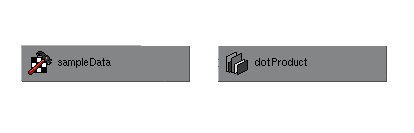
normalCamera
input1
outValue
rayDirection
input2
Figure 17: Using sample data to take the dot product of the ray and normal.
Technical Overview23
Understanding shading networks
Other renderGlobal Optimization Parameters
In Figure 17, the normal in camera space and the incident ray direction are supplied by the sampleData node and connected to the two inputs of a dotProduct node, the results of which are to be used elsewhere in the shading network.
Since the dot product is an important component of many shading models, it can be seen that Maya allows for the prototyping of shaders without
actually coding them in C++.
Note:
Just as there are specially named input attributes, there are specially
named output attributes.
A node must have at least one of the following specially named output
attributes to be a valid node to directly connect to a surfaceMaterial port of a shadingGroup:
■
outColor
■
outTransparency
■
outGlowColor
If the node connected to the surfaceMaterial port of a shadingGroup does not have at least one of the above attributes, none of the surface objects assigned to that shadingGroup will render.
It does not matter which attribute of a node is connected to the
surfaceMaterial port of a shadingGroup; only the outColor, outTransparency and outGlowColor attributes of the connected node will be used. Even if the message port is used to attach a node to the surfaceMaterial port, the shadingGroup will look for outColor, outTransparency and outGlowColor attributes on the attached node.
A node must have at least one of the following specially named output
attributes to be a valid node to connect to the volumeMaterial port of a shadingGroup:
■
outColor
■
outTransparency
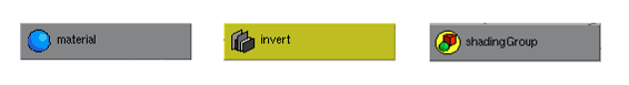
Creating special effects, such as inverting a materialÕs color after shading, requires that you attach a special node with outColor, outTransparency and/
or outGlowColor attributes to the surfaceMaterial port of the shadingGroup.
A special node called surfaceShader is provided in the Create Render Node window available in the multilister. This is a light weight Òpass-throughÓ
node that simply allows you to translate the names of the nodeÕs outputs
to the names required for it to be a valid surfaceShader.
24 Maya Rendering
Understanding shading networks
Other renderGlobal Optimization Parameters
in
out
outColor
outTransparency
outGlowColor
outColor
outTransparency
outGlowColor
Figure 18: Renaming output attributes using a surfaceShader node.
In Figure 18, the shading group is attached to a surfaceShader node.
Although most of the attributes have the same names, the outColor of the material is passed through an invert node which does not have a properly
named attribute, so the surfaceShader node is required to rename that one attribute. The surfaceShaderÕs outTransparency and outGlowColor are attached directly to the materialÕs outTransparency and outGlowColor, so these values go to the shadingGroup unchanged, directly from the
material. The outColor of the material, however, is first passed to the in attribute of an imaginary (a node made up for this example) invert node, which inverts the color and then places the result in the out attribute. The out attribute is then connected to the outColor of the surfaceShader node where it is passed through to the shadingGroup.
The surfaceShader node is simply a means to translate an arbitrary network of Maya or user-written nodes with arbitrarily named output attributes
into what the renderer will recognize as a shading network with which it
can render objects. Of course, you can always create three dynamic
attributes on the invert node and make connections from the material and a loop back connection from the out attribute to the dynamic outColor attribute on the invert node, as shown in Figure 19.
outColor
in
out
outColor
outTransparency
outTransparency
outGlowColor
outGlowColor
Figure 19: Invert node with 3 dynamic Òpass-throughÓ attributes.
There is also a volumeShader node provided for the same reasons.
Technical Overview25
Understanding shading networks
Other renderGlobal Optimization Parameters
26 Maya Rendering


Assistant Online - Maya/How Tos/Rendering/Realistic Glass
Alias|Wavefront / Assistant Online / Maya / How Tos / Rendering / Realistic Glass
HOW TO CREATE
by Alias|Wavefront
REALISTIC GLASS
Maya Complete
Rendering
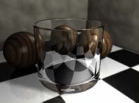
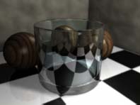
In this lesson, you will learn
how to create a glass shader
that uses a samplerInfo
node and several blendColor
nodes to add more realism
than is possible with the
material node alone.
Play Movie [~246kb]
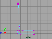
STEP ONE
Create a profile curve for
the glass. Make the profile
so that it creates a surface
for both the inside and
outside of the glass. This
double surface will create a
more realistic effect when
you later add refraction to
your scene.
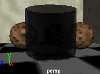
STEP TWO
Revolve the curve to create
the glass.
Set up a simple scene with
some props. These will be
useful to evaluate the
refractive qualities of the
surface.
Don't forget to add lights to your scene.
http://www.aw.sgi.com/assistant_online/entertain/maya/how_tos/rendering/realistic_glass/ (1 of 5) [3/7/2000 14:48:15]


Assistant Online - Maya/How Tos/Rendering/Realistic Glass
STEP THREE
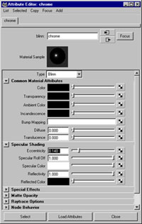
Open the Hypershade. Select Create -> Material -> Phong to create a phong material node. Open up the node in the
Attribute editor and set the following:
Color to Black;
Transparency to White;
Diffuse to 0;
Translucence to 0;
Cosine Power to 50;
Under Raytrace Options set the following:
Refractions to On;
Refractive Index to 1.33;
Refraction Limit to 6;
Reflection Limit to 1.
These settings offer the desired qualities for glass.
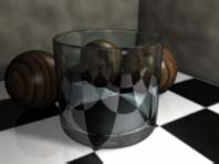
STEP FOUR
Assign the phong shading
group to the glass. Now you
can test render the scene to
evaluate this basic glass
shader.
To raytrace the glass, you
must follow the steps
outlined in How to set up reflections and refractions. The reflections and refractions lesson will teach you how to set up
critical attributes on your various props to ensure that they are
reflected and refracted properly. You will also learn how to set
up your Render Globals for raytracing.
STEP FIVE
In the Hypershade, select Create -> Create Render Node. This will open the Create Render Node window. and under the
Utilities tab, create the following utility nodes:
3 Blend Color nodes,
1 Sampler Info node
The Sampler Info node is a special utility node that returns
values when a point is sampled on a surface during rendering.
These values can be mapped to other nodes to create unique
effects. In this lesson, the Sampler info node will control the
blending of two colors in each of the three Blend Color nodes.
Rename the three Blend Color nodes to the following:
colorBC, reflectBC, transpBC
http://www.aw.sgi.com/assistant_online/entertain/maya/how_tos/rendering/realistic_glass/ (2 of 5) [3/7/2000 14:48:15]


Assistant Online - Maya/How Tos/Rendering/Realistic Glass
This will help you distinguish the purpose of these nodes as you
build the glass shading network.
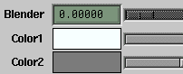
STEP SIX
In the Hypershade, drag the
samplerInfo node onto the
colorBC node. The
Connection editor will open.
Connect the Facing Ratio
attribute to the Blender
attribute.
The Facing Ratio attribute
returns a value between 0
and 1 based on how much
the sampled point is facing
the camera. If you were
looking at a cylindrical glass
head on, the Facing Ratio values would go from 0 at the sides of
the glass to 1 at the center.
Repeat this step two more times to connect the samplerInfo
node's Facing Ratio attribute to the Blender attribute belonging to the reflectBC and the transpBC nodes. Now the samplerInfo node is connected to all three Blend color nodes.
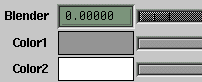
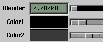
STEP SEVEN
Open up the transpBC node
in the Attribute editor. Set
Color1 and Color2 as
shown here. This will create
a blend from light gray to
white.
Drag the transpBC node
onto the phong shading
group.
In the Connection editor,
connect the transpBCs
Output attribute to the
phong's Transparency Attribute.
Now the transparency of the glass will appear stronger at the
center of the glass and slightly less transparent at the edges.
Test render to compare the results. You may want to darken
the gray blend color to make the edges even less transparent.
Note: The value of the blending colors [1.0 for white and
approximately 0.8 for the light gray] will be used to set the
transparency value. To find out the value of a color that you
choose, open the Color editor and look at the Value that is
http://www.aw.sgi.com/assistant_online/entertain/maya/how_tos/rendering/realistic_glass/ (3 of 5) [3/7/2000 14:48:15]


Assistant Online - Maya/How Tos/Rendering/Realistic Glass
shown as part of Hue, Saturation and Value. A similar mapping
of color values will apply to setting the reflectivity of the glass.
STEP EIGHT
Open up the reflectBC node
in the Attribute editor. Set
the Color1 and Color2 as
shown here. This will create
a blend from white to light
gray.
Drag the reflectBC node
onto the phong shading
group.
In the Connection editor,
connect the reflectBC's
Output R attribute to the
phong's Reflectivity Attribute.
Now the reflectivity of the glass will be strongest at the edges of
the glass and slightly less strong where the glass faces the
camera. Test render to compare the results. You may want to
darken the two blend colors to lower the amount of reflection on
the glass.
STEP NINE
Open up the colorBC node
in the Attribute editor. Set
the Color1 and Color2 as
shown here. This will create
a blend from black to dark
gray.
Drag the colorBC node onto
the phong shading group.
In the Connection editor,
connect the colorBC's
Output R attribute to the
phong's Color Attribute.
Now the color of the glass will be black at the edges of the
glass and a dark grey where the glass faces the camera. Test
render to compare the results. You may want to change the two
blend colors to alter the colors of the glass.
http://www.aw.sgi.com/assistant_online/entertain/maya/how_tos/rendering/realistic_glass/ (4 of 5) [3/7/2000 14:48:15]


Assistant Online - Maya/How Tos/Rendering/Realistic Glass
CONCLUSION
You now have a glass rendering that uses Maya's utility nodes
to create subtle reflection and refraction effects. You can easily
alter the look of the glass by editing the various blend colors to
suit your needs.
To view the completed scene, download the following file:
Your use of this file confirms your agreement to the
Terms and Conditions set out in the Terms and Conditions page.
http://www.aw.sgi.com/assistant_online/entertain/maya/how_tos/rendering/realistic_glass/ (5 of 5) [3/7/2000 14:48:15]


Assistant Online - Maya/How Tos/Rendering/Reflections + Refractions
Alias|Wavefront / Assistant Online / Maya / How Tos / Rendering / Reflections + Refractions
HOW TO SET UP RAYTRACED
by Robert Magee
REFLECTIONS AND REFRACTIONS
Maya Complete
Rendering
In this lesson, you will
learn how to set up a
scene for reflections and
refractions.
Both of these effects
require Raytracing and
they also require that
objects in the scene be
set up properly.
This example will deal with both these qualities at the same
time. In other cases you might want only reflections or only
refractions. The workflow would be similar. You would only
have to focus your attention on the effect that you are most
concerned with.
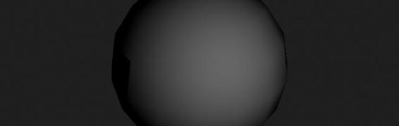
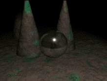
STEP ONE
Create or import a shader
that has reflective and
refractive qualities. Take a
in the library for some
examples. Shown below
is a sample image before
it has been prepared for
reflections and
refractions.
You will require a material node that has either Reflectivity for
reflections or Transparency for refractions. Phong and Blinn have both of these attributes.
For reflections, you must set the Reflectivity attribute on the
material node of your shader. You need to also set the number
of reflections in the Raytrace Options section of the material
http://www.aw.sgi.com/assistant_online/entertain/maya/how_tos/rendering/reflect_refract/index.html (1 of 3) [3/7/2000 14:48:22]

Assistant Online - Maya/How Tos/Rendering/Reflections + Refractions
node. In most cases 1 or maybe 2 reflections will be all that are required.
For refractions, your material will require Transparency and,
under Raytrace Options, you will need to turn on Refractions
and set the Refractive Index. The refractive index should be
set based on the material you are trying to simulate. Below are
some guidelines for Index values:
Material
Refractive Index
Standard Glass
1.2
Quartz
1.46
Crown Glass
1.52
Diamond
2.4
The Refraction Limit should be set to at least the number of
refractive surfaces that will overlap at any one time in the
rendering. A simple sphere would have the front and back
surface, therefore a setting of 2 would be required. If you had
two spheres overlapping then you would need a setting of 4.
STEP TWO
Once your material has
been built and assigned
to your object then you
must set up the other
objects in the scene.
Select objects such as
the wall or the floor that
you want to reflect and refract through the glass.
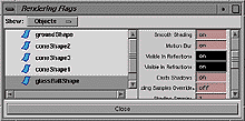
Using either the Attribute editor (one node at a time) or the
Rendering Flags window (multiple nodes), turn the Visible in
Reflections and Visible in Refractions to On.
Note: This is a very easy step to forget therefore watch out for
it when you want reflections/refractions. Also remember that the
Visible in... settings are not required on the object that is doing the reflecting/refracting but rather on the surrounding objects
that will be reflected/refracted by that object.
http://www.aw.sgi.com/assistant_online/entertain/maya/how_tos/rendering/reflect_refract/index.html (2 of 3) [3/7/2000 14:48:22]


Assistant Online - Maya/How Tos/Rendering/Reflections + Refractions
STEP THREE
Now open up the Render
Globals and click on the
Render Quality tab.
From the Raytracing
section, set the following:
Enable Raytracing to On;
Reflections to 1;
Refractions to 2.
Earlier you set Reflections and Refractions for the shading
group's material node. The renderer will use the lower of either
the material node's setting or the Render Global setting. For
example, if the material node had a reflection setting of 3 and the Render Globals set Reflections to 1 then only 1 reflection would occur.
This lets you control these settings either locally at a material
node by material node basis or globally using the Render
Globals.
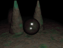
CONCLUSION
Now you can render
your scene with
reflections and
refractions. Remember
that Maya's renderer is
a selective raytracer.
This means that only
objects with shaders
that exhibit raytrace
qualities, such as
reflectivity and
refractions, will be raytraced.
Your use of this file confirms your agreement to the
Terms and Conditions set out in the Terms and Conditions page.
http://www.aw.sgi.com/assistant_online/entertain/maya/how_tos/rendering/reflect_refract/index.html (3 of 3) [3/7/2000 14:48:22]
http://www.aw.sgi.com/assistant_online/entertain/maya/how_tos/rendering/reflect_refract/img/reflect_02.gif http://www.aw.sgi.com/assistant_online/entertain/maya/how_tos/rendering/reflect_refract/img/reflect_02.gif [3/7/2000 14:48:27]
http://www.aw.sgi.com/assistant_online/entertain/maya/how_tos/rendering/reflect_refract/img/reflect_03.gif http://www.aw.sgi.com/assistant_online/entertain/maya/how_tos/rendering/reflect_refract/img/reflect_03.gif [3/7/2000 14:48:29]


Assistant Online - Maya/How Tos/Rendering/Reflection Mapping
Alias|Wavefront / Assistant Online / Maya / How Tos / Rendering / Reflection Mapping
HOW TO CREATE A BALL ENV
By Steve Christov
REFLECTION MAP
Maya Complete
Rendering
In Maya, reflections can
be achieved in one of two
ways. You can either
raytrace the scene or you
can map the reflected
color attribute using an
environment shader.
In this lesson, you will
learn how to render realistic reflections without needing to
raytrace every frame of the animation. Using a ball env. shader,
you can raytrace one image then reapplied it as a map to the
shader's reflectivity.
This is an update for Maya from a previous Assistant article
" Reflection Mapping" by Lorna Saunders, Assistant issue No 3, Winter 1997.
STEP ONE
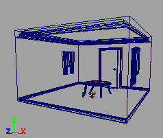
For any reflections you
will need to use a
digital set. The set
must be enclosed in
that it is not 3 sided,
and needs to cover
the area behind the
camera.
Download and
uncompress the file:
[NT ~2 megs.] or,
[IRIX ~2megs.]
http://www.aw.sgi.com/assistant_online/entertain/maya/how_tos/rendering/reflection_map/ (1 of 6) [3/7/2000 14:49:09]


Assistant Online - Maya/How Tos/Rendering/Reflection Mapping
This is a simple set that will be used to demonstrate basic
reflections.
You will notice that the various objects are assigned to several
layers. Select the ball layer and with your right mouse button select Template.
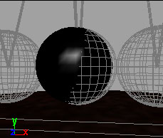
STEP TWO
Create a Sphere.
Position the sphere so
that it is in the same
location as one of the
balls for the pendulum.
Scale the sphere to
make it roughly the size
of one of the balls.
STEP THREE
You now need to give this
sphere a chrome-like
shader.
In the Hypershade, Create
a Blinn material. Name it
Reflector and assign it to
the sphere. Set the
following values in the
Attribute Editor.
Color
●
to Black
Diffuse
●
to 0.0
Eccentricity
●
to 0.14
Specular Roll off
●
to
1.0
Specular Color
●
to
White
Reflectivity
●
to 1.0
http://www.aw.sgi.com/assistant_online/entertain/maya/how_tos/rendering/reflection_map/ (2 of 6) [3/7/2000 14:49:09]

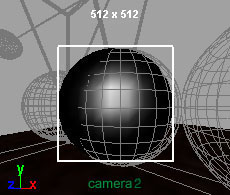
Assistant Online - Maya/How Tos/Rendering/Reflection Mapping
STEP FOUR
Create a new camera and
toggle a panel to look
through it. It should be
called camera 2.
In your Render Globals,
set up the globals to
render from your new
camera. In the Resolution
section change the size to
be 512 X 512. Turn off
Lock Device Aspect
Ratio. The reason for this
is because the env sphere
needs to be a square
image with the chrome ball
as its focus.
Name the output image
Reflection, and in the
Raytracing section turn
Raytracing to On.
Set camera 2 as your render camera.
STEP FIVE
In your persp view,
Select the camera and
move it using the move
tool to position it to look
directly at the ball. Open
the Attribute Editor and
set a narrow angle of
view to around 20. This
will decrease the
distortion around the
edges. Switch to the new camera view and select View ->
Camera Settings -> Resolution Gate.
Set up a two panel view where you can see the persp and
Camera 4. Position your camera in the persp window so that
the ball touches all four sides of the resolution gate of camera 1.
It is important to keep the camera parallel to the ground so that
it looks straight at the reflector. Make sure there is no Y
rotation on the camera.
Batch Render the image.
http://www.aw.sgi.com/assistant_online/entertain/maya/how_tos/rendering/reflection_map/ (3 of 6) [3/7/2000 14:49:09]

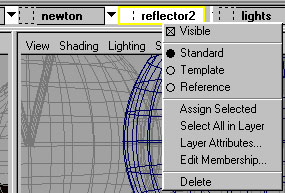

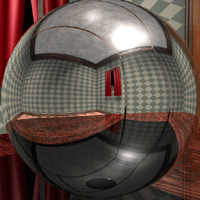
Assistant Online - Maya/How Tos/Rendering/Reflection Mapping
STEP SIX
In your scene it
is a good idea
to put the
camera and the
chrome ball in
its own layer so
that you can
hide them and
come back to
them later if you
need to.
Make sure your layer bar is shown by selecting Options ->
Layer Bar.
Create a new layer. Name it reflector. Select the camera and the chrome ball. In the layer bar move your mouse over the
reflection layer, click with your right mouse button, and select
Assign Selected. Again with your right mouse button, select
Visible.
This will hide the camera and chrome ball so that it does not
clutter your scene.
STEP SEVEN
In the Hypershade window,
select the reflector shader
you made and select Edit ->
Duplicate -> Shading
Network. Rename the
material to reflection_color.
In the Attribute editor, click
on the Map button beside
Reflected Color. In the
Environments Section,
select Env Ball. In the
http://www.aw.sgi.com/assistant_online/entertain/maya/how_tos/rendering/reflection_map/ (4 of 6) [3/7/2000 14:49:09]
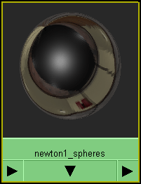

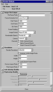

Assistant Online - Maya/How Tos/Rendering/Reflection Mapping
Attribute editor window, Click beside Image, and select File in the Create Node Window. In the Attribute editor for the File,
click on the folder beside image name and Select the image
reflection.iff. By default, this image will be located in the images folder in your project directory.
NOTE: Many times reflections are not perfect, to achieve a
blurred effect, import the file into a paint program to add some
blur. For the final animation, the file was blurred slightly.
STEP EIGHT
At this point you should see
the material node updated
in the Hypershade. Notice
that the color is not
changed but enhanced
when you add the effect of
reflections.
Untemplate the Newton
layer by selecting it and
using the right mouse
button to click on
Standard.
Assign the new material to
the balls layer.
STEP NINE
In the Render globals,
turn Raytracing to Off.
Rename the final render.
Set your
Frame/Animation Ext. to
start at frame 1 and end
at frame 165. Pick the
camera1 as your
renderable camera.
You are now ready to
render the scene.
http://www.aw.sgi.com/assistant_online/entertain/maya/how_tos/rendering/reflection_map/ (5 of 6) [3/7/2000 14:49:09]


Assistant Online - Maya/How Tos/Rendering/Reflection Mapping
CONCLUSION
[MPEG 800k]
By using the ball method
to create a reflection map
you can save on total
render time when
rendering multiple frames
for an animation. While this may not work in all cases, it does
offer an alternative to raytracing a scene.
You could also use different resolutions for your ball image
depending on the size of the object and the distance from the
camera, but generally you'll want to keep the resolution at
either 256 x 256 or 1024 x 1024. In the final animation the
shading samples have been increased to 4 instead of 1. This
helps to reduce some flickering that was encountered when
the final animation was rendered.
Take a look at the following examples for rendering an animation of 165 frames on a Pentium III with 512 megs ram.
Scene using reflection mapping. Time:
●
1 hour 28
minutes.
Scene using selective raytracing only on the balls in the
●
pendulum. Time: 3 hours 19 minutes.
One thing to keep in mind is that reflections are used to
enhance realism and most times you only need to see
general contrast and shapes to produce the effect of a true
reflection as more often than not the viewer is concentrating
on the animation rather than reflections.
Use of this file confirms your agreement to the Terms and Conditions
set out on the Terms and Conditions page.
http://www.aw.sgi.com/assistant_online/entertain/maya/how_tos/rendering/reflection_map/ (6 of 6) [3/7/2000 14:49:09]
http://www.aw.sgi.com/assistant_online/entertain/maya/how_tos/rendering/reflection_map/img/three.jpg http://www.aw.sgi.com/assistant_online/entertain/maya/how_tos/rendering/reflection_map/img/three.jpg [3/7/2000 14:49:16]
http://www.aw.sgi.com/assistant_online/entertain/maya/how_tos/rendering/reflection_map/img/four.gif http://www.aw.sgi.com/assistant_online/entertain/maya/how_tos/rendering/reflection_map/img/four.gif [3/7/2000 14:49:18]
http://www.aw.sgi.com/assistant_online/entertain/maya/how_tos/rendering/reflection_map/img/four.jpg http://www.aw.sgi.com/assistant_online/entertain/maya/how_tos/rendering/reflection_map/img/four.jpg [3/7/2000 14:49:22]
http://www.aw.sgi.com/assistant_online/entertain/maya/how_tos/rendering/reflection_map/img/nine.gif http://www.aw.sgi.com/assistant_online/entertain/maya/how_tos/rendering/reflection_map/img/nine.gif [3/7/2000 14:49:25]


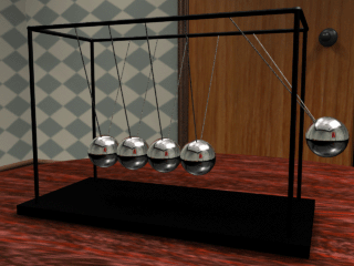
Assistant Online - Maya/How Tos/Rendering/Env Ball vs. Raytrace
Alias|Wavefront / Assistant Online / Maya / How Tos / Rendering / Env Ball vs. Raytrace
Env Ball Render vs. Raytracing
By Steve Christov
Reflection Map
View the final animation using Reflection map - reflection.mpg
[800k]
Time to render 165 frames on Pentium III w/ 512 meg ram: 1 hr
28 min.
Raytracing
View final animation using Raytracing - raytrace.mpg [800k]
Time to render 165 frames on Pentium III w/ 512 meg ram: 3 hr
19 min.
http://www.aw.sgi.com/assistant_online/entertain/maya/how_tos/rendering/reflection_map/chart.html (1 of 2) [3/7/2000 14:49:33]


Assistant Online - Maya/How Tos/Rendering/Env Ball vs. Raytrace
When you compare the reflections of the env. ball render to the
raytraced render you will notice a few differences.
The actual reflection in the mapped image shows a consistent
reflection for each sphere. For instance, the black base is
reflected in exactly the same way in all the spheres. Also, the
perspective of the room becomes distorted.
However, the decision whether to use raytracing or not
depends on the level of detail needed for your reflections. Using
a reflection map you can "fake" reflections and achieve almost
the same results while shaving valuable time off your renders.
Use of this file confirms your agreement to the Terms and Conditions
set out on the Terms and Conditions page.
http://www.aw.sgi.com/assistant_online/entertain/maya/how_tos/rendering/reflection_map/chart.html (2 of 2) [3/7/2000 14:49:33]


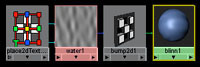

Assistant Online - Maya/How Tos/Rendering/Ripple
Alias|Wavefront / Assistant Online / Maya / How Tos / Rendering / Ripple
HOW TO MAKE WATER RIPPLE
by Steve Christov
Maya Complete
Rendering
In this lesson you will learn
how to create ripples on
water that appear to cross
over and float through each
other.
This will be done by using
multiple water textures that
will be layered to provide
information to a bump node
to produce the ripples. You will map the textures to the
colorOffset attribute to layer the ripples onto surface of the
water.
This article is an update for Maya of a previous article "Texture
Mapping Aoffsets" by Erik Noteboom; Alias Assistant, Issue
#14.
STEP ONE
Open the Hypershade
window and Create a Blinn
material node.
Open the Attribute editor window for the Blinn.
● Set the Color to Light Blue.
Map a
●
Water texture to Bump Mapping.
Rename
●
this texture to Ripple.
http://www.aw.sgi.com/assistant_online/entertain/maya/how_tos/rendering/ripple/ (1 of 5) [3/7/2000 14:49:46]

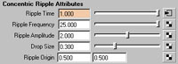


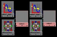

Assistant Online - Maya/How Tos/Rendering/Ripple
STEP TWO
Create a NURBS Plane.
Scale it out so that it covers
the grid in your perspective
window.
Add and Position a
Directional light so that it is
illuminating the plane.
Assign the Blinn to the
Plane.
STEP THREE
In the Attribute Editor for the
Ripple set the following:
Wave Amplitude
●
to 0.0
Ripple Amplitude
●
to
2.0
Spread Rate
●
to 0.5
This will be your main water texture that will have other water
textures mapped into the Color Offset attribute.
STEP FOUR
To animate the ripples, you will need to keyframe the Ripple
Time attribute.
Make sure your Timeslider is at 1. In the Attribute editor for your Ripple texture, set the Ripple Time to 0 and using the RMB set a key for it. Move your Time Slider to 40 and key the Ripple Time at 1.
STEP FIVE
You will now duplicate the
Ripple texture with the
animation.
With the Ripple node in
the Hypershade selected,
go to Edit -> Duplicate ->
Shading Network.
Rename this texture node Ripple1. This will create a new water
node without any connections to the shading network.
http://www.aw.sgi.com/assistant_online/entertain/maya/how_tos/rendering/ripple/ (2 of 5) [3/7/2000 14:49:46]

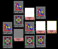

Assistant Online - Maya/How Tos/Rendering/Ripple
STEP SIX
In the Attribute editor for
Ripple1, change the Ripple
Origin to 0.2 and 0.3. Finally
with your MMB, drag the
Ripple1 onto Ripple, and
connect to Color Offset from
the pop-up menu. Notice the
updated water texture in the
Hypershade.
At this point you will notice that the original water texture
becomes white. This is because the color offset channel is used
to add color. By mapping a texture to it you are actually adding
more color to it thus resulting in a white. This will still work with
this example because the information for the bump is there
even though you cannot see it.
NOTE: To see the changes you are making in the Hypershade
on the original water texture, you can remap the colors of the
original water texture with a ramp.
STEP SEVEN
Repeat the above steps to
produce two more water
textures. Rename these
Ripple2 and Ripple3.
Connect Ripple2 to
Ripple1's colorOffset.
Connect Ripple3 to
Ripple2's colorOffset.
Click here to view larger image
For the Ripple2 change
the Ripple Origin to 0.4 and 0.4.
For the Ripple3 texture change the Ripple Origin to 0.3 and 0.5.
http://www.aw.sgi.com/assistant_online/entertain/maya/how_tos/rendering/ripple/ (3 of 5) [3/7/2000 14:49:46]


Assistant Online - Maya/How Tos/Rendering/Ripple
STEP EIGHT
In the Hypershade window,
select the Ripple3 texture.
Select Window ->
Animation Editors ->
Graph Editor.
Press W on the keyboard to
select the Move tool. Click
on the curve to select it.
Click here to view larger image
Hold down the Shift key,
Move the curve to the right so that the end Keyframe is set to around 70.
Repeat for the Ripple2 and Ripple1, setting their end keys at 60
and 55 respectively.
STEP NINE
Render the Scene.
You will notice in your render
that only the Ripple node is
rendered while the others do
not render out. The reason for
this is that the Bump node
uses Alpha information which
is not provided because you
have only been mapping color information from the previous
nodes. You will need to use color information to provide the
bump information.
To do this, Create a
Luminance Node in the
Hypershade under the
Utilities menu.
Highlight the connection
between Ripple and the
Bump Node and press
Delete.
Click here to view larger image
Drag Ripple onto the
Luminance node, the connection editor will open. Connect
Ripple.outColor to Luminance.value.
Drag Luminance on to the Bump Node, and Connect
Luminance.outValue to Bump.bumpValue.
http://www.aw.sgi.com/assistant_online/entertain/maya/how_tos/rendering/ripple/ (4 of 5) [3/7/2000 14:49:46]


Assistant Online - Maya/How Tos/Rendering/Ripple
CONCLUSION
Test Render your scene at
a few diffrent frames. You
should now see ripples on
the surface.
Mapping textures to the
colorOffset of a texture
offers a way to layer
textures that will ultimately
be used as a bump map. Keep in mind that you will need to
use a luminance node to achieve this result.
Another approach to this is instead of connecting Outcolor to
colorOffset, connect outAlpha to the Alpha Offset for each texture thus keeping Alpha information intact which can
connect directly to the Bump Node therefore eliminating the
need for the Luminance node.
Download ripple.ma. [~ 5kb]
Use of this file confirms your agreement to the Terms and Conditions
set out on the Terms and Conditions page.
http://www.aw.sgi.com/assistant_online/entertain/maya/how_tos/rendering/ripple/ (5 of 5) [3/7/2000 14:49:46]
http://www.aw.sgi.com/assistant_online/entertain/maya/how_tos/rendering/ripple/img/six.jpg http://www.aw.sgi.com/assistant_online/entertain/maya/how_tos/rendering/ripple/img/six.jpg [3/7/2000 14:49:53]
http://www.aw.sgi.com/assistant_online/entertain/maya/how_tos/rendering/ripple/img/eight.jpg http://www.aw.sgi.com/assistant_online/entertain/maya/how_tos/rendering/ripple/img/eight.jpg [3/7/2000 14:50:02]
http://www.aw.sgi.com/assistant_online/entertain/maya/how_tos/rendering/ripple/img/nine_2.jpg http://www.aw.sgi.com/assistant_online/entertain/maya/how_tos/rendering/ripple/img/nine_2.jpg [3/7/2000 14:50:06]


Assistant Online - Maya/How Tos/Rendering/Shading Networks
Alias|Wavefront / Assistant Online / Maya / How Tos / Rendering / Shading Networks
HOW SHADING NETWORKS OPERATE
by Robert Magee
Maya: Base
Rendering
Maya's Shading networks allow you to build up a shader using
various nodes. These nodes connect together to help
determine the final look of the shader when it is applied to a
surface.
The descriptions in the Maya shader library are a great place to
learn more about how different nodes come together to form a
network. You can use these descriptions to help you work with
the pre-built shaders and to analyze them for learning
purposes.
Material Nodes
Material nodes contain all the information that affects the
overall shading of the network. Some of the common material
types include:
Lambert
●
Phong
●
PhongE
●
Blinn
●
There are attributes associated with these nodes that allow you
to determine Common material attributes such as reflectivity,
transparency and color. You can also determine the way in
which the surface reacts to light using the Specular shading
attributes.
http://www.aw.sgi.com/assistant_online/entertain/maya/how_tos/rendering/shader_ref/ (1 of 3) [3/7/2000 14:50:14]


Assistant Online - Maya/How Tos/Rendering/Shading Networks
Texture Maps
In Maya, every attribute can be mapped to create more
dynamic results. Some of the common mapping types include:
Color maps
●
Bump maps
●
Transparency maps
●
Specular maps
●
In each of these mapping types, you will see that the normal
value associated with an attribute is replaced by the values
found in the map. In some cases, there are RGB values
associated with the color of a map and in others cases it is the
alpha information which is used in the map.
Placement Nodes
When you create a texture map, it needs to be created with
some relationship to the surfaces on which it is mapped. You
can choose a 2D or 3D mapping to achieve the final look.
A 2D placement uses the surface's UV coordinates to place
the texture. The texture can then be adjusted to fit the UV
space accordingly.
A 3D placement uses an external icon to determine the
position of the texture in 3D space. You can position, scale and
rotate the icon to get the mapping that you want. In fact, for
many of the library shaders, you would want to adjust the icon
to suit your own objects.
If you want to animate your object, then the placement node
must be parented to the object or the texture will swim on the
surface. If you have a deforming surface then you will have to
convert the 3D texture into a 2D texture which works better on
the surface as it deforms.
Utility Nodes
Maya also includes utility nodes that can add important
functionality to a shading network. For instance a BlendColors
node can let you combine two textures. The Sampler Info node
can get information from surfaces during the rendering process
then use that information to affect the network.
In the shader library, you will find some examples of utility
nodes at work.
http://www.aw.sgi.com/assistant_online/entertain/maya/how_tos/rendering/shader_ref/ (2 of 3) [3/7/2000 14:50:14]


Assistant Online - Maya/How Tos/Rendering/Shading Networks
Conclusion
This short synopsis of how shading networks operate is
designed to help you make best use of the shader library.
Reviewing how other people build shaders is one of the best
ways to begin creating your own.
Your use of this file confirms your agreement to the
Terms and Conditions set out in the Terms and Conditions page.
http://www.aw.sgi.com/assistant_online/entertain/maya/how_tos/rendering/shader_ref/ (3 of 3) [3/7/2000 14:50:14]


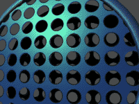


Assistant Online - Maya/How Tos/Rendering/Share Texture Nodes
Alias|Wavefront / Assistant Online / Maya / How Tos / Rendering / Share Texture Nodes
HOW TO SHARE
by Terry Stoeger
TEXTURE NODES
MAYA Complete
Rendering
In this lesson, you will learn
how to use the same ramp
texture node to define the
transparency, specular color
and bump maps.
The advantage of using the
same texture node for all
three is the ease of making
Download Movie [~240 Kb]
changes: you would only have to make changes to one ramp
instead of three.
For this example you will make a shading network that creates
a shiny, perforated surface.
STEP ONE
In the Hypershade menu select Create, and add the following:
Materials
●
-> Blinn Surface Material (With Shading
Group turned on)
Textures
●
-> 2D -> Ramp texture (Include Placement
turned on)
Utilities
●
-> General -> Reverse
Utilities
●
-> Color -> Clamp node.
http://www.aw.sgi.com/assistant_online/entertain/maya/how_tos/rendering/sharing_node/ (1 of 4) [3/7/2000 14:50:23]

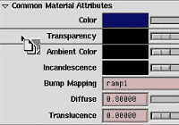


Assistant Online - Maya/How Tos/Rendering/Share Texture Nodes
STEP TWO
Begin by double clicking the
ramp texture to open the
attribute editor.
Change the Type to
Circular Ramp.
Set the ramp colors to black
and white and slide them
closer together.
Select the place2dTexture
tab and change the Repeat UV to 5 and 5.
STEP THREE
Double click on the Blinn
Shading Group to open the
Attribute Editor.
Change the Color to a dark
blue.
You will now map the ramp
to the Transparency. Drag and Drop with MMB the ramp
texture to the Transparency slider of the Blinn Shading
Group.
STEP FOUR
If you were to map the ramp directly to the specular color, the transparent areas would have highlights instead of the opaque
areas. This is because white is treated as transparent and black
as opaque. To solve this, you will connect the reverse utility
node to the ramp before mapping to the specular color.
In the Hypershade, Drag and Drop with MMB the ramp onto the
reverse node. This will open the Connection Editor with the
ramp in the Outputs column and the Reverse node in the
inputs column.
In the left column, click on Out Color and then click on Input in the right column. This connects the Ramp node's Out Color to the Reverse node's Input.
http://www.aw.sgi.com/assistant_online/entertain/maya/how_tos/rendering/sharing_node/ (2 of 4) [3/7/2000 14:50:23]
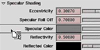


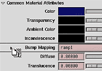
Assistant Online - Maya/How Tos/Rendering/Share Texture Nodes
STEP FIVE
If you map this new reverse node directly to the specular
color, you will have no control over its color. This can be solved
by inserting the clamp utility node.
Drag and Drop with MMB the reverse node onto the clamp
node. This will open the Connection Editor with the reverse
node in the Outputs column and the clamp node in the inputs
column.
In the left column, click on Output and then click on Input in the right column. This connects the reverse nodes Output to the clamp nodes Input.
STEP SIX
Double click on the Blinn
Shading Group to open the
Attribute Editor.
You will now map the clamp
to the Specular Color.
Drag and Drop with MMB the clamp utility node onto the
Specular Color slider of the Blinn Shading Group. This
connects the Clamp Output to the Blinn's Specular Color.
STEP SEVEN
The clamp node can now be used to control the intensity and
color of the specular highlight.
Double click on the clamp node to open the Attribute Editor. In
the Clamp Color Attributes section, enter .75 in all three
channels for Max. This will give you a 75% gray as the specular
color. As you enter .75 in the channels, watch the Shading
group in the Hypershade. You will see first red being added ,
then green, then blue. This is the order of the min, max and
input channels from left to right X-Y-Z = R-G-B . For
example: If you want the specular color to be blue, lower the
number in the red and green channels.
STEP EIGHT
Finally, the Ramp texture
will also be used for a Bump
Mapping.
Drag and Drop with MMB
the Ramp texture onto the
Bump Mapping attribute in
the Blinn attribute editor.
http://www.aw.sgi.com/assistant_online/entertain/maya/how_tos/rendering/sharing_node/ (3 of 4) [3/7/2000 14:50:23]
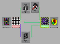


Assistant Online - Maya/How Tos/Rendering/Share Texture Nodes
CONCLUSION
You have now created a
shading network that uses
one texture for
Transparency, Specular
Color, and Bump Mapping.
Any change to the texture
or its placement, will be
reflected in all three
channels. This will also
minimize confusion and
improve rendering performance.
Your use of this file confirms your agreement to the
Terms and Conditions set out in the Terms and Conditions page.
http://www.aw.sgi.com/assistant_online/entertain/maya/how_tos/rendering/sharing_node/ (4 of 4) [3/7/2000 14:50:23]


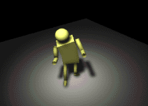


Assistant Online - Maya/How Tos/Rendering/Soft Spotlight
Alias|Wavefront / Assistant Online / Maya / How Tos / Rendering / Soft Spotlight
HOW TO CREATE
by Haskell Friedman
A SOFT SPOT LIGHT
MAYA Complete
Rendering
In this lesson, you will
learn how to create a spot
light with soft lighting and
shadows. This will involve
the setting of several light
attributes such as decay,
intensity and penumbra
angle as well as the use of
Default Lighting [~432kb]
depth map shadows.
By default, Maya's spot
lights create strong sharp lighting. In this lesson, you will learn
how to soften the effect of the light by adjusting various light
attributes. Throughout this example, you will be shown how
changing each attribute affects the look of the scene. At the
end, you will learn how to use depth map shadows to further
enhance the soft lighting effect.
STEP ONE
Create a primitive NURBS
plane to act as a floor
surface. Set Scale X,
Scale Y,and Scale Z to
24.0, so that the plane
covers the perspective
grid. Rename the surface
floor.
If you would like to preview the scene using interactive
hardware lighting, set the surface's Patch U and V to 16.
Place a character into the scene. This lesson uses Primitive
man from Lesson 15 in the Learning Maya book. Place the
character at the origin (0, 0, 0) and set the character's height to
about 6 units.
http://www.aw.sgi.com/assistant_online/entertain/maya/how_tos/rendering/soft_spot_light/ (1 of 5) [3/7/2000 14:50:42]

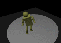

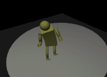

Assistant Online - Maya/How Tos/Rendering/Soft Spotlight
STEP TWO
Create a spotlight then
rename it softSpotLight.
Use the Show
Manipulator tool to place
the eye-point manipulator
above the character at
roughly a 45 degree angle.
Place the look-at
manipulator at the origin.
Create an ambient light to provide fill lighting for the scene. Edit
the Intensity to a value of 0.25 and the Ambient Shade to 0.0.
STEP THREE
In the Render Globals, set
the Presets to Preview
Quality in the Anti-aliasing
Quality tab.
Test render the scene to
preview the lighting.
Looking at the image, you
will notice that the edge of the light, which is called the umbra,
is very sharp. In this lesson, you will soften this edge. First you
will tweak the color and angle of the light.
STEP FOUR
Open the Attribute editor
for softSpotLightShape.
Click on the Color swatch
and set the HSV to 44.0,
0.06, 1.0. This creates a
slightly off-white color.
Now set the Cone Angle
to around 45 degrees.
Re-render the scene. Now the light's umbra is larger and covers
more of the floor surface.
http://www.aw.sgi.com/assistant_online/entertain/maya/how_tos/rendering/soft_spot_light/ (2 of 5) [3/7/2000 14:50:42]

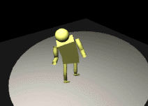


Assistant Online - Maya/How Tos/Rendering/Soft Spotlight
STEP FIVE
You will now add Decay to
your light. This means that
the intensity of the light will
decrease as the distance
away from the source
increases.
To add decay to the
scene, set the light's Decay Rate to Quadratic.
Re-render the scene. The scene has suddenly become very
dark. This is because the intensity of the light is not strong
enough for this decay setting.
STEP SIX
To compensate for the
new decay rate you will
have to increase the
amount of light in your
scene. Set the spot light's
Intensity to 500.
Re-render the scene. Now
your scene has more than enough illumination to compensate
for the decay. In fact, the scene should be a little over-exposed
since you will be further softening the light in the next step.
STEP SEVEN
Earlier you noted that the
light's umbra is too sharp.
To soften it, you will need
to set the light's Penumbra
angle and Dropoff. The
Penumbra angle defines a
ring around the light's
edge where the light will
fade more quickly. The Dropoff will cause the light intensity to
decrease from the center of the spot to the umbra.
Set the Penumbra Angle to 5.0 and the Dropoff to 25.0.
Re-render the scene. You should now see a softening effect
that is a combination of the Penumbra, Dropoff and Decay.
http://www.aw.sgi.com/assistant_online/entertain/maya/how_tos/rendering/soft_spot_light/ (3 of 5) [3/7/2000 14:50:42]


Assistant Online - Maya/How Tos/Rendering/Soft Spotlight
STEP EIGHT
Now that you have soft
lighting you will want soft
shadows. You will use
Depth map shadows to
achieve the desired effect.
In the Attribute Editor for
your softSpotLight, open
the Shadows section. Under Depth Map Shadow Attributes,
turn Use Depth Map Shadows to On.
Re-render your scene. With the default settings, the shadow
appears sharp and pixelated compared to the light itself.
STEP NINE
To fix the shadow, you will
reduce the resolution of
the depth map and apply a
filter setting that will blur
the effect of the shadow.
You are going to use a
very low resolution depth
map so that it appears
softer. If you were to
increase the resolution of
the depth map, the shadow would appear sharper and you
would require a higher filter setting to soften the shadow.
In the Attribute editor, set the Dmap Filter Size to 4 and the Dmap Resolution to 256.
Render your scene. Now the shadows match correctly with the
type of lighting being produced. This completes the soft light
effect.
Note: You can increase the Dmap Filter Size for higher quality
shadows but keep in mind that the higher the filter size the
longer it will take your scene to render.
CONCLUSION
You now know how to soften a spotlight by combining,
decay, dropoff, penumbra and depth map shadows. Be sure
to remember that the attribute values used in this lesson
have been chosen because of the size of the scene. To use
similar lighting in your work, you may have to increase or
decrease the attribute values depending on the positioning of
your lights and the size of your scene.
http://www.aw.sgi.com/assistant_online/entertain/maya/how_tos/rendering/soft_spot_light/ (4 of 5) [3/7/2000 14:50:42]


Assistant Online - Maya/How Tos/Rendering/Soft Spotlight
Your use of this file confirms your agreement to the
Terms and Conditions set out in the Terms and Conditions page.
http://www.aw.sgi.com/assistant_online/entertain/maya/how_tos/rendering/soft_spot_light/ (5 of 5) [3/7/2000 14:50:42]


Assistant Online - Maya/How Tos/Rendering/Toon Shader
Alias|Wavefront / Assistant Online / Maya / How Tos / Rendering / Toon Shader
HOW TO MAKE A
by Tom Kluyskens
CARTOON SHADER
MAYA Complete
Rendering
In this lesson, you will
learn how to create a
cartoon shader. By
combining several utility
nodes to remap a Blinn
material node using a
Ramp, you will define the
cartoonish look of the
shader.
Play Movie [~485kb]
This lesson will help you
better understand how you can create custom shading
networks using the Connection editor and utility nodes.
STEP ONE
In the Hypershade, select Create -> Create Render Node..
and create the following rendering nodes:
Material nodes:
Blinn (no Shading Group),
Surface Shader (with Shading Group)
Texture nodes:
Ramp (no Texture Placement, Normal)
Utility nodes:
Sampler Info
Clamp
Condition
The Blinn material node will be used to catch highlights on the
objects. Leave the color grey. The greyscale blinn shading
(white = highlights) will be transformed into the cartoon shader
effect by remapping the grey values into a sequence of colors
using a ramp. The Sampler info node will be used to put a line
at the objects' border.
http://www.aw.sgi.com/assistant_online/entertain/maya/how_tos/rendering/toon_shader/ (1 of 4) [3/7/2000 14:50:55]


Assistant Online - Maya/How Tos/Rendering/Toon Shader
STEP TWO
In the Hypershade with the MMB, drag the Blinn node over the
Clamp node to open the Connection Editor. Connect the Blinn
node's Out Color to the Clamp node's Input.
The Clamp node is going to reduce all greyscale values to
values less than or equal to 1. The clamp cuts off all highlights
that have a greyscale value greater than 1 (superwhite).
Open the Attribute Editor for the Clamp node, and set the left
Max field to 1. The left field represents the Red channel
(middle = Green, right = Blue), but because grey is an equal
mix of R G and B, you only need one channel (this lesson
chooses R). Min should be set to 0.
STEP THREE
The same way, connect the Output R of the Clamp node to the
V Coord of the Ramp node, using the Connection Editor.
Make sure that your Ramp is a V Type ramp. The color output
of the ramp is now going to be the color in the ramp that
corresponds to the greyscale value (0 <= clamp Color R Output
<= 1) of the input. This technique is called remapping.
STEP FOUR
Connect the Ramp node's Out Color to the Color1 of the Condition node. Also connect the Facing Ratio of the Sampler info node to the First Term of the Condition node.
The Facing Ratio, is the degree to which a point on a surface is
facing towards the camera. If the point is located on a part of
the surface that is facing 90 degrees away from the camera
(typically the border of a sphere), the Facing Ratio is 0. If the
angle between the surface normal and the camera ray is 0, the
Facing Ratio is 1. Check your online Maya manuals for more
info.
STEP FIVE
Open the Attribute Editor for the Surface shader material.
Select Add -> Add Attributes... and add following attributes (float, scalar):
LineThickness : Min 0, Max 1, Default .2
LineR
LineG
LineB
These are the user-definable border thickness and color.
http://www.aw.sgi.com/assistant_online/entertain/maya/how_tos/rendering/toon_shader/ (2 of 4) [3/7/2000 14:50:55]


Assistant Online - Maya/How Tos/Rendering/Toon Shader
STEP SIX
Connect the Line
Diagram of final dependency graph
Thickness and LineR G B
of the Surface shader
node to the Second Term and Color2 R G B of the Condition node.
Set the Condition Operation to Greater Than.
If the Facing Ratio (first term of the condition) is smaller than
the line thickness (second term), the condition output will be
Color2 (line color set in surface shader), else it will be Color1
(ramp-blinn color).
Connect the Condition node's Out Color to the Surface
shader node's Out Color.
STEP SEVEN
Adjust your Ramp to use the colors that you want. Cartoon
shaders normally may be designed to use no interpolation
between the ramp colors in order to create hard uniform color
zone edges. Shown below is a sample ramp and how the final
shader appears. Here are some examples of how different
positions, color zones and interpolation affect the final result.
Other edits you can make include the following:
Adjust line thickness and color in the attributes of the
●
surface shader.
Adjust your blinn parameters to have different kinds of
●
highlights.
You can even put a bump map on the blinn. This
●
technique was used on the worm in the animation.
You can use another material (instead of blinn) to get
●
other kinds of highlight.
You can now assign the shader to your objects.
http://www.aw.sgi.com/assistant_online/entertain/maya/how_tos/rendering/toon_shader/ (3 of 4) [3/7/2000 14:50:55]


Assistant Online - Maya/How Tos/Rendering/Toon Shader
CONCLUSION
This lesson taught you how to build a cartoon shader as well as
how to work with several utility nodes to build a complex
shading network.
Thanks to Michele Borghi and Duncan Brinsmead for the
original design of the cartoon shader.
Your use of this file confirms your agreement to the
Terms and Conditions set out in the Terms and Conditions page.
http://www.aw.sgi.com/assistant_online/entertain/maya/how_tos/rendering/toon_shader/ (4 of 4) [3/7/2000 14:50:55]
http://www.aw.sgi.com/assistant_online/entertain/maya/how_tos/rendering/toon_shader/img/cartoon_depend_lg.gif http://www.aw.sgi.com/assistant_online/entertain/maya/how_tos/rendering/toon_shader/img/cartoon_depend_lg.gif [3/7/2000 14:50:59]


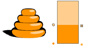

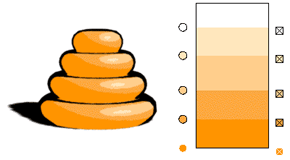
Assistant Online - Maya/How_Tos/Rendering/Toon Shaders/Ramp Examples
Alias|Wavefront / Assistant Online / Maya / How Tos / Rendering / Ramp Examples
CARTOON SHADER: Ramp examples
Shown below are some sample ramps that explore how the
positions, number of color zones and ramp interpolation affect
the final result:
Example1: 2 colors, no interpolation
Example2: 3 colors, no interpolation
Example3: 5 colors, no interpolation
http://www.aw.sgi.com/assistant_online/entertain/maya/how_tos/rendering/toon_shader/ramp.html (1 of 2) [3/7/2000 14:51:17]
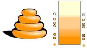
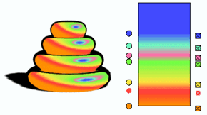


Assistant Online - Maya/How_Tos/Rendering/Toon Shaders/Ramp Examples
Example4: 2 colors, smooth interpolation
Example5: 4 colors with transition zones, smooth interpolation
Example6: 5 rainbow colors, linear interpolation
Your use of this file confirms your agreement to the
Terms and Conditions set out in the Terms and Conditions page.
http://www.aw.sgi.com/assistant_online/entertain/maya/how_tos/rendering/toon_shader/ramp.html (2 of 2) [3/7/2000 14:51:17]


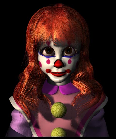
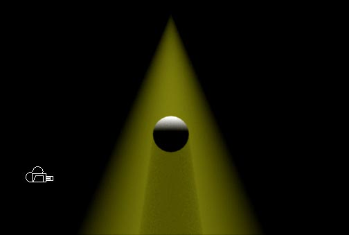
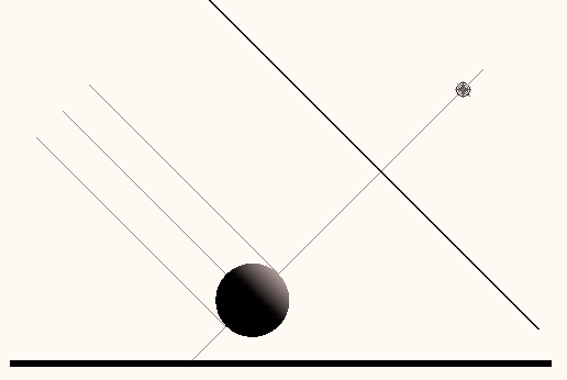
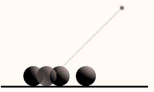
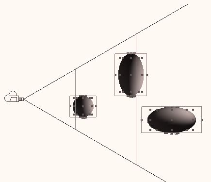
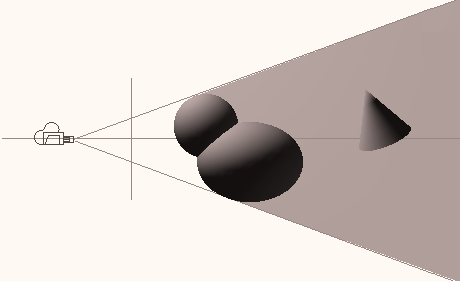
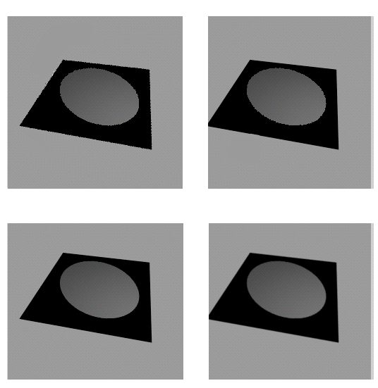
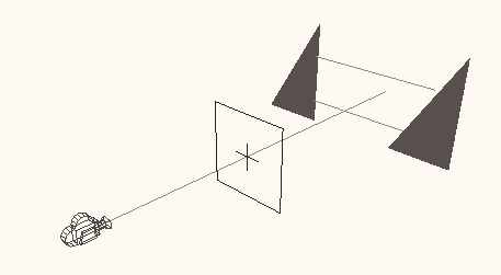
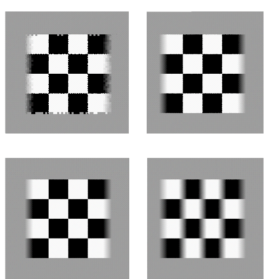
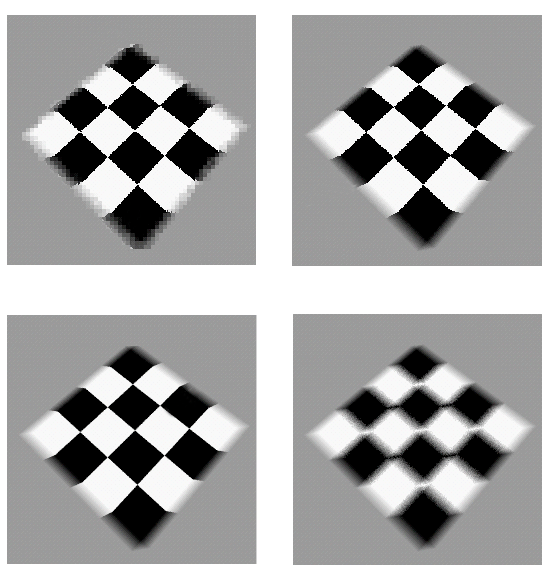
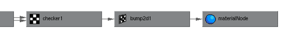
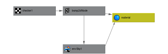
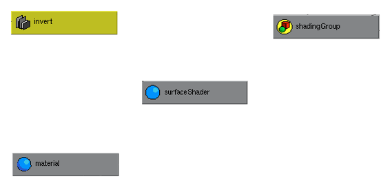


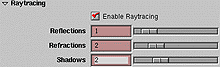
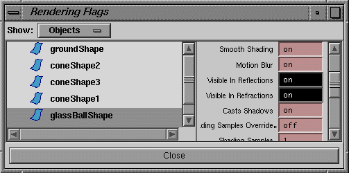
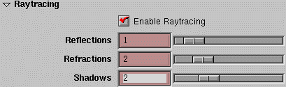


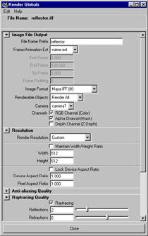
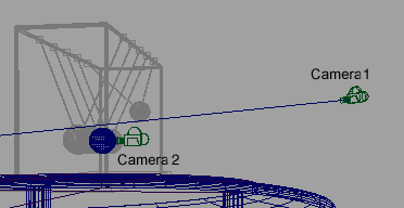

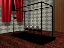
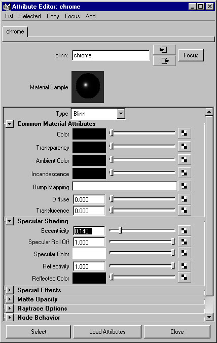
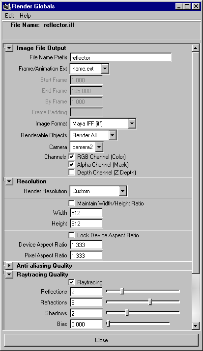
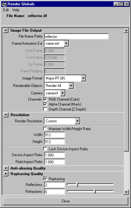


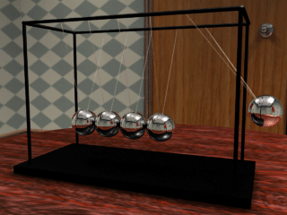

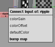
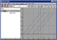
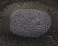
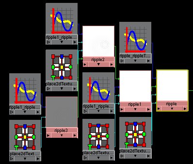

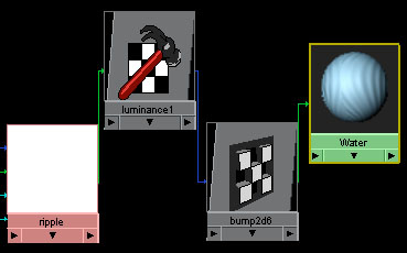


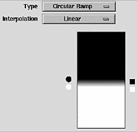


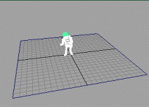
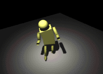


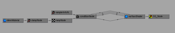

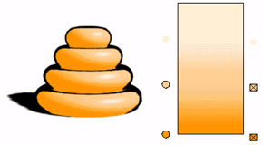