Figure 2.22 Instant Messages
{ 2.2.3. Media Gateway Control Protocols
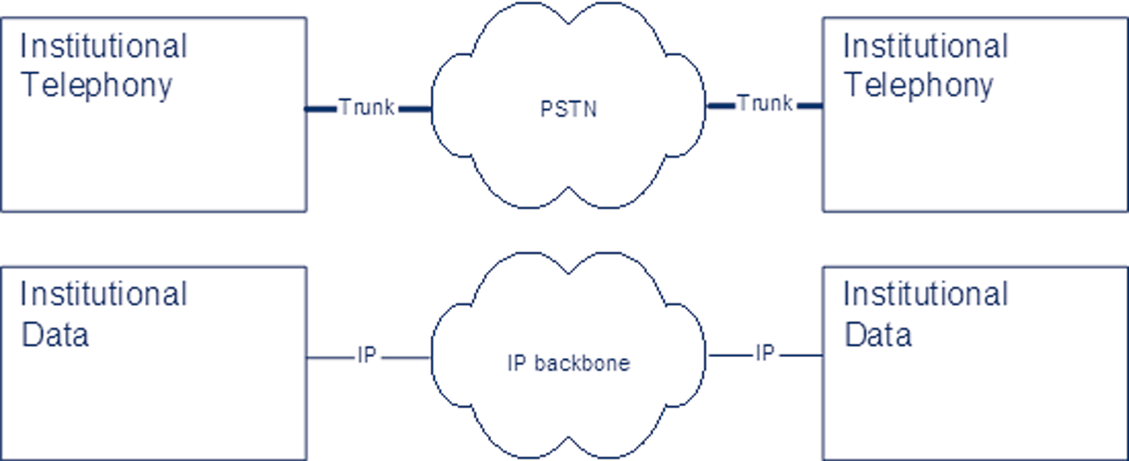
In a traditional telephone network, the infrastructure consists of large telephone switches which interconnect with each other to create the backbone network and which also connect to customer equipment (PBXs, telephones).While the internal network today is based upon digital communication, links to customers may be either analogue (PSTN) or digital (ISDN).The links to customers are shared between call signalling (for dialling, invocation of supplementary services, etc.) and carriage of voice/data. In the backbone, dedicated (virtual) links interconnecting switches are reserved for call signalling (de-facto creation of a dedicated network of its own) whereas voice/data traffic is carried on separate links.The Signalling System No. 7 (SS7) or P.47
[IP Telephony Cookbook] / Technological Background
variants of it are used as the call signalling protocol between switches; this protocol is used to route voice/data channels across the backbone network by instructing each switch on the way which incoming ‘line’ is to be forwarded to which outgoing ‘line’ and which other processing (such as simple voice compression, in-band signalling detection to customer premise equipment, etc.) is to be applied.Voice/data channels themselves are plain bit pipes identified by roughly a trunk and line identifier at each switch.
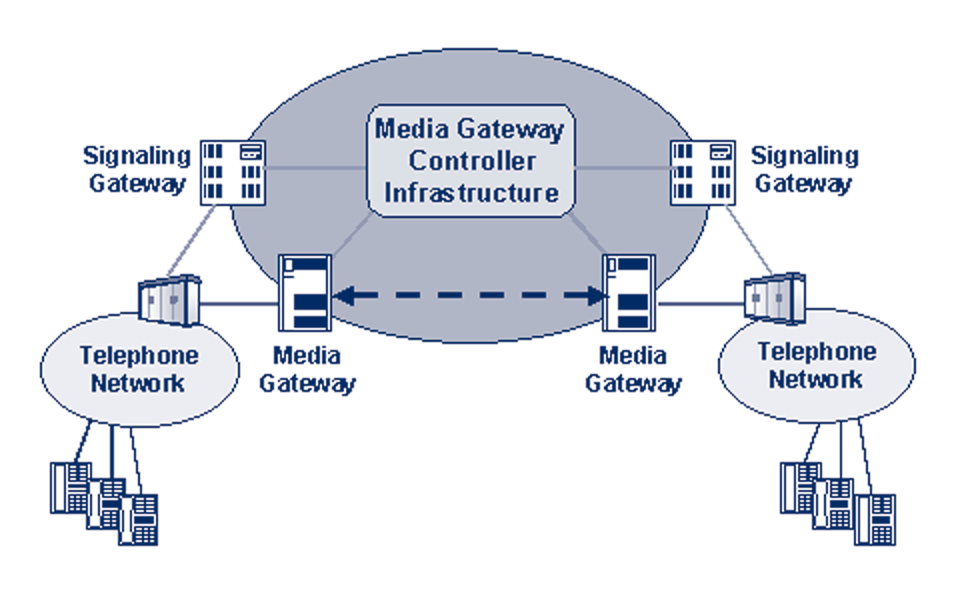
Figure 2.23 Application scenario for Media Gateway Control Protocols A similar construction is now considered by a number of telecom companies for IP-based backbone networks that may successively replace parts of their overall switched-network infrastructure, as depicted in Figure 3.7. Instead of voice switches, IP routers are used to build up a backbone network which employs IP routing, possibly MPLS, and, most likely, some explicit form of QoS support to carry voice and data packets from any point in the network to any other. In contrast to voice switches, this does not require explicit configuration of the individual routers per voice connection. Instead, only the entry and exit points need to be configured with each others' addresses, so that they know where to send their voice/data packets.Two types of gateways are used at the edges of the IP network to connect to the conventional telephone network: signalling gateways to convert SS7 signalling into IP-based call control (which may make use of H.323 or SIP or simply provide a transport to carry SS7 signalling in IP packets [SIGTRAN]) and media gateways that perform voice transcoding. Some central entity (or more probably, a number of co-operating entities) forms the intelligent core of the backbone, the Media Gateway Controller(s).They interpret call signalling and decide how to route calls and they provide supplementary services, etc. Having decided on how a call is to be established, they inform the (largely passive and ‘dumb’) media gateways at the edges (ingress and egress gateways) how and where to transmit the voice packets.The Media Gateway Controllers also re-configure the gateways in case of any changes in the call, invocation of supplementary services, etc.The media gateways may be capable of detecting invocation of control features in the media channel (e.g., through DTMF tones) and notify the Media Gateway Controller(s), which then initiate the appropriate actions.
A number of protocols have been defined for communication between Media Gateway Controllers and media gateways. Initial versions were developed by multiple camps, some of which merged to create the Media Gateway Control Protocol (MGCP), the only one of the proprietary protocols that is documented as an Informational RFC (RFC 2705). An effort was launched to make the two remaining camps cooperate and develop a single protocol to be standardised, which resulted in work groups in the ITU-T (rooted in Study Group 16, Q.14) and P.48
[IP Telephony Cookbook] / Technological Background
in the IETF (Media Gateway Control, MEGACO WG).The protocol being jointly developed is referred to as H.248 in the ITU-T and as MEGACO in the IETF.
One particular protocol extension currently discussed in the IETF is the definition of a protocol for communication with an IP telephone at the customer premises that fits seamlessly with the Media Gateway Control architecture. Such a telephone would be a rather simple entity, essentially capable of transmitting and receiving events and reacting to them, while the call services are provided directly by the network infrastructure.
{ 2.2.4 Proprietary signalling protocols
Today nearly every vendor that offers VoIP products uses his own VoIP protocol, e.g., Cisco's Skinny or Siemens's CorNet.They were invented by the vendors to be able to provide more specific supplementary services in the Voice over IP world, in order to offer customers all the features they already know from their classic PBX.The enterprise solutions usually feature such proprietary protocols at the cure and provide minimalist support for standardised protocols (until now usually H.323) with only basic call functionality.
Giving detailed information about those protocols is out of the scope of this document and is usually difficult to provide because most protocols are not publicly available.
{ 2.2.5. Real Time Protocol (RTP) and Real Time Control Protocol (RTCP) RTP and RTCP are the transport protocols used for IP Telephony media streams. Both of them were defined in RFC1889: the former as a protocol to carry data that has real-time properties, the latter to monitor the quality of service and to convey information about the participants in ongoing session.The services provided by the RTP protocol are:
- identification of the carried information (audio and video codecs);
- checking packet in-order delivery and, if necessary, re-ordering the out-of-sequence blocks;
- transport of the coder/decoder synchronisation information;
- monitoring of the information delivery.
The RTP protocol uses the underlying User Datagram Protocol (UDP) to manage multiple connections between two entities and to check for data integrity (checksum). An important point to stress is that RTP neither provides any means to have a guaranteed QoS nor assumes the underlying network delivers ordered packets.
The RTCP protocol uses the same protocols as RTP to periodically send control packets to all session participants. Every RTP channel using port number N has its own RTCP protocol channel with port number equal to N+1.The services provided by the RTCP are:
- giving a feedback on the data quality distribution, feedback used to keep control of the active codecs;
- transporting a constant identifier for the RTP source (CNAME), used by the video data;
- advertising the number of session participants which is used to adjust the RTP data transmission rate;
- carrying session control information used to identify the session participants.
P.49
[IP Telephony Cookbook] / Technological Background
The next two subsections describe the RTP and RTCP header and the different types of packets that the two protocols use.
{ 2.2.5.1 RTP header
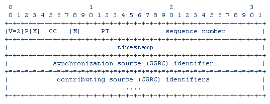
Figure 2.24 shows the RTP header.The first twelve bytes are present in all of the RTP packets.
The last bytes, containing the CSRC (Contributing SouRCe) identifiers list, is present only when a mixer is crossed (mixer refers to a system which receives two or more RTP flows, combines them and forwards the resulting flow).
Figure 2.24 RTP header
The header fields are here detailed:
- version (V - 2 bits) contains the RTP protocol version;
- padding (P - 1 bit), if set to 1, then the packet contains one or more additional bytes after the data field;
- extension (X - 1 bit), if set to 1, then the header is followed by an extension;
- CSRC count (CC - 4 bits) contains the CSRC identifier number which follows the header;
- marker (M - 1 bit) is the application available field;
- payload type (PT - 7 bits) identifies the data field format of the RTP packet and determines its interpretation by the application;
- sequence number (16 bits) value incremented by one for each RTP packet sent, is used by the receiver to detect losses and to determine the right sequence;
- RTP timestamp (32 bits) is the sampling time of the first RTP byte, used for synchronisation and jitter calculation;
- SSRC ID (32 bits) identifies the synchronisation source, chosen randomly within a RTP
session;
- CSRC ID list (from 0 to 15*32 bits) is an optional field identifying the sources which contribute to the data in the packet.The number of the CSRC IDs is written in the CSRC
count field.
{ 2.2.5.2 RTCP packet-types and format
In order to transport the session control information, the RTCP foresees a number of packet-types:
- SR, Sender Report, to carry the information sent by the transmitters, to give notice to the other participants on the control information they should receive (number of bytes, number of packets, etc.);
P.50
[IP Telephony Cookbook] / Technological Background
- RR, Receiver Report, to carry the statistics of the session participants which are not active transmitters;
- SDES, Source DESscription, to carry the session description (including the CNAME
identifier);
- BYE, to notify the intention of leaving the session;
- AAP, to carry application specific functions, used by experimental use of new applications.
Every RTCP packet begins with a fixed part similar to the one of the RTP ones, and this part is then followed by structural elements of variable length. More than one RTCP packet may be linked together to build a COMPOUND PACKET. Moreover, in order to maximise the statistics resolution, the SR and the RR packet-types are to be sent more often than the other packet-types.
P.51
[IP Telephony Cookbook] / IP Telephony Scenarios
IP Telephony Scenarios >