Setting geometry appearances
The Java 3D Appearance class enables you to set rendering attributes for the geometric primitives in your scene—at startup, during scenegraph creation, or dynamically at runtime. After reading this chapter, you should be able to dynamically modify the appearance of the geometry within your scenegraph.
Java 3D contains a host of classes to specify the rendering attributes for geometric primitives, such as color, texture, back-face removal, and so on. Java 3D defines “has-a” relationships between the classes that control overall rendering appearance. For example, an Appearance has a Material class, a PolygonAttributes class, a RenderingAttributes class, and so on. This is one of the best-designed areas of Java 3D; with a little experience you can quickly learn to navigate the various classes that, when combined, specify object appearance. Compared with learning the plethora of separate OpenGL methods to specify appearance, the OO nature of the Java 3D design pays dividends.
An instance of an Appearance object is associated with each Shape3D geometric object in the scenegraph. The Appearance object defines rendering state information that must be applied to the rendering pipeline before the raw geometry within the Shape3D is rendered.
It is useful to think of the Java 3D renderer traversing through the defined scenegraph; when it encounters TransformGroups, it applies matrix transformations; when it encounters a Shape3D Node, it applies the Shape3D’s Appearance state—all before executing the Shape3D object to generate native graphics API calls.
What follows is an overview of the NodeComponent-derived classes that define a Java 3D rendering state for a Shape3D object. Emphasis is placed on areas of potential confusion or typical problems. Consult the detailed Sun API reference for a method-by-method summary of the classes. I have prefaced each section with a table listing the capability bits that control access to the specific feature being discussed. The tables include references to OpenGL functions where appropriate and useful.
One of the lengthier examples of the book accompanies this chapter: AppearanceTest (illustrated in figure 9.1) allows you to dynamically modify most of the Appearance attributes on a simple scene. I encourage you to examine the code for the example and run it as you work through this chapter—most of the sections will be significantly clarified by this interactive example.
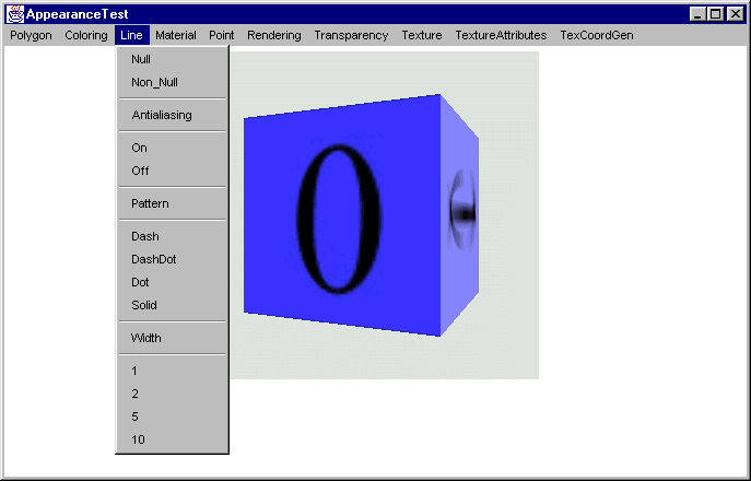
Figure 9.1 The AppearanceTest example application allows Appearance settings to be modified at runtime
java.lang.Object
|
+--javax.media.j3d.SceneGraphObject
|
+--javax.media.j3d.NodeComponent
|
+--javax.media.j3d.Appearance
The Appearance class contains member variables that together define an appearance state for a Shape3D object. A Shape3D object basically contains Geometry and Appearance. The Appearance class itself does not define any of the properties that control Shape3D appearance, but instead packages Appearance subcomponents, such as PolygonAttributes, RenderingAttributes, and so on.
The Appearance class controls access to its member variables through the familiar, but rigorous, process of setting capability bits. That is, the application developer must specify which Appearance member variables will be modified after the Appearance is attached to a live scenegraph. A live scenegraph is one that has either been compiled or has been rendered.
The capability bits that control access to the member variables of the Appearance class are:
Preface the listed items with ALLOW_ and add _READ or _WRITE for read or write access respectively. For example, to allow read/write access to the Material and PolygonAttributes member variables, you would put the following in your code:
Appearance app = new Appearance();
app.setCapability( ALLOW_MATERIAL_READ );
app.setCapability( ALLOW_MATERIAL_WRITE );
app.setCapability( ALLOW_POLYGON_ATTRIBUTES_READ ); app.setCapability( ALLOW_ POLYGON_ATTRIBUTES_WRITE );
NOTE
Four separate calls must be made to the setCapability method—it is not possible to OR together the various capabilities. ORing together capability bits will lead to very unpredictable behavior. Public accessor methods to access the member variable are defined as:
app.setMaterial( new Material() );
app.setPolygonAttributes( new PolygonAttributes() );
PolygonAttributes polyAttribs = app.getPolygonAttributes(); Material material = app.getMaterial();
java.lang.Object
|
+--javax.media.j3d.SceneGraphObject
|
+--javax.media.j3d.NodeComponent
|
+--javax.media.j3d.ColoringAttributes
Table 9.1 Capability bits for the ColoringAttributes class
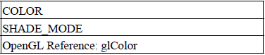
The ColoringAttributes within a Shape3D’s Appearance are used to control the color of a Shape3D if a Material has not also been assigned to the Appearance. If a Material has been assigned, the ColoringAttributes are ignored and the more complex color and lighting information within the Material class are used instead. See table 9.1.
The colors of any vertices within the Shape3D that have per-vertex colors applied are unchanged by the ColoringAttributes.
The next example, from AppearanceTest.java, creates a standard Box and then replaces the LEFT face with a new face created with new geometry and per-vertex colors. When a ColoringAttributes object is assigned to the Appearance for the Box it will set the color for the five original faces but will not effect the LEFT face which has per-vertex colors assigned, as illustrated in figure 9.2.
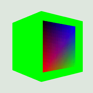
Figure 9.2 A Box primitive with an applied ColoringAttribute. The LEFT face has been removed and replaced with a QuadArray that includes per-vertex colors that are unaffected by the ColoringAttributes
int nScale = 50;
Box box = new Box( nScale,nScale,nScale, Primitive.GENERATE_NORMALS | Primitive.GENERATE_TEXTURE_COORDS, m_Appearance);
Shape3D frontFace = box.getShape( Box.LEFT );
//create a new LEFT face so we can assign per-vertex colors
GeometryArray geometry =
new QuadArray( 4, GeometryArray.COORDINATES | GeometryArray.NORMALS | GeometryArray.COLOR_4 | GeometryArray.TEXTURE_COORDINATE_2 );
nScale = 40;
final float[] verts =
{
// new LEFT face
-1.0f * nScale, -1.0f * nScale, 1.0f * nScale,
-1.0f * nScale, 1.0f * nScale, 1.0f * nScale,
-1.0f * nScale, 1.0f * nScale, -1.0f * nScale,
-1.0f * nScale, -1.0f * nScale, -1.0f * nScale
};
final float[] colors =
{
// left face
1,0,0,0,
0,1,0,0.2f,
0,0,1,0.8f,
0,0,0,1,
};
float[] tcoords =
{
// texture coordinates for LEFT face
1, 0,
1, 1,
0, 1,
0, 0
};
Vector3f normalVector = new Vector3f(-1.0f, 0.0f, 0.0f);
geometry.setColors( 0, colors, 0, 4 );
for( int n = 0; n <4; n++ )
geometry.setNormal( n, normalVector );
geometry.setTextureCoordinates( 0, tcoords, 0, 4 );
geometry.setCoordinates( 0, verts );
java.lang.Object
|
+--javax.media.j3d.SceneGraphObject
|
+--javax.media.j3d.NodeComponent
|
+--javax.media.j3d.LineAttributes
Table 9.2 Capability bits for the LineAttributes class
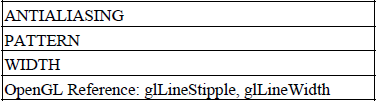
The LineAttributes class controls the style of lines used to draw the edges of surfaces. See table 9.2. The available styles are:
To see the effect of the LineAttributes class, the Appearance must be set to render in LINE (wire frame) mode:
Appearance app = new Appearance();
PolygonAttributes polyAttribs = new PolygonAttributes( PolygonAttributes.POLYGON_LINE, PolygonA
app.setPolygonAttributes(polyAttribs );
See section 9.7.1 for more detail on PolygonAttributes. Figures 9.3–9.6 show examples rendered using various LineAttribute styles.
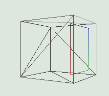
Figure 9.3 Rendering in LINE mode with a null LineAttributes
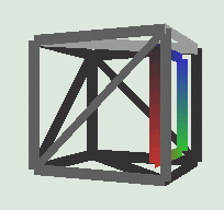
Figure 9.4 Rendering with a LineAttributes of width 10 without antialiasing
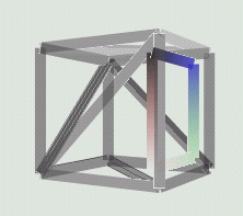
Figure 9.5 Rendering with a LineAttributes of width 10 with antialiasing
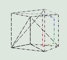
Figure 9.6 Rendering with a LineAttributes of width 2 with a Dash Dot pattern
The lines rendered in LINE mode are effected by color, lighting, and texture applied to surfaces.
java.lang.Object
|
+--javax.media.j3d.SceneGraphObject
|
+--javax.media.j3d.NodeComponent
|
+--javax.media.j3d.Material
Table 9.3 Capability bits for the Material class
The Material class specifies surface rendering characteristics (table 9.3) using the following parameters:
Ambient
Diffuse
Emissive
Specular
The effects of the various colors specified within the Material are described in detail in the context of lighting in chapter 10. Figure 9.7 shows a cube rendered with an applied Material, and per-vertex colors on four vertices of the cube.
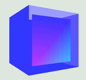
Figure 9.7 Appearance with an applied Material with Ambient, Diffuse, Emissive, and Specular colors. Lighting calculations determine the shade of each surface
java.lang.Object
|
+--javax.media.j3d.SceneGraphObject
|
+--javax.media.j3d.NodeComponent
|
+--javax.media.j3d.PointAttributes
Table 9.4 Capability bits for PointAttributes class
The PointAttributes class specifies rendering information for rendered points (table 9.4).
PointAttributes encapsulates two appearance properties:
If antialiasing is enabled, points are rendered as circular; if antialiasing is disabled, points are rendered as square (size pixels by size pixels) as shown in figures 9.8 and 9.9.
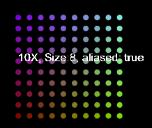
Figure 9.8 An array of colored points of size 8 pixels with antialiasing
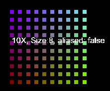
Figure 9.9 The same as in figure 9.8 but without antialiasing set in the PointAttributes
NOTE
The time taken to render a point (at least without hardware acceleration) is proportional to the size of the point in pixels.
Note that a single point, when antialiased, approximates a sphere, in that it is never possible to view the point “edge-on” as a disc. When points are rendered without antialiasing, the point approximates a cube with each front face always perpendicular to the viewer. Figures 9.10 and 9.11 illustrate.
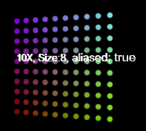
Figure 9.10 When rotated, antialiased points appear as spheres
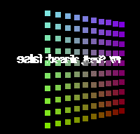
Figure 9.11 When rotated, nonantialiased points appear as squares aligned with the viewer
The figures are taken from the PointTest.java example. The example defines the points to be rendered, as well as Appearances, as follows:
//create a BranchGroup containing an nNumPoints x nNumPoints
//array of points
//the size of the points is set to nPointSize and antialiasing
//is set to bAliased
private BranchGroup createPoints( final int nPointSize, final int nNumPoints, boolean bAliased )
{
BranchGroup bg = new BranchGroup();
//create a Text3D label describing the points
String szText = new String();
szText += ( nNumPoints + "X, Size:" + nPointSize + ", aliased:
" + bAliased );
Font3D f3d = new Font3D( new Font( "SansSerif", Font.PLAIN, 1),
new FontExtrusion() );
Text3D label3D = new Text3D( f3d, szText, new Point3f(-5,0,0)
); Shape3D sh = new Shape3D( label3D );
bg.addChild( sh );
//create the PointArray used to hold the geometry for the points
PointArray pointArray = new PointArray( nNumPoints * nNumPoints, GeometryArray.COORDINATES | GeometryArray.COLOR_3 );
//populate the PointArray that we will be rendering
int nPoint = 0;
final double factor = 1.0 / nNumPoints;
for( int n = 0; n <nNumPoints; n++ )
{
for( int i = 0; i <nNumPoints; i++ )
{
Point3f point = new Point3f( n - nNumPoints/2,
i - nNumPoints/2, 0.0f );
pointArray.setCoordinate( nPoint, point );
pointArray.setColor( nPoint++,
new Color3f( 0.5f, (float) (n * factor),
(float) (i * factor) ) );
}
}
//create the Appearance for the points
Appearance pointApp = new Appearance();
//enlarge the points and set antialiasing
pointApp.setPointAttributes( new PointAttributes
( nPointSize, bAliased ) );
//create a Shape3D for the PointArray and assign the appearance
Shape3D pointShape = new Shape3D( pointArray, pointApp );
//add the Shape3D to the BranchGroup and return
bg.addChild( pointShape );
return bg;
}
java.lang.Object
|
+--javax.media.j3d.SceneGraphObject
|
+--javax.media.j3d.NodeComponent
|
+--javax.media.j3d.PolygonAttributes
Table 9.5 Capability bits for the PolygonAttributes class
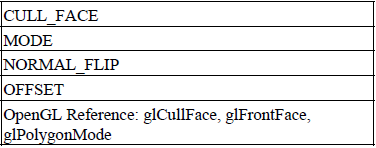
The PolygonAttributes class encapsulates properties for how polygons are rendered (table 9.5). Polygon rendering is controlled by the following properties:
For example, to allow write access to the CULL_FACE property, use the following:
PolygonAttributes polyAttribs = new PolygonAttributes();
polyAttribs.setCapability(PolygonAttributes.ALLOW_CULL_FACE_WRITE );
Table 9.6 Cull face parameters
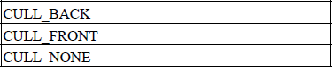
Cull face parameters (table 9.6) can be implemented as follows:
polyAttribs.setCullFace( PolygonAttributes.CULL_BACK );
Table 9.7 Mode parameters
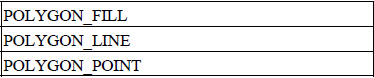
Polygon fill-mode parameters are shown in table 9.7. For example, to set line-only (wire frame) mode, use the following:
polyAttribs.setPolygonMode( PolygonAttributes.POLYGON_LINE );
Figures 9.12 through 9.15 illustrate how normal vector flipping can influence both the lighting calculations, (compare the shading of the horizontal faces in figure 9.12 with figure 9.13), and surface culling (figure 9.14, 9.15).
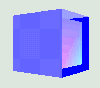
Figure 9.12 CULL_NONE, NORMAL_FLIP = false
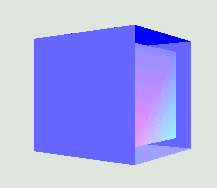
Figure 9.13 CULL_NONE, NORMAL_FLIP = true
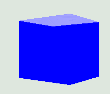
Figure 9.14 CULL_FRONT, NORMAL_FLIP = false
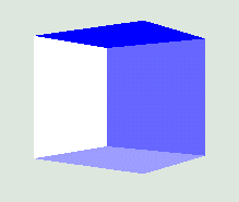
Figure 9.15 CULL_FRONT, NORMAL_FLIP = true
java.lang.Object
|
+--javax.media.j3d.SceneGraphObject
|
+--javax.media.j3d.NodeComponent
|
+--javax.media.j3d.RenderingAttributes
Table 9.8 Capability bits for the RenderingAttributes class
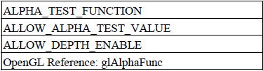
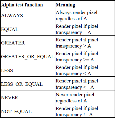
The RenderingAttributes class allows pixels within the final rendered scene to be included or excluded based on the pixel Alpha (transparency) value (table 9.8).
Assuming an Alpha test value of A, the test conditions listed in table 9.9 and shown in figure 9.16 are available.
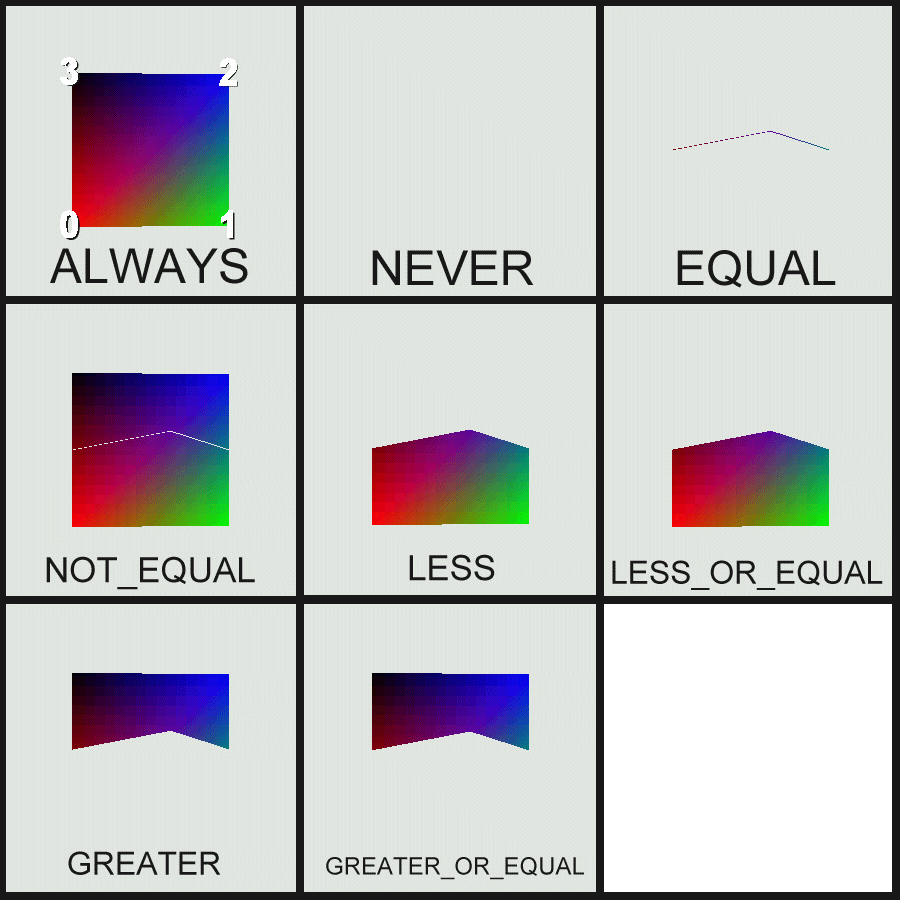
Figure 9.16 Using RenderingAttributes to control the portions of a QuadArray that are rendered. Vertex 0 has transparency 0.0, vertex 1 has transparency 0.2, vertex 2 has transparency 0.8, and vertex 3 has transparency 1.0. In all cases the Alpha test value was set to 0.5
Table 9.9 Alpha test modes
The interpolation of transparency values across primitives (quads or triangles) can sometimes be surprising. Figure 9.17 illustrates what happens to a QuadArray when it is rotated. In this case vertexes 0 and 1 have a transparency of 0.0, and vertexes 1 and 2 have a transparency of 1.0.
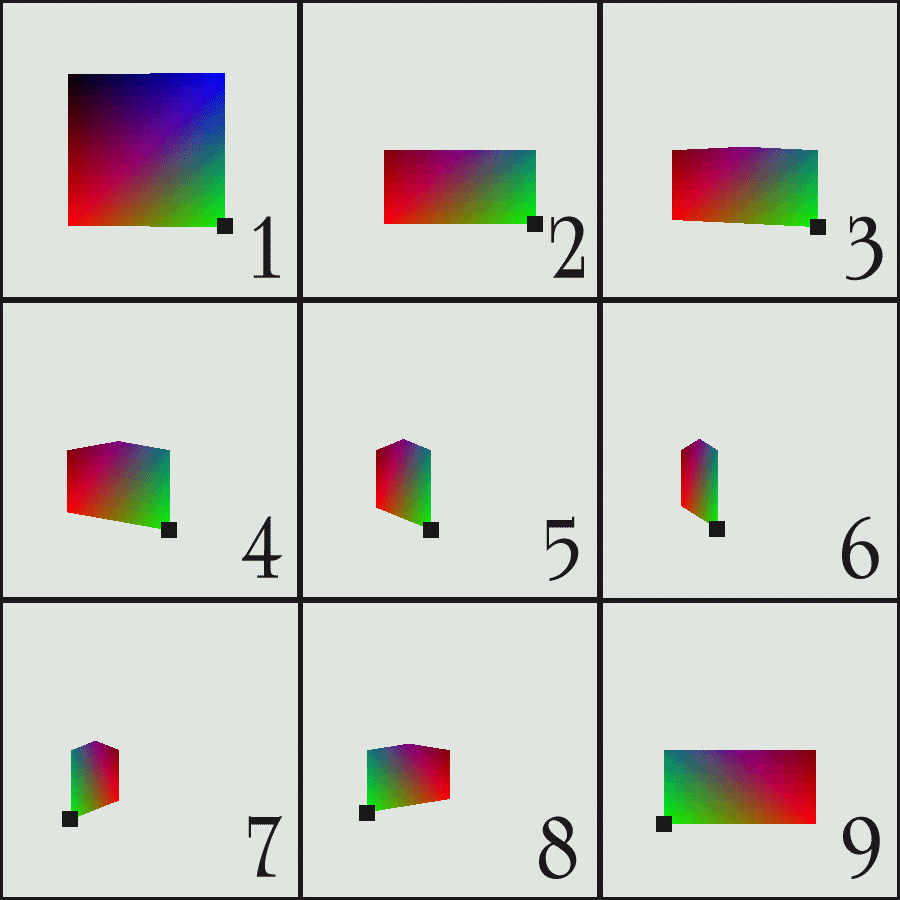
Figure 9.17 The lower two vertices have transparency 0.0, while the upper two vertices have transparency 1.0. The Alpha test value is 0.5 and Alpha test function is LESS. Note that, as the QuadArray rotates, the transparency interpolation changes as a function of the rotation and an apparent spike appears in the middle of the quad
java.lang.Object
|
+--javax.media.j3d.SceneGraphObject
|
+--javax.media.j3d.NodeComponent
|
+--javax.media.j3d.TexCoordGeneration
Table 9.10 Capability bits for the TexCoordGeneration class