Lights
10.7 Lighting, material attributes, and per-vertex colors
Lighting is an important topic in 3D graphics. The lights that you choose for your scene can have a profound impact, making it appear, for examples, highly atmospheric or almost photographically realistic or flat and artificial. There are two basic problems with setting up lighting for your scene. The first is to understand how lighting is calculated, as well as understanding the mechanics of setting up lighting parameters and doing the necessary programming. The second problem is aesthetic and involves making artistic decisions regarding how you want your scene to appear. Because lights can also be computationally expensive, you need to use them carefully and ensure you are striking the right balance between frame rate and responsiveness on the one hand and a richly shaded scene on the other.
Figures 10.2 through 10.15 show a scene viewed under different lighting conditions. The illustrations give an indication of the lighting effects that are possible using Java 3D and provide a starting point for designing your own scene lighting. You’ll want to run the example application to see the color illustrations for the full effect. You can also refer to the ebook edition of this book, available from the publisher’s web site at http://www.manning.com/selman , which contains color illustrations.
The LightTest example application allows you to interactively modify lighting parameters and view the results.
Careful use of lights can make the difference between a flat, unconvincing 3D scene and an atmospheric, immersive virtual reality. The shading that results from applying lighting to a 3D scene provides many of the important visual cues that convey the depth information for the scene.
There are four basic types of light defined in Java 3D and most 3D rendering APIs:
Lights positioned within the scene influence the colors that are applied to surfaces. Lights are not visible entities in themselves, but they affect the colors of the surfaces of objects within the scene. For example, there is no built-in support for displaying shafts of light that illuminate fog or dust before falling onto the surfaces of objects in the scene. Other lighting side effects, like lens-flare, are also not supported. Such visual effects, now commonly seen is 3D games such as Quake, are not implemented in either OpenGL or DirectX and hence not supported in Java 3D.
Once the lights are positioned within the scene, complex lighting equations govern the resulting color and shading of a surface. The result, a rendered shaded surface, relies on many factors, such as:
angle of surface relative to light sources
material properties: ambient, diffuse, emissive and specular colors, shininess (or gloss)
surface simulation: e.g., bumpy or wrinkled vertex colors
transparency
applied texture image
shading model (Lambert, Gouraud, Phong)
position
color
direction
attenuation: how the intensity of the light decreases with distance
concentration
spread angle
extent (Bounds)
10.1.1 Lighting equations
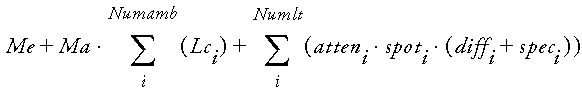
A mathematical equation (from the Java 3D Specification) determines the color of a pixel given the positions and colors of lights, Material properties of the pixel’s surface, normal vector for the surface, and position of the viewer. The lighting equation used in Java 3D is a simplification of the OpenGL lighting equation.
Note that
Multiplication
Dot product
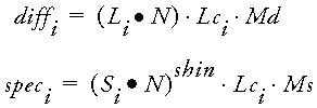
Note that if ![]() , then diffi and speci are set to 0.
, then diffi and speci are set to 0.
![]()
Note that for directional lights, atteni is set to 1.
![]()
Note that if the vertex is outside the spotlight cone, as defined by the cutoff angle, spoti is set to 0. For directional and point lights, spoti is set to 1.
The lighting equation is a subset of OpenGL in that the Java 3D ambient and directional lights are not attenuated and only ambient lights contribute to ambient lighting.
The parameters used in the lighting equation are:
E = Eye vector
Ma = Material ambient color
Md = Material diffuse color
Me = Material emissive color
Ms = Material specular color
N = Vertex normal
shin = Material shininess
The per-light values are:
di = Distance from vertex to light
Di = Spotlight direction
expi = Spotlight exponent
Kci = Constant attenuation
Kli = Linear attenuation
Kqi = Quadratic attenuation
Li = Direction from vertex to light
Lci = Light color
Si = Specular half-vector = || (Li + E) ||
The basic principle of the lighting equations is fairly simple—if a surface is close to 90 degrees to a light ray, then the surface will be brightly lit. That is, large quantities of the light reaching the surface are absorbed by the surface and hence visible. The color used to brightly light the surface will be related to the color of the light as well as the color of the surface.
10.1.2 Normal vectors and lighting
The lighting equation requires that you define a normal vector for each vertex that you want to be lit. The lighting equation will interpolate the surface color between the vertices in the surface based on the vertex position and normal vector. There are a number of algorithms used to interpolate surface color between vertices, described in the sections that follow.
Lambert shading
The simplest lighting model merely colors a surface in proportion to its angle relative to the viewer. This is commonly referred to as Lambert or cosine shading. To establish the intensity of the surface, the model uses the cosine of the angle between the ray of light hitting the surface and the surface normal. As the light source comes to be closer to perpendicular to the surface, so the angle between the light ray and the surface normal decreases and the surface lightens. When the light is at right angles to the surface, the angle is zero and the intensity is at a maximum.
Lambert shading is extremely fast to calculate and produces a marked improvement in depth perception for the scene. It produces faceted models, as if each surface had been cut from glass, and tends to emphasize the edges between surfaces.
Often it is preferable that the individual surfaces that comprise the model be calculated to approximate a smooth edge, but, by emphasizing the surface decomposition as much as the model itself, Lambert shading can make the model appear artificial. In 1971, Henri Gouraud published an improved shading model that generates smooth shading across surfaces—preserving the depth cues inherent in Lambert shading while not emphasizing the edges between surfaces.
Gouraud shading
In Gouraud shading, instead of assigning a single intensity to a surface, the average intensities at each vertex are calculated. Once the average intensity of each vertex is calculated the intensities are then interpolated along each scan line between these averages to give a smooth appearance. A given vertex might be shared between several surfaces, and hence its normal vector can influence the intensity of each of the surfaces to which it contributes.
Phong shading
Two years after Gouraud, Bui Tuong Phong developed an algorithm to incorporate specular highlights into the intensity interpolation algorithm developed by Gouraud. So-called Phong shading computes an approximate normal vector for each point along the scan lines. These intermediate normal vectors can then be used to calculate an intensity based partly on the interpolated Gouraud shading component and partly from a point’s normal vector.
Consider a triangular surface where the averaged normal vector for two of the vertices was a little less than 90 degrees while the averaged normal vector for the third vertex was a little more than 90 degrees. If the surface were Gouraud shaded, the interpolated intensities would be fairly uniform across the surface (as the cosine of the angle for each normal vector would be approximately equal). However, the planar surface is probably intended to model a smooth surface fitted between the vertices of the surface. If this is the case, then at some point across the surface, the normal vector must reach 90 degrees. This point, within the surface, should therefore be assigned a higher intensity than any of the vertices at the edges of the surface. Phong shading, by interpolating the normal vectors across the surface, as well as Gouraud intensity, can introduce local highlights that would otherwise be merely averaged into the intensity of the surface as a whole. Phong introduced a new coefficient for each surface, called shininess, that controls how radically the surface responds to light and influences the size of a surface’s specular highlight.
An interesting compromise must be made between Lambert and Gouraud shading, as the averaging behavior of Gouraud shading must be balanced with the facet display behavior of Lambert shading. Using Gouraud shading, it is easy to display a coarsely triangulated sphere that is beautifully and smoothly shaded and has Phong specular highlights applied, but whose edges are straight—and belie the faceted nature of the model.
Notice that these three components are visible in the Java 3D lighting equations given in section 10.1.1. As should be clear from these equations, lights are expensive computationally and you should design your scene’s lighting requirements in the context of general application performance and usability. With artful design, however, apparently complex lighting can be created with a fairly modest number of lights. The surface smoothing characteristics of the lighting equations can also be gainfully employed to give coarsely meshed models a smoother appearance. If the models in the scene contain fewer vertices, the scene may render quicker, even with the added overhead of a more complex shading model.
NO NORMALS...
NO SHADING
It is critical to note that, however you decide to light your models, all of the shading algorithms rely on the normal vectors that have been assigned to the vertices of the models. As an application developer it is your responsibility to tell the renderer about the normal vector for each of your vertices, just as it is your responsibility to tell the render about the position of each vertex! The Java 3D NormalGenerator class can be used to generate the normal vectors for a model. Failure to assign normal vectors will typically result in a uniformly shaded model that offers no depth cues through shading surfaces.
10.1.3 Lighting and material properties
Examining the lighting equation one can see how the various material properties for the surface interplay.
The emissive (Me) and ambient (Ma) color of the surface are combined irrespective of vertex-normal vectors, and the position or color of lights in the scene.
The diffuse color (Md) of the surface is combined with the color of each light (Lci) and applied relative to the angle between each light and each vertex normal. If the light and the normal vector are perpendicular there is no diffuse color component applied.
The material specular color (Ms) is combined with the light color (Lci) in proportion to the calculated specular component.
In other words,
10.1.4 What about shadows?
Note that the discussion has been devoid of any mention of shadows cast by objects onto other objects in the scene. This is because there is no built-in support for automatic shadow calculation in Java 3D or the lower level rendering APIs such as OpenGL or Direct3D.
Although this often comes as a surprise and a disappointment to many people new to rendering APIs, if you consider how you might go about calculating shadows for arbitrary 3D scenes, it quickly becomes apparent that a general purpose algorithm is unsuitable for interactive 3D graphics. The sheer amount of calculations that need to be performed means that application-specific cheats have to be developed that are able to mimic some of the effects of shadow casting. Lightweight shadow calculation algorithms are available in the OpenGL literature.
Realistic effects such as reflection, refraction, and shadows are best left to noninteractive applications that can make use of ray-tracing techniques. These techniques follow individual light rays as they bounce around the scene, having their color modified along the way, until they finally intersect with a pixel for display.
java.lang.Object
|
+--javax.media.j3d.SceneGraphObject
|
+--javax.media.j3d.Node
|
+--javax.media.j3d.Leaf
|
+--javax.media.j3d.Light
Light is an abstract base class for the four types of Light Leaf Node available in Java 3D:
AmbientLight, DirectionalLight, PointLight, and SpotLight.
This section is illustrated using the LightTest.java example program. LightTest is one of the longer examples in the book. It allows the four types of light to be positioned within the scene, and for the light properties to be modified at runtime. You can thus view the results interactively. The program will certainly not win any awards for UI design, but all the parameters for all the Java 3D Light classes can be modified at runtime. In addition, geometry is also created to represent the lights themselves: a Cone, whose base is set to the color of the light, denotes the SpotLight, while a large Cone through the center of the scene denotes the direction and color of the DirectionalLight. A small Sphere is created for the PointLight.
The LightTest example, shown in figure 10.1, creates the four lights and a simple 3D scene consisting of several Spheres with a checkered floor composed from a QuadArray.
10.2.1 Light properties
Light defines all the properties necessary for a simple ambient light. An ambient light shines equally everywhere within its zone of influence and does not possess position or direction. Such a light is of course a practical impossibility, much like frictionless surfaces or the perfect collisions beloved of physicists.
Color
A Light has a color. If no color is specified a 100 percent white light is created.
Influencing bounds
A Bounds object is associated with each Light. The Bounds object defines the zone of influence for the Light. Note that for Lights that possess positional information (SpotLight and PointLight) the Bounds is completely independent of the position of the Light. It is the application developer’s responsibility to ensure that the Bounds of the Light and the position of the Light correspond in some sensible application-specific manner.
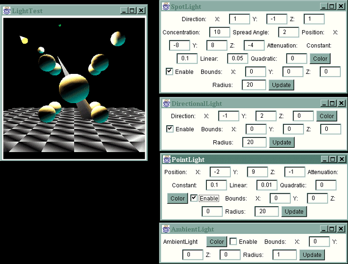
Figure 10.1 The LightTest example program allows you to interactively modify lighting parameters for the four types of light object in Java 3D: SpotLight, DirectionaLight, PointLight, and AmbientLight. The Cone at the top left of the figure depicts the SpotLight, the small Sphere at the top middle of the figure depicts a PointLight, while the large cone at the center of the scene depicts the DirectionalLight’s direction vector
Scope
Defining scopes for lights is an additional mechanism to restrict the zone of influence of a Light. An object in the scene will be lit only if it falls within the Bounds of a light and the Group containing the object is included in the scope of the Light. In other words, the scope information for a light takes precedence over the Bounds information for the Light. By default, Lights do not contain any scopes, and the Bounds set for the Light will solely define its zone of influence.
State
The state for lights is very simple—ON or OFF.
AmbientLight simply inherits the properties defined in the base-class Light object. AmbientLight instances illuminate a scene evenly, without direction or attenuation characteristics. AmbientLights are useful in illuminating the dark areas left by the other types of Light. Because an AmbientLight does not possess a direction, it lights a scene with an even, flat light. Because this kind of light does very little to increase 3D perception, it is typically used in combination with one of the other lights.
AmbientLights are very simply handled by the rendering engine (illumination is independent of surface orientation). Thus, they are, computationally, the cheapest of the types of Light.
NOTE AmbientLight is a cheap approximation of many diffuse light sources, such as in a well-lit office building with many windows and overhead lighting.
A DirectionalLight is a light that is assumed to shine from an infinite distance—for example, to model sunlight. It allows a Vector3f object to be assigned to the light to specify the direction. DirectionalLight can be very useful in providing simple 3D cues to the user of an application.
Illumination of surfaces depends upon the orientation of the surface relative to the DirectionalLight vector, so a DirectionalLight is computationally more expensive that an AmbientLight.
NOTE DirectionalLight is an approximation of a shaft of light entering a scene, such as a shaft of sunlight entering a room through one glass wall.
A PointLight is a light that shines from a given point within the 3D scene. Although the light source itself is invisible, the effects of the light vary with distance and orientation of the surface upon which it falls. A PointLight is computationally more expensive than a DirectionalLight because each object in the scene must have both orientation and distance relative to the light evaluated.
A PointLight contains attenuation properties that define how the brightness falls off with distance. The attenuation contains three components:
NOTE
A PointLight is an approximation of a point light source, such as a light bulb hanging from the ceiling of a large room. As one moves further toward the corners of the room the illumination from the light lessens (attenuates).
A SpotLight is a light that shines from a given location and in a given direction.
The SpotLight is the most computationally expensive of the light types, as distance from the light source, surface orientation, and distance from the center of the conical beam must all be evaluated for all objects within a SpotLight’s zone of influence.
A SpotLight contains two properties:
NOTE
A SpotLight is an approximation of a typical directional light source, such as a flashlight, car headlight, or desk lamp. The width of the conical beam for the Spotlight can be varied, along with the position and attenuation of the light.
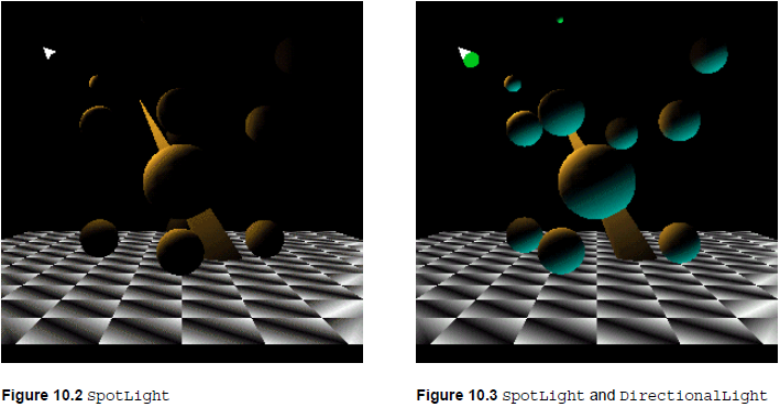
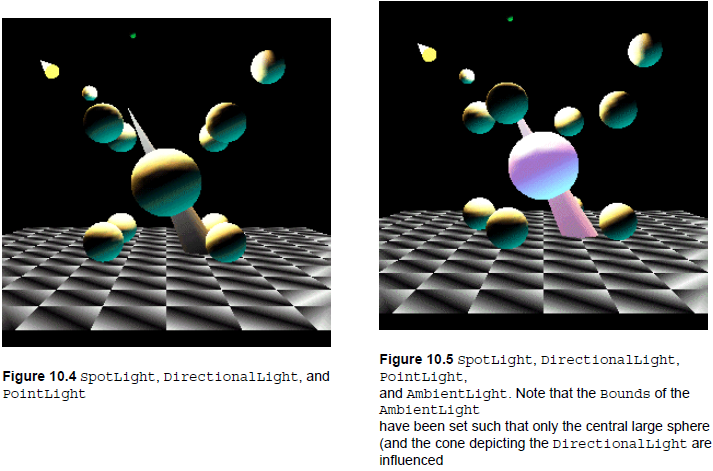
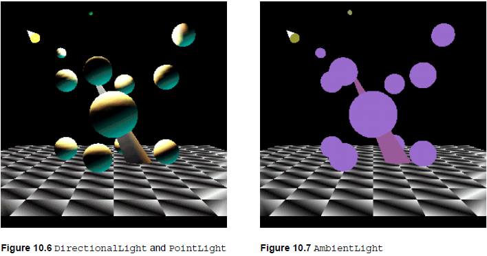
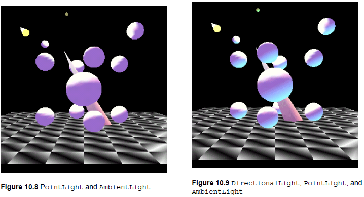
Figures 10.2 through 10.9 illustrate the effects of applying the different types of light to a simple scene.
The relevant parameters for the lights are shown in tables 10.1 through 10.3.
Table 10.1 Spotlight
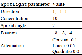
Table 10.2 DirectionalLight
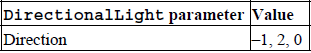
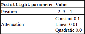
Table 10.3 PointLight
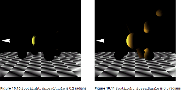
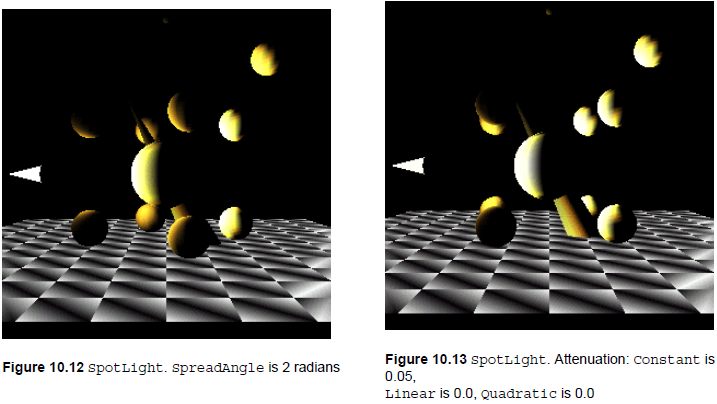
Figures 10.10 through 10.12 illustrate the effect of varying the SpreadAngle for a single SpotLight.
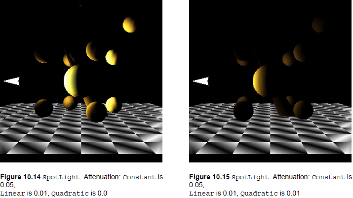
Figures 10.13 through 10.15 illustrate varying the attenuation parameters of a SpotLight. As the linear and quadratic components of the attenuation are increased, the boundary between lit and unlit surfaces becomes increasingly blurred because the light attenuates more rapidly with distance.
10.7 Lighting, material attributes, and per-vertex colors
The Lights in a scene, an object’s material attributes (specifying ambient, emissive, diffuse, and specular color for an object), and the colors that have been assigned to the vertices of an object all interact to produce the final rendered surface.
If lighting or color information is not displayed correctly, note the following points:
Java 3D 1.2 includes the setIgnoreVertexColors method in the RenderingAttributes class that allows this default behavior to be overridden.
I hope this chapter has inspired you to create some great lighting effects for your 3D world. As you can see, the possible ways to combine the lights and their different parameters are almost endless. I encourage you to run the LightTest example to learn how the different lighting parameters can be combined to create the effect you want. After you have a sense for the number of lights you will require, you should test your application with representative geometry loaded to ensure that your choice of lights performs well on your target hardware platform.