Direct reading RF power meters either contain a non-reactive load or use an external load and may be calibrated in watts or dBm. RF calorimeters convert the RF energy into heat and measure the temperature of the heated element. At low powers, ‘dry’ calorimeters are used but their long thermal time constant inhibits their use at high power levels. To measure high powers ‘flow’ calorimeters, where a fluid flows around a closed system and the output temperature of the fluid is measured, are used. Power can be determined from:
P =F(Tout− Tin)c(T )where
P = power
F = mass flow rate of the fluid
Tin = temperature of the fluid entering the load
Tout = temperature of the fluid after being heated by the load Thruline type instruments require an external load which may be either an antenna system or a load resistor. This type of meter reads forward and reflected power and, in some instruments, VSWR directly.
The range of instruments designed for use on specific systems, e.g. cellular and digitally modulated, is so wide that manufacturers’ catalogues must be consulted for each application. In addition to the accuracy of the carrier frequency and output level, RF leakage, spectral purity and modulation noise levels are important. The output level may be calibrated in µV, dBV or dBm, and may refer to either an unterminated instrument (p.d.) or terminated in a load equal to the output impedance of the generator (e.m.f.). If the instrument is calibrated in p.d., the output voltage must be halved when the instrument is terminated in an equal impedance.
The 50 ohm output impedance of many signal generators matches the input impedance of most VHF and UHF receivers directly. To simulate the impedance of antennas at HF and below a dummy antenna is usually inserted between the generator and the receiver under test. Figure 20.2 shows the circuit of a standard dummy antenna.
200 pfd 20 µHInstruments are necessary to measure not only the precise frequencies of transmitters and receiver local oscillators but also those of low frequency signalling tones. Consequently they have a wide operating range.
The output of a transmitter must never be connected directly into a counter. The signal should either be obtained off-air or through a ‘sniffer’, appropriate for the frequency range, which siphons off a fragment of the transmitter output. It is also essential to ensure that the frequency displayed is the fundamental and not a harmonic or some other spurious frequency.
The remarks in the above section relating to the connection of a transmitter and the selection of the fundamental frequency apply equally to modulation meters.
Today’s tight regulation of spectrum usage makes a spectrum analyser an essential tool for the precise alignment of radio equipment and for the measurement of modulation products and the noise content of signals.
A spectrum analyser is essentially a superheterodyne receiver with an adjustable IF bandwidth which sweeps across a portion of the frequency spectrum in synchronism with the horizontal trace of a cathode ray tube display. A signal at any frequency within the swept band will, while it remains within the IF passband, appear as a vertical displacement of the display trace. The design of the filter is crucial but must be a compromise. An analyser using multiple filters permits fast measurement but low resolution; a single filter offers high resolution but slower response time. Also, the shape factor of a wide filter inhibits the display of low level signals close to the centre frequency of the filter and a narrow filter, while permitting the display of these signals, may fail to display transients. The bandwidth determines the sweep speed, narrower bandwidths requiring slower speeds.
The possibility exists of spurious signals, e.g. intermodulation, being produced within the analyser with large input signals. A method of reducing the possibility is to insert a circulator and a notch filter
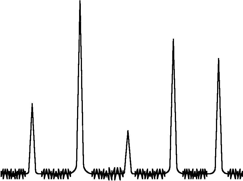 Figure 20.3 Amplitude-vs-frequency spectrum analyser display
between the unit under test and the analyser input to reduce the fundamental frequency amplitude. The circulator must be installed between the filter and the unit under test to absorb the reverse power produced by the impedance variations of the filter.
Many instruments are programmable and suitable for incorporation in automatic testing (ATE) systems, and instruments with similar features to those described are also offered in a combination test set form.
A network analysers examines incident, reflected and transmitted signals through a circuit or device, and displays the magnitude and phase of these signals. A spectrum analyser, on the other hand, measures only one channel, and displays magnitude and frequency.
Figure 20.4 shows an optical analogy to the network analyser. A ‘device’ of different optical density than ambient is in the path of an incident ray of light (R). When the light hits the surface, part of it is reflected (A) and part is transmitted through the ‘devices’ (even though refracted a bit).
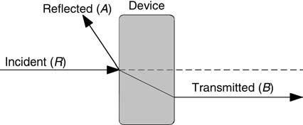 Figure 20.4 Optical analogy to network analyser
A network analyser consists of a three-channel RF receiver and a display. The incident signal is considered the reference signal,sois designated the R-channel. The other two channels receive the reflected signal on the A-channel, and the transmitted signal on the B-channel.
The uses of scalar and vector network analysers differ from the uses of spectrum analysers. The spectrum analyser measures external signals of unknown frequency and modulation type. Even when a tracking generator is added, to allow the spectrum analyser to perform stimulus-response tests, the spectrum analyser cannot do the job of the network analyser. The network analyser, by contrast, contains a known signal source, and is capable of sweeping a range of frequencies and power output levels. It can also perform ratio measurements.