(L− 1)TFN(COAX) = 1+290
where
FN(COAX) is the noise factor of the coax
L is the loss expressed as a linear quantity
T is the physical temperature of the cable in Kelvins
The linear noise factor due to loss can be converted to the noise figure by 10 log(FN(COAX)), which can be added to the system noise decibel for decibel.
The attenuation loss figure published in manufacturers’ tables is called the matched line loss (LM) because it refers to the situation where the load and characteristic impedance of the line are equal. But we also have to consider the Total Line Loss (TLL), which is:
TLL=
10 log
B2 − C2 B(1− C2)
where
B = antilog LM
C = (SWRLOAD − 1)/(SWRLOAD + 1)
Coaxial cable consists of two cylindrical conductors sharing the same axis (hence ‘co-axial’) and separated by a dielectric. For low frequencies (in flexible cables) the dielectric may be polyethylene or polyethylene foam, but at higher frequencies TeflonÚ and other materials are used. Also used in some applications, notably high powered broadcasting transmitters, are dry air and dry nitrogen.
Several forms of coaxial line are available. Flexible coaxial cable discussed earlier in this chapter is perhaps the most common form. The outer conductor in such cable is made of either braided wire or foil. Again, television broadcast receiver antennas provide an example of such cable from common experience. Another form of flexible or semi-flexible coaxial line is helical line (Figure 3.7) in which the outer conductor is spiral wound. This type of coaxial cable is usually 2.5 or more centimetres in diameter.
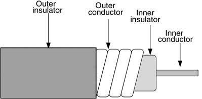 Figure 3.7 The helical line
Hardline is coaxial cable that uses a thin-walled pipe as the outer conductor. Some hardline coax used at microwave frequencies has a rigid outer conductor and a solid dielectric. Gas-filled line is a special case of hardline that is hollow (Figure 3.8), the centre conductor
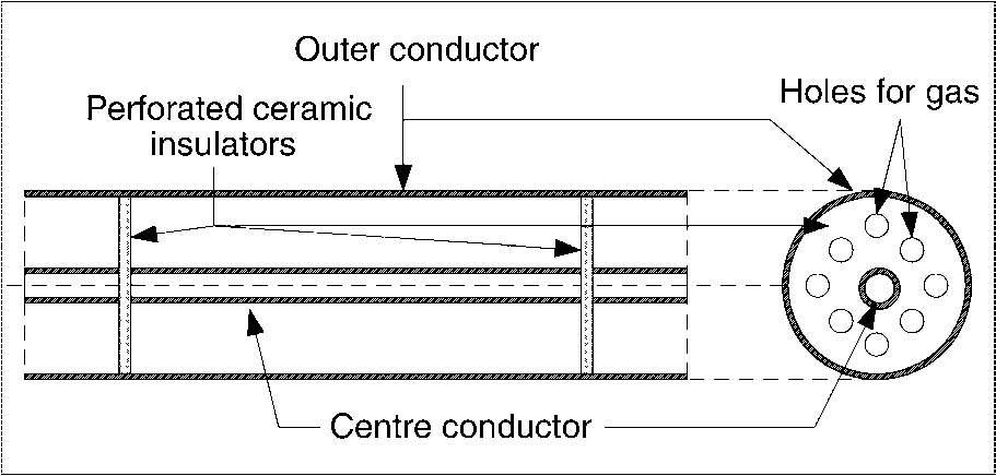 Figure 3.8 Gas-filled line
being supported by a series of thin ceramic or Teflon insulators. The dielectric is either anhydrous (i.e. dry) nitrogen or some other inert gas. Some flexible microwave coaxial cable uses a solid ‘air-articulated’ dielectric (Figure 3.9), in which the inner insulator is not continuous around the centre conductor, but rather is ridged. Reduced dielectric losses increase the usefulness of the cable at higher frequencies. Double shielded coaxial cable (Figure 3.10) provides an extra measure of protection against radiation from the line, and EMI from outside sources from getting into the system.
 Figure 3.9 Solid ‘air-articulated’ dielectric
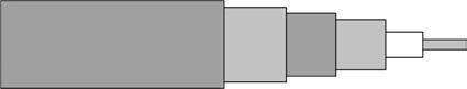 Figure 3.10 Double shielded coaxial cable
Transmission lines are capable of generating noise and spurious voltages that are seen by the system as valid signals. Several such sources exist. One source is coupling between noise currents flowing in the outer and inner conductors. Such currents are induced by nearby electromagnetic interference and other sources (e.g. connection to a noisy ground plane). Although coaxial design reduces noise pick-up compared with parallel line, the potential for EMI exists. Selection of high-grade line, with a high degree of shielding, reduces the problem.
Another source of noise is thermal noise in the resistances and conductances of the line. This type of noise is proportional to resistance and temperature.
There is also noise created by mechanical movement of the cable. One species results from movement of the dielectric against the two conductors. This form of noise is caused by electrostatic discharges in much the same manner as the spark created by rubbing a piece of plastic against woollen cloth.
A second species of mechanically generated noise is piezoelectricity in the dielectric. Although more common in cheap cables, one should be aware of it. Mechanical deformation of the dielectric causes electrical potentials to be generated.
Both species of mechanically generated noise can be reduced or eliminated by proper mounting of the cable. Although rarely a problem at lower frequencies, such noise can be significant at microwave frequencies when signals are low.
24ε pFC = log(D/d)Metre
where
C is the capacitance
D is the outside conductor diameter
d is the inside conductor diameter
ε is the dielectric constant of the insulator.
A long run of coaxial cable can build up a large capacitance. For example, a common type of coax is rated at 65 pF/metre. A 150 metre roll thus has a capacitance of (65 pF/m) (150 m), or 9750 pF. When charged with a high voltage, as is done in performing breakdown voltage tests at the factory, the cable acts like a charged high voltage capacitor. Although rarely if ever lethal to humans, the stored voltage in new cable can deliver a nasty electrical shock and can irreparably damage electronic components.
The normal mode in which a coaxial cable propagates a signal is as a transverse electromagnetic (TEM) wave, but others are possible – and usually undesirable. There is a maximum frequency above which TEM propagation becomes a problem, and higher modes dominate. Coaxial cable should not be used above a frequency of:
FCUT−OFF =3.76(D
1 √ε +d)
where
F is the TEM mode cut-off frequency D is the diameter of the outer conductor in mm d is the diameter of the inner conductor in mm
ε is the dielectric constant
When maximum operating frequencies for cable are listed it is the TEM mode that is cited. Beware of attenuation, however, when making selections for microwave frequencies. A particular cable may have a sufficiently high TEM mode frequency, but still exhibit a high attenuation per unit length at X or Ku-bands.