Stated as a percentage of the nominal design frequency, the bandwidth of an antenna is the band of frequencies over which it is considered to perform acceptably. The limits of the bandwidth are characterized by unacceptable variations in the impedance which changes from resistive at resonance to reactive, the radiation pattern, and an increasing VSWR.
In directional antennas the beamwidth, sometimes called half-power beamwidth (HPBW), is normally specified as the total width, in degrees, of the main radiation lobe at the angle where the radiated power has fallen by 3 dB below that on the centre line of the lobe (Figure 4.1A).
Half-power (3 dB) points52 completely passive; they cannot increase the power applied to them. Nevertheless, it is convenient to express the enhanced radiation in some directions as a power gain.
Antenna gain may be quoted with reference to either an isotropic radiator or the simplest of practical antennas, the dipole. There is a difference of 2.15 dB between the two figures. A gain quoted in dBi is with reference to an isotropic radiator and a gain quoted in dBd is with reference to a dipole. When gain is quoted in dBi, 2.15 dB must be subtracted to relate the gain to that of a dipole.
The current flowing in an antenna varies along its length (see Figure 1.4). If the current were uniform along the length of an antenna it would produce a field appropriate to its physical length, and the effective height or length of the antenna would be its physical length. In practice, because the current is not uniform, the effective length is less than the physical length and is given by:
lphys× Imeanleff = Iwhere
leff = effective length
lphys = physical length
I = current at feed point
With an antenna which is short in comparison with a wavelength
the current can be considered to vary linearly over its length and
Imean =I/2. Because the apparent length of a vertical radiator is twice
that of its physical dimension due to the mirror image formed below
the ground, the effective length of an electrically short vertical antenna
may be approximated to be its physical length.
This is the power effectively radiated along the centre line of the main lobe. It is the power supplied to the antenna multiplied by the antenna gain with reference to a dipole.
The power radiated by an antenna can conveniently be expressed in terms of the value of a resistor which would dissipate the same power that the antenna radiates. This value is referred to as the radiation resistance and is defined as the ratio of the power radiated to the square of the current at the feed point. The efficiency is the ratio of the power radiated to that lost in the antenna. It is given by:
eff=
Rr+RLRr × 100%
where Rr is the radiation resistance and RL represents the total loss resistance of the antenna. The sum of the two resistances is the total resistance of the antenna and, for a resonant antenna, is also the impedance.
The ratio, in dB, of the strength of the radiation (or received signal) in the forward (desired) direction to that in the reverse (unwanted) direction. The front-to-back ratio of the antenna shown in Figure 4.1A is 13 dB.
The impedance of an antenna is that presented to the feeder cable connecting it to the transmitter or receiver. It is the result of the vectorial addition of the inductive, capacitive and resistive elements of the antenna. Each resonant antenna possesses an impedance characteristic of the type, and when an antenna operates at its resonant frequency the reactive elements cancel out and the impedance becomes resistive. The radiation resistance plus the losses in the antenna, i.e. the series resistance of the conductors, the shunt resistance of the base material and losses in nearby objects, form the resistive portion of the impedance.
The radiated field from an antenna is considered to be polarized in the plane of the length of the conductors which is the plane of the electric field, the E plane. Confusion arises when reference is made to vertical or horizontal polarization and it is preferable when referring to polar diagrams to use the E and H plane references.
Circular polarization, produced by crossed dipoles or helical wound antennas, is occasionally used for point-to-point work at VHF and above to reduce multi-path propagation losses.
Cross polarization discrimination defines how effectively an antenna discriminates between a signal with the correct polarization, i.e. mounted with the elements in the same plane, and one operating at the same frequency with the opposite polarization. 20 dB is typical.
A plot of the directivity of an antenna showing a comparison of the power radiated over 360æ. Two polar diagrams are required to show the radiation in the E and H planes. The polar diagrams may be calibrated in either linear (voltage) or logarithmic (decibel) forms.
Most VHF and UHF antennas contain an impedance matching device made up of lengths of co-axial cable. Thus the VSWR (see Chapter 3) of these types of antenna varies with the operating frequency, more so than the bandwidth of the antenna alone would produce. At the centre design frequency, the VSWR should, theoretically, be 1:1 but in practice a VSWR less than 1.5:1 is considered acceptable.
Receiving antennas also possess a property called aperture, or capture area. This concept relates the amount of power that is delivered to a matched receiver to the power density (watts per square metre). The aperture is often larger than the physical area of the antenna, as in the case of the half-wavelength dipole (where the wire fronts a very small physical area), or less as in the case of a parabolic reflector used in microwave reception. Figure 4.1B shows the capture area of a halfwavelength (0.5λ) dipole. It consists of an ellipse with major axes of 0.51λ and 0.34λ. The relationship between gain and aperture is:
Ae
=
Gλ2 4πn
Ae is the effective aperture
G is the gain
λ is the wavelength of the signal
n is the aperture effectiveness (n = 1 for a perfect no-loss
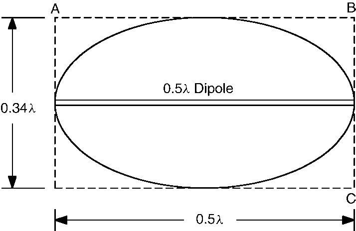 Figure 4.1B Captureareaofhalf-wavelength(0.5λ)dipole