The half-wavelength ( λ/2) dipole as described in Section 1.4 is the antenna on which many others are based. Figure 4.2 shows the relative radiation in the E and H planes of a dipole in free space.
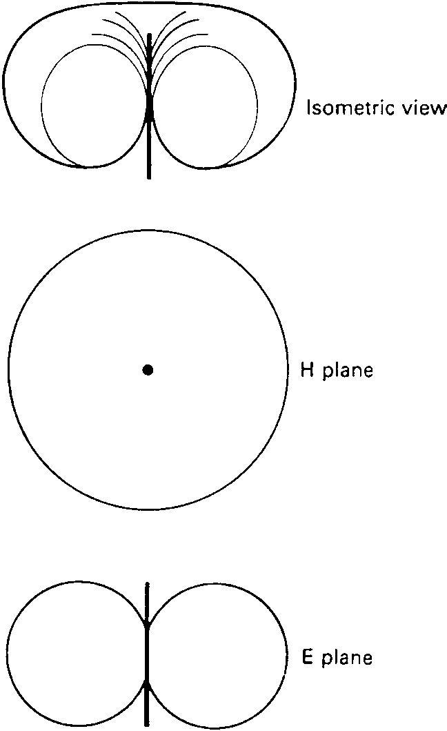 Figure 4.2 Radiation patterns of a half-wave dipole
The impedance of a half-wavelength dipole is 72 ;thatofa full wavelength or folded dipole is 300 .
The quarter-wavelength ( λ/4) vertical radiator is a commonly used antenna for MF broadcasting and for VHF and UHF mobile radio applications. It is derived from the λ/2 dipole and it is assumed that a mirror image of the radiator is formed below the ground to complete the λ/2 structure of the dipole as in Figure 4.3. The radiation pattern of a λ/4 vertical radiator mounted close to a perfect earth shows a strong similarity to that of a dipole. The effect of reducing the size and conductivity of the ground plane raises the angle of radiation.
Radiation withRadiation with perfect ground plane
Figure 4.3 Quarter-wavelength vertical radiatorThe impedance of a perfect λ/4 vertical radiator is 36 but reducing the effectiveness of the ground plane raises the impedance.
Because of the physical lengths involved, LF and MF antennas are usually non-resonant and their impedances do not conform to the resistive 70 or 36 of the basic resonant types. The impedance of a nonresonant antenna is usually higher and reactive so an antenna tuning or matching unit is used to couple the antenna efficiently to the transmission line and also act as filter to reduce out-of-band radiations. The matching unit comprises a tuned circuit with either a tap on the coil at the correct impedance point or a separate coupling coil to feed the antenna.
Obtaining an adequate length is always the problem with low frequency antennas and various methods have been used based mainly on the λ/4 radiator. The horizontal section of the inverted L (Figure 4.4) extends the effective length but, as the ground wave is much used at
Effectivethe lower frequencies, these antennas are intended for vertical polarization and it is therefore only the down-lead which radiates, or receives, effectively. An alternative method of increasing the effective height of a vertical radiator is to provide a capacitance top where the system of horizontal conductors provides a high capacitance to ground. This prevents the current falling to zero at the top of the antenna, maintaining a higher mean current and so increasing the antenna’s effective length.
Dipoles used at HF are mounted horizontally because of their length and have directivity in the horizontal (E) plane. Propagation is mainly by the sky wave and the omni-directional properties in the vertical (H) plane, modified by ground reflections, produce wide angle upwards radiation.
A broadside array consists of several radiators spaced uniformly along a line, each carrying currents of the same phase. When each radiator has an omni-directional pattern, and the spacing between radiators is less than 3λ/4, maximum radiation occurs at right angles to the line of the array. The power gain is proportional to the length of the array, provided that the length is greater than two wavelengths; this means, effectively, the number of radiators. Figure 4.5 shows a typical H plane polar diagram for an array with vertically mounted radiators and a spacing of λ/2.
Physically an end-fire array is identical to a broadside except for the feeding arrangements and the spacing of the elements. In an end-fire array the radiators are fed with a phase difference between adjacent radiators equal in radians to the spacing between them in wavelengths.
Dipoles Fed in phaseA spacing of λ/4 requires a phase shift of 90æ between adjacent radiators. Figure 4.6 shows a typical radiation pattern. An end-fire array concentrates the power in both the E and H planes and the maximum radiation is in the direction of the end of the array with the lagging phase.
FeedA rhombic is a wide band, directional antenna comprised of four nonresonant wire antennas, each several wavelengths long, arranged as shown in Figure 4.7(a) which also shows the radiation pattern for each leg of the rhombus. The lobe angle θ can be varied by adjusting the length, in wavelengths, of each radiator. The antenna has greater directivity than a single wire and can be terminated by an appropriate value resistor to ensure non-resonance and a wide bandwidth. However, because it must be terminated in a resistance equal to the characteristic impedance of the conductors, it cannot be more than 50% efficient. It also exhibits considerable side lobes of radiated power. Rhombics are used for sky wave working at HF and more than one frequency is allocated to allow for varying propagation conditions. The conductors of a rhombic are normally horizontal and the horizontal directivity is determined by the tilt angle, β in Figure 4.7(a). If the lobe angle θ is equal to (90−β)æ the radiation in the A lobes cancels, while that from the B lobes, which point in the same direction, is added. The resultant pattern in the horizontal plane is shown in Figure 4.7(b).The vertical directivity is controlled by the height of the conductors above the ground.
8 l q b bA qA Terminating resistor Z0
A
An alternative, usable from HF through UHF, to the rhombic for wide band operation is the log-periodic antenna. It is comprised of several dipoles of progressive lengths and spacings as in Figure 4.8,and is resonant over a wide frequency range and may be mounted with either polarization. The dipoles are fed via the support booms and this construction ensures that the resultant phasing of the dipoles is additive in the forward direction producing an end-fire effect. However, because at any one frequency only a few of the dipoles are close to resonance, the forward gain of the antenna is low considering the number of elements it contains.
 Figure 4.8 Log-periodic antenna at VHF frequency