An oscillator is an amplifier with a portion of the output fed back to the input. The feedback must be positive, i.e. in phase with the input, and the loop gain, input back to input via the feedback loop, must be sufficient to overcome the losses in the circuit.
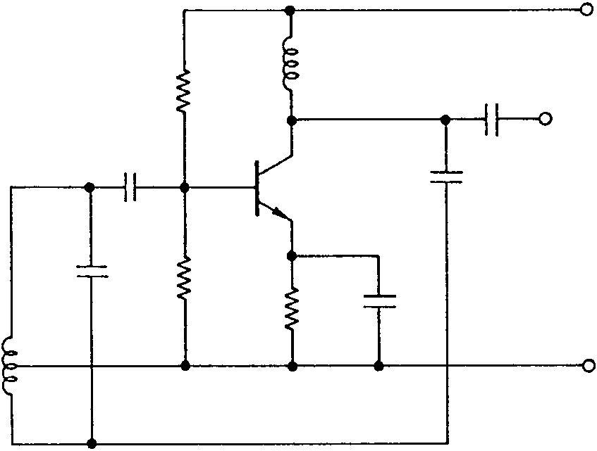
Most radio frequency oscillators – and some audio ones – use inductance and capacitance (LC) tuned circuits as the frequency determining elements. Figure 6.1 shows two commonly used basic circuits, the Hartley and the Colpitts.
The frequency is determined by the values of L and C1 (the combined values of C1 in the Colpitts circuit) and the amount of feedback by the collector choke and C2. Such circuits produce a very pure output but, principally because the physical dimensions of the frequency
85+ Ecc
 Output
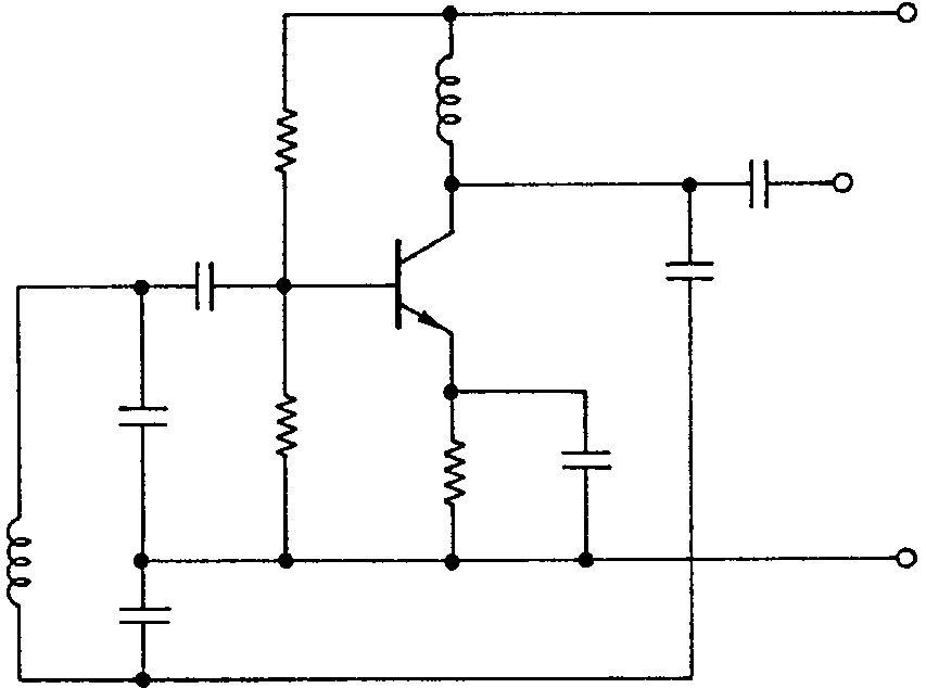 C2 (feedback)
determining components change with temperature, the accuracy of the set frequency is doubtful and is not very stable. Temperature compensation can be applied by selecting a capacitor for C1 with the correct negative temperature coefficient (assuming that the inductance increases with temperature), inserting temperature compensation for the rise in collector current with temperature and stabilizing the supply voltage. In the design of equipment an oscillator should be built into an area of low temperature change.