The problems of frequency accuracy and stability are largely overcome by using a quartz crystal as the frequency determining element (see Chapter 7).
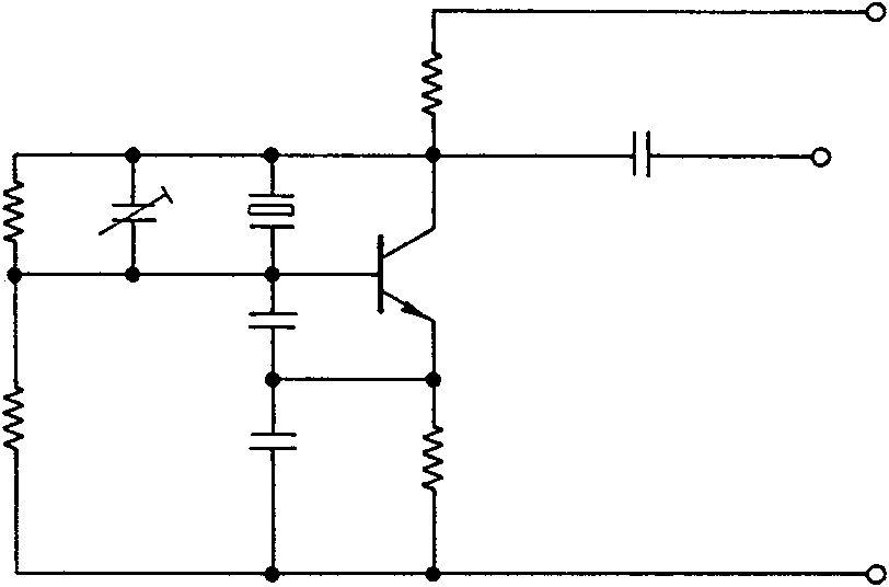
Figure 6.2(a) shows a circuit for an oscillator using the crystal’s parallel resonant mode. In this circuit, the rising voltage developed across Re on switch-on is applied via C1 to the base accelerating the rise of current through the transistor. When saturation is reached the voltage across Re becomes static and the voltage on the base falls, reducing the transistor current. The oscillations are only sustained
+ Ecc
 Output
+ Ecc
 Output
at the parallel resonant frequency of the crystal where it presents a high impedance between base and collector. Ct enables the parallel resonance of the crystal to be adjusted to a precise frequency.
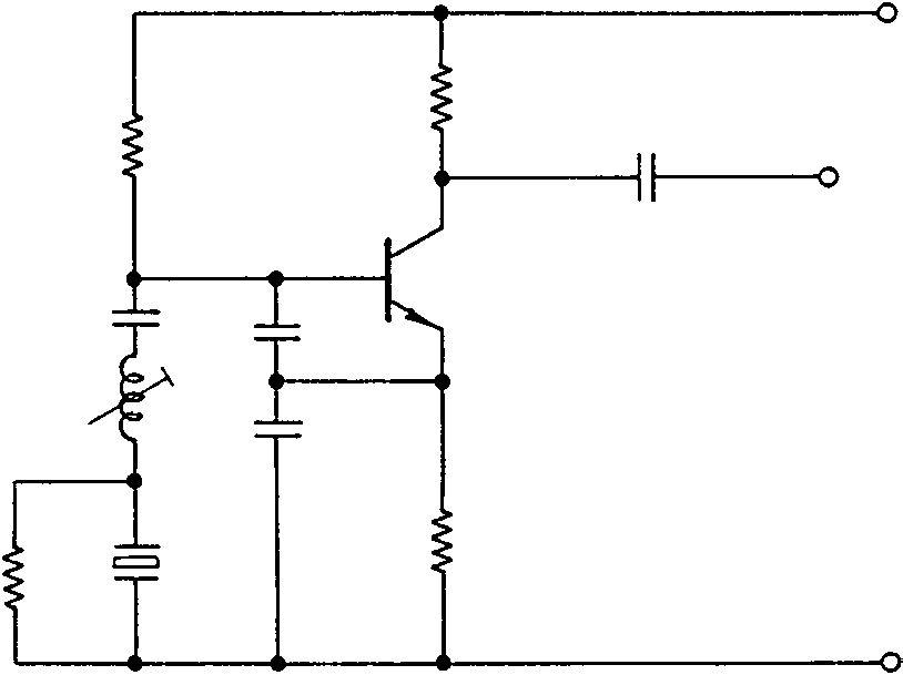
Figure 6.2(b) shows a series resonant crystal oscillator and here Lt is the tuning inductor of a Colpitts oscillator. The loop gain is adjusted so that the circuit will oscillate only at the series resonant frequency of the crystal where it presents a very low resistance. At other frequencies the crystal presents an increasing impedance in series with Lt, shunted by R which can be of a low value. When first setting the oscillator, Lt is adjusted, with the crystal short-circuited, for oscillation at a frequency close to that desired. The short-circuit is then removed and Lt used as a fine trimmer.
The same circuit will operate at the parallel resonant frequency of the crystal by making C1 equal to the crystal load capacitance.
The maximum frequency error permitted by the British Radiocommunications Agency specification MPT 1326 for mobile radio equipment designed for 12.5 kHz channel separation in the band 100–300 MHz is plus or minus 1.5 MHz. This is an overall accuracy of 0.0005% over the temperature range−10æCto+55æC. Well-designed standard crystal oscillators meet this specification, but higher stability can be obtained by operating the crystal in an oven at a constant higher temperature.
Until recently equipment which was required to change operating frequency quickly was fitted with several crystals, one for each operating frequency, and a change of frequency was made by selecting the appropriate crystal. Frequency synthesizer circuits are now normally used for such applications.
Piezoelectric crystals can oscillate at more than one frequency. The oscillations of a crystal slab are in the form of bulk acoustic waves (BAWs), and can occur at any frequency that produces an odd half-wavelength of the crystal’s physical dimensions (e.g. 1λ/2,3λ/2,5λ/2,7λ/2,9λ/2, where the fundamental mode is 1λ/2). Note that these frequencies are not exact harmonics of the fundamental mode, but are actually valid oscillation modes for the crystal slab. The frequencies fall close to, but not directly on, some of the harmonics of the fundamental (which probably accounts for the confusion). The overtone frequency will be marked on the crystal, rather than the fundamental (it is rare to find fundamental mode crystals above 20 MHz or so, because their thinness makes them more likely to fracture at low values of power dissipation).
The problem to solve in an overtone oscillator is encouraging oscillation on the correct overtone, while squelching oscillations at the fundamental and undesired overtones. Crystal manufacturers can help with correct methods, but there is still a responsibility on the part of the oscillator designer. It is generally the case that overtone oscillators will contain at least one L–C tuned circuit in the crystal network to force oscillations at the right frequency.