Frequency synthesizers offer the stability of a quartz crystal oscillator combined with the facility to change operating frequency rapidly. They are essential for equipment operating on trunked or cellular networks where the frequency of the mobiles is changed very rapidly on instructions from the network.
The advent of the variable capacitance diode (varicap), where the capacitance across the diode varies according to the applied DC voltage, made the frequency synthesizer a practicality.
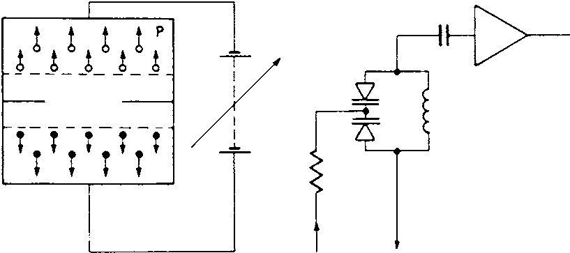
When a varicap diode replaces the tuning capacitor in an oscillator the circuit becomes a DC-voltage-controlled oscillator (VCO). The two varicaps in Figure 6.3 are used to minimize harmonic production and to obtain a greater capacitance change per volt.
P−
 CL
CLThe VCO is the circuit that directly generates the output frequency of a frequency synthesizer but, by itself, inherits the problem of frequency stability. To overcome this, the frequency and phase of the VCO are compared with those of a crystal-controlled high stability oscillator. Any frequency or phase difference between the two oscillators creates a DC voltage of the correct sense to change the frequency of the VCO to agree with that of the crystal oscillator.
While the stability of the crystal oscillator is transferred to the synthesizer output, additional noise is produced close to the operational frequency and the elimination of microphony requires careful physical design.
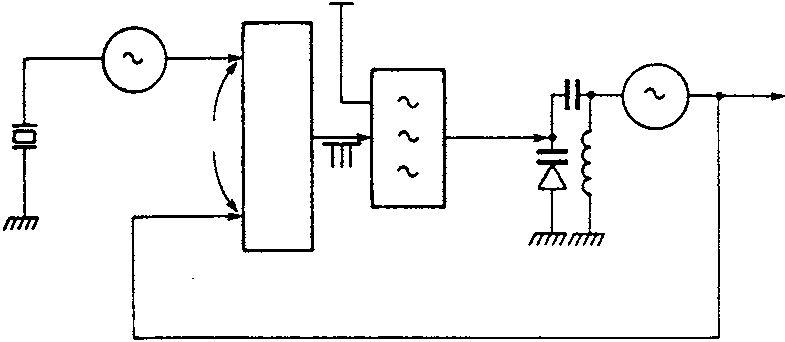
Figure 6.4(a) and (b) are diagrams of a simple phase-locked loop (PLL). The outputs of both the crystal oscillator and the voltagecontrolled oscillator are fed to the phase comparator which produces pulses whenever there is a frequency or phase difference between the two inputs. The pulses will be either positive or negative depending on the sense of the difference, and their width is dependent upon the magnitude of the differences. The pulses are then fed to a low pass loop filter which smooths them. If the time constant of the filter is sufficiently long it will completely remove the pulses and produce a DC output proportionate to the input pulse width which is applied to the VCO in the right sense to correct the frequency error. To enable the pulses to swing the VCO frequency in either direction, a small bias voltage of about 4 volts is applied to the varicap.
Identical frequencies have been selected for both oscillators in Figure 6.4 but in practice this is seldom the case. More frequently, theCrystal oscillatorDC offset Filter
 Phase comparator
 Phase comparator
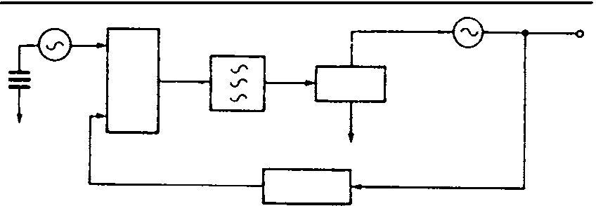
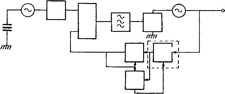
VCO runs at a higher frequency than the crystal oscillator and a divider is used to equate the frequencies applied to the phase comparator (Figure 6.5). Changing the division ratio provides a convenient means of tuning the oscillator.
100 MHz1 O/P 100 kHzø Varicapcomp
f
 ÷ 1000
 ÷ 999
÷ 999While the division ratio is 1000, the VCO will run at 100 MHz but if the division ratio is changed to 999 the comparator will produce pulses which, when converted to a DC voltage by the loop filter, will change the frequency of the VCO to 99.9 MHz, and the loop will lock at this new frequency.
The design of the loop filter is critical. Too long a time constant lengthens the settling time when changing frequency, yet if it is too short any deliberate frequency modulation will be removed. In practice, a relatively long time constant is chosen which is shortened by a ‘speed up’ circuit introduced whenever a channel change is called for.
The above values would enable a radio operating on a system with a channel separation of 100 kHz to change channel, but mobile radio channel separations are 25 kHz, 12.5 kHz or even 6.25 kHz at frequencies from 50 MHz to at least 900 MHz. To change channel at these frequencies a synthesizer must use a high division ratio. With a reference frequency applied to the comparator of 6.25 kHz and an operating frequency of, say, 450 MHz, the frequency select divider must have a ratio of 72 000, and be programmable in steps of 1 with a minimum operating speed of at least 900 MHz. A problem is then that the technology capable of meeting these requirements, emitter coupled logic (ECL), is power hungry, and the preferred LSI low power technology, CMOS, has a maximum operating speed of about 30 MHz. A simple ECL pre-scaler to bring the VCO frequency to about 30 MHz needs a ratio of 20 (500 MHz to 25 MHz). However, every change of 1 in the CMOS divider ratio then changes the total division ratio by 20. The solution is to use a dual modulus pre-scaler.
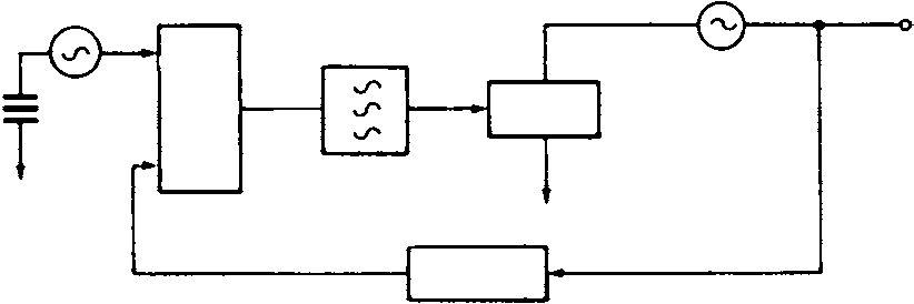
The division ratio of the dual modulus pre-scaler ( Figure 6.6)isprogrammable between two consecutive numbers, e.g. 50 and 51 (P and P + 1) and, in conjunction with two CMOS dividers, ÷Aand ÷N, provides a fully programmable divider.
Ref.
 ÷
÷The A and N dividers are pre-loaded counters. These count down and when the count value reaches zero they produce an output which changes the division ratio of the pre-scaler. The total division ratio, Nt, is decided by the initial programmed contents of the A and N counters and the setting of the pre-scaler. The initial content of the A counter must be less than that of the N counter.
Consider the pre-scaler set to divide by P + 1. For every count of P + 1, the contents of the A and N counters are reduced by 1 until the contents of the A counter are zero. The difference between the original contents of the A and N counters, N − A, remains in the N counter, and the total count, Nt,uptonow,is A(P + 1). At this point the division ratio of the pre-scaler is changed to P. Now, for every P count, the contents of the N counter are reduced by 1 until zero is reached. Under these conditions the total division ratio is given by:
Nt = A(P + 1)+ (N − A)P = AP + A+NP − AP =NP + A
For example, let P = 50 so P + 1 = 51, let N = 10 and A = 7. Then:
Now, change A to 6:
Nt = 10× 50+ 6 = 506 a change of Nt by 1.
VCO frequency = 455.6MHz Reference frequency = 12.5kHz
Calculate Nt, and the numbers which must be programmed into the A and N counters, assuming P = 50:
1. Calculate Nt = 455.6MHz/12.5kHz = 36 448.
2. Divide Nt by P: 36 488/50 = 728.96. Make N = 728.
3. For A, multiply fraction by P:0.96× 50 = 48.
4. Check Nt =NP + A = 728× 50+ 48 = 36 448.
Change A to 47: NP + A = 728× 50+ 47 = 36 447. 36 447×12.5kHz = 455.5875 MHz, the adjacent 12.5 kHz channel.
A method of direct digital frequency synthesis replaces the voltagecontrolled oscillator by a numerically controlled oscillator (NCO) where the function of the VCO is digitally synthesized.
The direct digital synthesizer generates an analogue sine wave from digital sine wave samples applied to a digital to analogue (D/A) converter. There are limitations to the method in terms of bandwidth and spectral purity.