When electrical stress is applied to one axis of a quartz crystal it exhibits the piezo-electric effect: a mechanical deflection occurs perpendicular to the electric field. Equally, a crystal will produce an e.m.f. across the electrical axis if mechanical stress is applied to the mechanical axis. If the stress is alternating – the movement of the diaphragm of a crystal microphone is an example – the e.m.f. produced will be alternating at the frequency of the movement. If the stress alternates at a frequency close to the mechanical resonance of the crystal as determined by its dimensions, then large amplitude vibrations result. Polycrystalline ceramics possess similar qualities.
Quartz crystals used for radio applications are slices cut from a large, artificially grown crystal. The slices are then ground to the appropriate size to vibrate at a desired frequency. The performance of an individual slice – the crystal as the end user knows it – depends upon the angle at which it was cut from the parent crystal.
Each crystal slice will resonate at several frequencies and if the frequency of the stimulus coincides with one of them the output, electrical or mechanical, will be very large.
The vibrations occur in both the longitudinal and shear modes, and at fundamental and harmonic frequencies determined by the crystal dimensions.
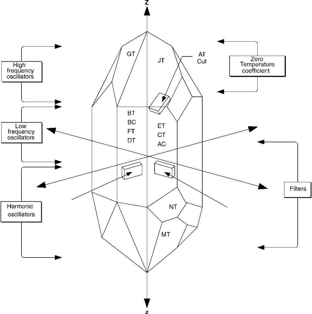
Figure 7.1A shows a typical natural quartz crystal. Actual crystals rarely have all of the planes and facets shown. There are three optical axes (X, Y and Z) in the crystal used to establish the geometry and locations of various cuts. The actual crystal segments used in RF circuits are sliced out of the main crystal. Some slices are taken along the optical axes, so are called Y-cut, X-cut and Z-cut slabs. Others are taken from various sections, and are given letter designations such as BT, BC, FT, AT and so forth.
95
Z
 Xcut
XcutZero
temperature coefficient
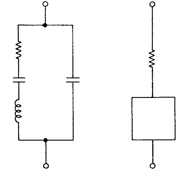 C0
C0and the mounting arrangements. C0, typically 3–15 pfd, represents the shunt capacitance of the electrodes in parallel with the can capacitance. If the oscillatory current is considered, the resonant frequency is decided by the values of C0 in series with C1, L1 and R1,and all crystals basically resonate in a series mode. Figure 7.2 illustrates the changes in impedance close to resonance. However when a high impedance, low capacitance, load is connected across the crystal terminals it behaves as a parallel tuned circuit exhibiting a high resistance at the resonant frequency. A crystal operating in the parallel mode oscillates at a higher frequency than that of series resonance.
+ jX
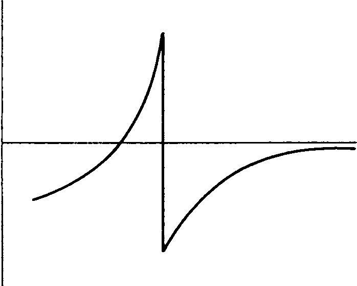 Frequency0
A crystal will resonate at its fundamental frequency or at one or more of its harmonics. As the desired resonant frequency is increased, a crystal slice operating at its fundamental frequency becomes extremely thin and fragile. Consequently, overtone crystals are composed of larger slices of quartz operating close to, but not necessarily at, an exact harmonic of the fundamental frequency. Crystals operating at the 3rd, 5th and 7th harmonics are often employed at frequencies above approximately 25 MHz.